


Introduction
Walking machines are devices being capable of walking locomotion by means of two or more legs [Reference Ceccarelli and Carbone1, Reference Ceccarelli and Keçeci2]. They are of special interest to researchers because of their better obstacle avoidance and stair climbing capabilities as compared with wheeled systems [Reference Ceccarelli and Carbone1, Reference Ceccarelli and Keçeci2]. Bipedal walking machines can be considered the most prominent type of walking machine in comparison with quadruped, hexapod, or any other legged robots. WABOT 1 is the world’s first biped walking machine developed at 1970s [Reference Kato3]. Leg architectures of biped walking machines are mostly based on serial kinematic chains, such as Asimo [Reference Chestnutt, Lau, Cheung, Kuffner, Hodgins and Kanade4], HRP-4C [Reference Kaneko, Kanehiro, Morisawa, Miura, Nakaoka and Kajita5], WABIAN-2R [Reference Kondo, Morishima, Ogura, Momoki, Shimizu, Lim and Takanishi6], BHR-5 [Reference Yu, Zhangguo, Ma, Chen, Zhang, Li and Gao7], and COMAN [Reference Rocchi, Hoffman, Farnioli and Tsagarakis8]. These biped humanoid robots have six degrees of freedom (DOFs) legs with 3-1-2 structure in terms of hip, knee, and ankle DOFs, respectively. Lola is another example with an extra passive toe joint (3-1-2+1) [Reference Richard, Gosselin and Kong9]. Similarly, there are prototypes adding more than 6-DOFs such as reported in ref. [Reference A.M., Orner, Kondo, Morishima, Carbone, Ceccarelli and Takanishi10].
There are few examples of leg architectures for walking machines based on parallel mechanisms. EP-WAR and Chebyshev-Pantograph leg are examples of planar parallel mechanisms with single DOFs legs [Reference Ceccarelli and Carbone1]. WL-16R comprises a spatial parallel mechanism leg architecture [Reference Sugahara, Endo, Lim and Takanishi11] with 6-DOFs Gough-Stewart platform type of legs. WL-16R can carry an adult human weighing up to 60 kg. LARMbot Locomotor is an example of reduced DOFs spatial parallel leg architecture with 3-DOFs 3-UPU leg architecture (U and P represent universal and prismatic joints, respectively) [Reference Wang and Ceccarelli12–Reference Ceccarelli, Russo and Morales-Cruz14].
Walking machines can operate in two different operation conditions, namely as static walking and dynamic walking. In static walking, projection of center of mass is ensured to be inside of the foot support area. Although the center of mass of the walking machine can be outside of the support area in dynamic walking mode, zero moment point cannot be outside [Reference Vukobratović and Stepanenko15, Reference Al-Shuka, Corves, Zhu and Vanderborght16]. As opposed to dynamic walking, static walking requires simpler control strategy but walking speeds are slower and walking machines are mostly suitable for flat ground surfaces.
Some existing bipedal walking machines are compared with leg architectures in Table I. Biped walking machines with 6-DOFs serial mechanisms provide a larger workspace than other types. However, their payload to weight ratio is relatively low compared to leg designs with parallel kinematic structures. Their larger workspace makes them suitable for dynamic walking. Their mechanical designs are complex because of their complex joint designs, such as the 3-DOFs hip joint. Operation of six actuators requires complex actuation and control systems, so their costs are relatively high. Planar parallel mechanisms are usually composed of 1-DOF legs with pantograph linkages. This type of walking machine has a simple mechanical design, a simple control architecture, and a low-cost design. However, they can only follow predesigned trajectories. Accordingly, they are only appropriate for static walking. Another drawback of this type of walking machines is low payload/weight ratio. Spatial parallel leg mechanisms with 6-DOFs legs are good in terms of payload/ to weight ratio. Their stability is better than planar parallel types, and they can be used for dynamic walking. Their workspace is limited due to the parallel kinematic architecture. Their mechanical design and control architecture is complex, and costs are high.
Table I A comparison of main characteristics of leg architectures based on refs. [Reference Kato3–Reference Sugahara, Endo, Lim and Takanishi11].

Human leg movement can be represented as a parallel mechanism due to the muscular system by considering the leg anatomy [Reference Ceccarelli and Carbone17, Reference Jamisola and Roberts18]. New hybrid structured parallel leg mechanisms with less than 6-DOFs legs are advised in ref. [Reference Ceccarelli and Carbone17] that are composed of rigid links and cables. By hybrid, it is intended combination of different design solutions such as combination of cables and rigid links. Cables are particularly useful since they provide a low-cost and lightweight design solution as outlined for example in ref. [Reference Hernández-Martínez, Ceccarelli, Carbone, López-Cajún and Jáuregui-Correa19]. Reduced DOFs parallel leg architectures can be designed to achieve simple solutions such as proposed in ref. [Reference Ceccarelli and Carbone17], that are suitable for flat surface applications. Roll and pitch orientation DOFs are needed for rough terrain adaptability and rotation of the robot can be altered by waist rotation. Hence, parallel leg architectures with three translational DOFs are sufficient for flat surface applications. In static walking, projection of the center of total mass of a biped robot should always remain inside the foot support area. A biped walking machine can guarantee the static equilibrium with three translational DOFs legs that can provide translations along the X–Y–Z Cartesian axes. Two translations provide the required motions in the sagittal plane to advance in the direction of the walking while the other translational DOF allows to keep the projection of center of mass within the foot support area. In this static walking, the feet remain always parallel to the ground. Proper mass distribution and foot contact surface geometry are crucial for allowing such a walking operation.
There are many translational parallel mechanisms (TPM) in the literature. The most famous TPM is Clavel’s Delta Robot [Reference Clavel20]. Delta robots are generally used for pick and place applications in the industry. Each leg of this robot has same kinematic chain RRPaR where R and Pa represent revolute joints and a parallelogram loop, respectively. Three parallelogram loops constrain rotations of the mobile platform and the Delta Robot possesses pure translational motion. Another type of Delta Robot is achieved by replacing rotary actuators on the fixed platform by linear actuators (called as linear Delta or Linapod) [Reference Zobel, Di Stefano and Raparelli21]. Linapods are used as an alternative of Cartesian Robots in 3D printing applications. A 3-UPU mechanism is designed by Joshi and Tsai [Reference Joshi and Tsai22] where U and P represent universal and prismatic joints, respectively. Each leg of the mechanism has 5-DOFs and restricts one rotational DOF of the mobile platform (independent from each other). Each prismatic joint is driven by a linear actuator. Note that a parallelogram loop or a UPU leg can be used to constrain a rotation of mobile platforms of new mechanisms. Three of them with independent constrained rotation axes are sufficient to have a TPM. Many other examples can be found in refs. [Reference Kong and Gosselin23–Reference Carricato and Parenti-Castelli26]. Such mechanisms with only rigid links have disadvantages in terms of the total weight of the mechanism.
The 3-DOFs parallel mechanisms with cables and rigid limbs can overcome limited workspace, complex mechanical design, and complex control system problems of spatial parallel mechanisms. This type of architecture can be advantageous in terms of inertia and cost when compared to serial and spatial parallel mechanisms with rigid links only. Different type of mechanisms can be developed to design such a system where the cables can be active or passive. The number of rigid links can be determined according to the desired stiffness performance.
There are few parallel mechanisms with cables and rigid limbs in the literature. Betabot is a TPM in which a passive rigid link, and three active cables are used [Reference Behzadipour, Khajepour and Cubero27]. Dishbot is another example where a set of passive cables are used in addition to three active cables and a passive rigid link [Reference Behzadipour, Khajepour and Cubero27]. Both designs use passive rigid links instead of a redundant cable. In ref. [Reference Arai, Yuasa, Mae, Inoue, Miyawaki and Koyachi28], a 6-DOFs parallel mechanism is designed inspired from a Stewart platform as an example of actuated rigid links and cables in combination. Four cables and three rigid links are used. Rigid links have SPS structure where S stands for a spherical joint and P stands for a prismatic joint.
In this paper, we innovate the above-mentioned existing design solutions by proposing the combination of rigid links with cables. To the authors’ knowledge, no similar kinematic design has been previously proposed. The number of feasible options for such design is quite limited. So far, we have identified only two feasible design alternatives. Both design alternatives have been presented in this paper. This work deals with design of a novel hybrid structured leg mechanism with capability of static walking. This paper proposes for the first time a hybrid cable-constrained parallel leg mechanism as a novel design solution for legged walking machines. A reduced DOFs leg architecture is preferred to achieve a low-cost easy-operating walking machine. A preliminary study with the first results for the design of proposed mechanism is presented in ref. [Reference Demirel, Carbone, Ceccarelli and Kiper29]. The proposed (UU-2Pa)-P mechanism is one of the few cable-constrained parallel manipulator designs in the literature. Unlike cable-driven mechanisms, here only rigid links are actuated while cables are fully passive, so that no redundant actuation is required. The advantage of using passive cables becomes more important in terms of lightweight design when increasing the thigh length. The mechanism is designed specifically as a leg mechanism for walking machines. The most significant contribution to the prototype costs is given by the actuator and control system. Using reduced DOFs solutions such as 3-DOFs leg architecture allows to reduce the actuator and control system costs while keeping a suitable performance for walking on flat surfaces. The proposed design solution could be extended to other applications such as robotic arms for pick and place tasks.
This paper is arranged as follows. In Section 2, design features and description of the novel hybrid leg mechanism are given together with a kinematic analysis. In Section 3, a prototype is presented, and experimental validation is carried out for investigating the operational performance of the leg mechanism for planar motion in sagittal plane. Experimental results are discussed for a prescribed motion to achieve a desired walking gait. Finally, Section 4 summarizes the paper’s contribution.
2. Design of the Leg Mechanism
As first design step, we define here the main design requirements and constraints. Namely, we aim at a design solution with a reduced number of DOFs to reduce complexity and costs. For the purpose, a topology search led use to identify a 3-DOFs hybrid structured parallel manipulator with pure translational motion as sufficient for our intended application to operate in a static walking mode in flat surface applications. This type of a leg design can achieve fundamental walking functions such as straight walking, side walking, and crossing over obstacles. Cables in such a mechanism can be used as active or passive, that is, a cable-driven or a cable-constrained system can be designed. Cable-driven mechanisms require redundant cable(s) to ensure that the cables are in tension at any time. Use of redundant cable(s) results in actuation redundancy which is not preferred in this investigation for a low-cost and easy-operating design. According to above-mentioned design, criteria for the leg mechanism can be listed as:
-
Structure: hybrid cable-constrained parallel mechanism
-
DOF of each leg: 3-DOFs with pure translational motion
-
Walking mode: static walking
-
Operation environment: flat surface
-
Walking functions: straight walking, side walking, and crossing over obstacles
-
Application field: humanoid biped robots and service robots
Given the above-mentioned requirements, we have developed the conceptual design of two feasible cable-constrained 3-DOFs TPMs.
2.1. Conceptual design I
The kinematic structure and a CAD model of the first conceptual design are given in Fig. 1. The kinematic structure is (UPU-2Pa)-(UPU-2Pa) where U stands for universal joint, P stands for prismatic joint, 2Pa stands for two parallel loops are serially attached to each other. Underlined joints are actuated, and Pa represents a parallelogram loop. This mechanism consists of a hip platform, a middle platform (knee), and a moving platform (foot), four rigid links and two parallelograms. The motion of the middle and moving platforms is analyzed with respect to the hip platform. Two rigid links form a P-joint (P1) which connect the hip to the knee by two U-joints (UH and UK) at each end. Likewise, P2 connects the knee to the foot by two U-joints (UK and UF). Two P-joints (P1 and P2) have reciprocating motion which means they can be actuated by a single actuator. P-joints (P1 and P2) provide translation along z direction. Rotation axes of U-joints (UH, UK, and UF) are perpendicular and coincident. They provide rotation about x and y directions. UH is actuated by two rotary actuators. Parallelograms (Pa) are composed of passive cables and twelve pulleys (PH1–4, PK1–4, and PF1–4). Each pulley is connected to the related platforms by a passive revolute joint (R-joint). Two gimbals are designed for UH and UK. Also, two ball screws are used to provide reciprocating motion where the first ball screw has a hallow shaft. UHP1UK leg constrains rotation of the knee platform with respect to the hip platform about the z-axis. Similarly, UKP2UF constrains rotation of the foot platform with respect to the knee platform. Two parallelograms with the blue R-joints constrain rotation of the knee and foot platforms about the x-axis. Correspondingly, the two parallelograms with the green R-joints constrain rotation of the platforms about the y-axis. Since three orientation DOFs are constrained, the knee and foot of the mechanism have pure translational motion.

Fig. 1. The first conceptual design: (a) the kinematic structure and (b) the CAD model.
Details of the U-joints are shown in Fig. 2. The actuated gimbal design consists of two rotary parts (GimbalH1 and GimbalH2) which are connected to the rest of the mechanism with a rigid link (Fig. 2a). GimbalH1 rotates the link about the x direction where GimbalH2 rotates it about the y direction. Rigid link-GimbalH2 contact has considerable amount of friction. Although friction is a drawback of this design and several types of actuated gimbal mechanisms exist, we propose a specific gimbal design with two rotary actuators having independent motion so that each motor does not carry the weight of the other one. A closer view of GimbalK is shown in Fig. 2b. GimbalK connects the second nut to the knee and allows rotation about x and y directions. The pulleys (Fig. 2c) have same amount of rotation about the same directions as GimbalH and GimbalK: PH1–2, PK1–2, PF1–2 rotate with the same amount of rotation of GimbalH1 whereas PH3–4, PK3–4, and PF3–4 rotate with the same amount of rotation of GimbalH2.

Fig. 2. Details of the conceptual design: (a) GimbalH, (b) GimbalK, (c) pulley.
2.2. Conceptual design II
The kinematic structure of the second conceptual design is (UU-2Pa)-P as shown in Fig. 3a. This mechanism consists of same three platforms as a hip platform, a middle platform (knee), and a moving platform (foot). A rigid link (thigh) is connected to the hip and the knee by two U-joints (UH and UK). UH is actuated by two rotary actuators. Two rigid links (shank) form an actuated P-joint (P1) and connect the knee to the foot. UH and UK rotate about axes along x and y directions. P1 allows to translate the foot with respect to the knee along z direction. Four equal long passive cables connect the hip to the knee and are anchored at points (AH1–4 and AK1–4). Two parallelogram loops are composed of four passive cables, the hip, and the knee. Actually, three cables are enough to form two parallelograms (one mutual cable in parallelograms). However, Fig. 3 proposes a solution with four cables. This solution includes one redundant cable. This allows to obtain a symmetrical design with two independent parallelogram loops. As long as the cables are in tension, they can be considered to be equivalent to a rigid link with a S-joint at each end. Rotation of the knee with respect to the hip about z direction is constrained by the UHUK leg. The parallelogram loops constrain the rotation of the knee with respect to hip about x and y directions. The hip and knee platforms that are connected with cables and the rod constitute a Wren platform [Reference Wren30] with SS, and/or US and/or UU legs [Reference Kiper and Söylemez31]. The motion of a Wren platform comprises a 2-DOFs pure translational mode thanks to the n − 1 independent parallelogram loops that are constructed by the n legs (cables and the rod in our case).

Fig. 3. The second conceptual design: (a) the kinematic structure and (b) the CAD model.
Therefore, proposed mechanism has knee and foot platforms with pure translational motion. The same GimbalH design is used in both designs.
A 3D CAD design of the proposed mechanism is developed in Solidworks® environment (Fig. 3b). Cables are modeled as rigid links with S-joints at each end. Four sets of cable pairs are used to form parallelogram loops, and they keep the platform parallel to each other. Since the mass of the cables and cable connection parts are very low when compared with the other components, using redundant cables results in negligible amount extra mass. Actuated U-joint (UH) is constructed with a gimbal design (GimbalH) that is indicated with the orange links in Fig. 3b. Two rotary actuators indicated with black boxes actuate the GimbalH. GimbalH rotates about y direction with considerable amount of friction. A commercial U-joint product is used as a passive universal joint (UK) and the shank is modeled as a linear actuator.
Independent motions of the leg mechanism in four different positions are illustrated as snapshots in Fig. 4 with θ H1 (about x direction), θ H2 (about y direction), and s (along z direction) that are actuated joint variables. Home position of the leg mechanism is shown as solid model where all joint variables are equal to zero. Red, blue, and black models show motions for θ H1 = 30°, θ H2 = –30°, and s = 50 mm, respectively.

Fig. 4. Snapshots of independent motions of the leg mechanism with corresponding actuation inputs: (a) θ H1 = 30°, (b) θ H2 = –30°, (c) s = 50 mm.
Comparing the two conceptual designs, the second design is less complicated. Since the thigh and the shank are collinear for the first design, the second design is a more human-like design. Two ball screws solution for reciprocating motion, an extra gimbal design for the UK, and more complicated passive cable connection details make the first design less favorable. The second solution is selected to proceed with a detailed kinematic analysis as follows.
The proposed leg mechanism can be simplified as a UP kinematic chain, that is, a 2-DOFs inverted pendulum, which can rotate about x and y directions, connected to an extendable link which moves in z direction. This simplification can be made since the leg mechanism possesses pure translational motion. Accordingly, UK joints and cable connection angles have no effect on computing the position of the foot with respect to the hip. Fig. 5 depicts a simplified model with link and joint parameters. Length of the thigh link is defined as l T . Hip joints UH1 (orange) rotates about x direction, whereas UH2 (blue) rotates about y direction. Shank joint P1 translates along z direction. The thigh link rotates about hip point (OH) by an amount of θ H1 about x direction and θ H2 about y direction. The knee point OK is at PK(0, 0, l T ) with respect to fixed reference frame OH(x, y, z) when θ H1 = θ H2 = 0. Foot point OF is translated from OK by an amount of s along z direction. Shank length |OKOF| = s can be defined as s = l s + Δs by considering the minimum length of the shank (l s ). Direct kinematics formulation can be derived to compute position of OF(O Fx , O Fy , O Fz ) in OH(x, y, z) frame depending on actuated joint angles θ H1, θ H2 and displacement s in the form
 \begin{equation}\left[\begin{array}{c} O_{Fx}\\ \\[-9pt]
O_{Fy}\\ \\[-9pt]
O_{Fz} \end{array}\right]=\left[\begin{array}{c@{\quad}c@{\quad}c} 1 & 0 & 0\\ \\[-9pt]
0 & \cos \theta _{H1} & \sin \theta _{H1}\\ \\[-9pt]
0 & -\sin \theta _{H1} & \cos \theta _{H1} \end{array}\right]\left[\begin{array}{c@{\quad}c@{\quad}c} \cos \theta _{H2} & 0 & -\sin \theta _{H2}\\ \\[-9pt]
0 & 1 & 0\\ \\[-9pt]
\sin \theta _{H2} & 0 & \cos \theta _{H2} \end{array}\right]\left[\begin{array}{c} 0\\ \\[-9pt]
0\\ \\[-9pt]
l_{T} \end{array}\right]+\left[\begin{array}{c} 0\\ \\[-9pt]
0\\ \\[-9pt]
s \end{array}\right]\end{equation}
\begin{equation}\left[\begin{array}{c} O_{Fx}\\ \\[-9pt]
O_{Fy}\\ \\[-9pt]
O_{Fz} \end{array}\right]=\left[\begin{array}{c@{\quad}c@{\quad}c} 1 & 0 & 0\\ \\[-9pt]
0 & \cos \theta _{H1} & \sin \theta _{H1}\\ \\[-9pt]
0 & -\sin \theta _{H1} & \cos \theta _{H1} \end{array}\right]\left[\begin{array}{c@{\quad}c@{\quad}c} \cos \theta _{H2} & 0 & -\sin \theta _{H2}\\ \\[-9pt]
0 & 1 & 0\\ \\[-9pt]
\sin \theta _{H2} & 0 & \cos \theta _{H2} \end{array}\right]\left[\begin{array}{c} 0\\ \\[-9pt]
0\\ \\[-9pt]
l_{T} \end{array}\right]+\left[\begin{array}{c} 0\\ \\[-9pt]
0\\ \\[-9pt]
s \end{array}\right]\end{equation}

Fig. 5. Simplified kinematic model with link and joint parameters.
Velocity and acceleration level kinematics can be computed by taking derivatives
 \begin{equation}O_{Fx}=-l_{T}\sin \theta _{H2}, O_{Fy}=l_{T}\sin \theta _{H1}\cos \theta _{H2},O_{Fz}=l_{T} \cos \theta _{H1}\cos \theta _{H2}+s\end{equation}
θ H1, θ H2, and s values can be found using inverse kinematics for given position of the foot point OF as
 \begin{equation}\theta _{H2}=\sin ^{-1} \frac{-O_{Fx}}{l_{T}}, \theta _{H1}=\sin ^{-1} \frac{O_{Fy}}{l_{T}\cos \theta _{H2}}, s=O_{Fz}-l_{T} \cos \theta _{H1}\cos \theta _{H2}\end{equation}
A preliminary dynamic simulation is performed to check actuation torques, actuation force, and reaction forces by using SolidWorks® Motion Analysis toolbox and presented detailly in ref. [Reference Demirel, Carbone, Ceccarelli and Kiper29]. A prototype of the proposed leg mechanism is designed.
3. Prototype Design and Experimental Validation
3.1. Prototype design
The CAD model of the leg mechanism is shown in Fig. 6a. Platforms are composed of aluminum profiles. The components of the gimbal design presented in Section 2 are produced with polyoxymethylene material. Two sets of cables on two opposite sides of the platforms are used to construct the four parallelogram loops. Cable connectors are designed to guide cables with holes and pulleys (V-groove bearings). Laser cut acrylic plates are used to guide the cables and precise connection of the components attached to the hip and the knee. Since linear actuators generally cannot operate in relatively high speeds, a slider-crank linkage is used to achieve translational motion of the knee joint. In ref. [Reference Demirel, Carbone, Ceccarelli and Kiper29], there are two parallel cables as line segments on each side (totally eight cables), whereas in the new prototype there are four cables in total. The use of four cables ensures that at least two cables are always in tension. In fact, cables can only pull and not push. Accordingly, at least one redundant cable is required to ensure that if a cable at one corner is slack, the cable at the opposite corner keeps pulling. The cable redundancy guarantees the presence of at least one parallelogram loop with tensioned cables in any operation condition. This parallelogram loop – together with the rigid rod at the middle, hip, and knee – guarantees that the platforms remain parallel to each other at all times. It is worth noting that a proper operation of this redundant set-up requires that all four cables have exactly the same length of the thigh link. Therefore, the cable lengths should be carefully calibrated and tightened.

Fig. 6. Design and dimension parameters of the leg mechanism: (a) the CAD model and (b) design parameters.
Fishing lines that can carry up to 45 N are used in the prototype. A parallelogram loop composed of two cables can carry up a load up to 90 N. The translational motion between the knee and the foot was originally planned via a linear actuator, whereas this is here done via a slider-crank mechanism.
Main specifications of the prototype are listed in Table II. The 3-DOFs leg mechanism is designed for 200 mm × 50 mm step length (SL × SH). Stepper motors are used for the actuation. Total mass of the prototype (mL) is 10.84 kg (6.7 kg due to actuators). Dimension parameters of the leg mechanism are listed in Table III by referring to the design parameters in Fig. 6b. Dimensions are determined according to desired step size. The thigh length (l T ) is determined for ± 30° rotation of θ H1. Δs max is found as 80 mm for this step size. The crank (l C ) and coupler (l CO ) lengths are designed according to Δs max, and a proper l C /l CO ratio is selected. The crank length is selected to be longer than half of Δs max, because the crank cannot have 180° rotation range due to collusion with the knee platform. Passive cable system mass is about 121 g including masses of cables, guiding components, and turnbuckles. If two rigid links with U-joints at end were used instead of the four cables, there would be considerable extra weight. If the smallest available commercial U-joint in the market (DIN 808 U-joint, 50 g mass) and 6 mm steel rods (4000 series, 44 g mass) are used, the total mass would be 288 g, which is more than twice the mass of the proposed cable system. Of course, a higher number of rods with larger rod diameters could be required to carry a heavy upper structure while guaranteeing the required stiffness. Further details on the modeling and analysis of stiffness for biped walking can be found, for example, in refs. [Reference Ceccarelli and Carbone32, Reference Carbone, Lim, Takanishi and Ceccarelli33].


The built prototype is presented in Fig. 7. 3D-printed components are used as connection parts. Other components are selected from available products in the market. Two stepper motors (Oriental Motor Pk E 4.5A) actuate the gimbal, whereas another stepper motor (Shinano SST59D-5150) actuates the slider-crank linkage. Two magnetic encoders (Ams AS5048B) are attached to the output shaft of the actuated hip joint (θ H1) and the crank of the slider-crank linkage. The slider-crank mechanism is used to obtain linear motion between the knee and the foot platforms. Actuator inputs are designed by using a degree 5 polynomial to get a smooth motion of the foot. A real-time PCI controller is used to apply velocity profile control and to collect data from magnetic encoders. The prototype costed about 1000 €, namely 585 € are for the stepper motors and drivers, 50 € are for the encoders, 15 € are for the 3D-printed components, 350 € are for the off-the-shelf components such as the sigma profiles, steel rods, cars for the linear guides, bearings, cardan joints, fasteners, shaft couplings, turnbuckles, and other elements for rigid connections.
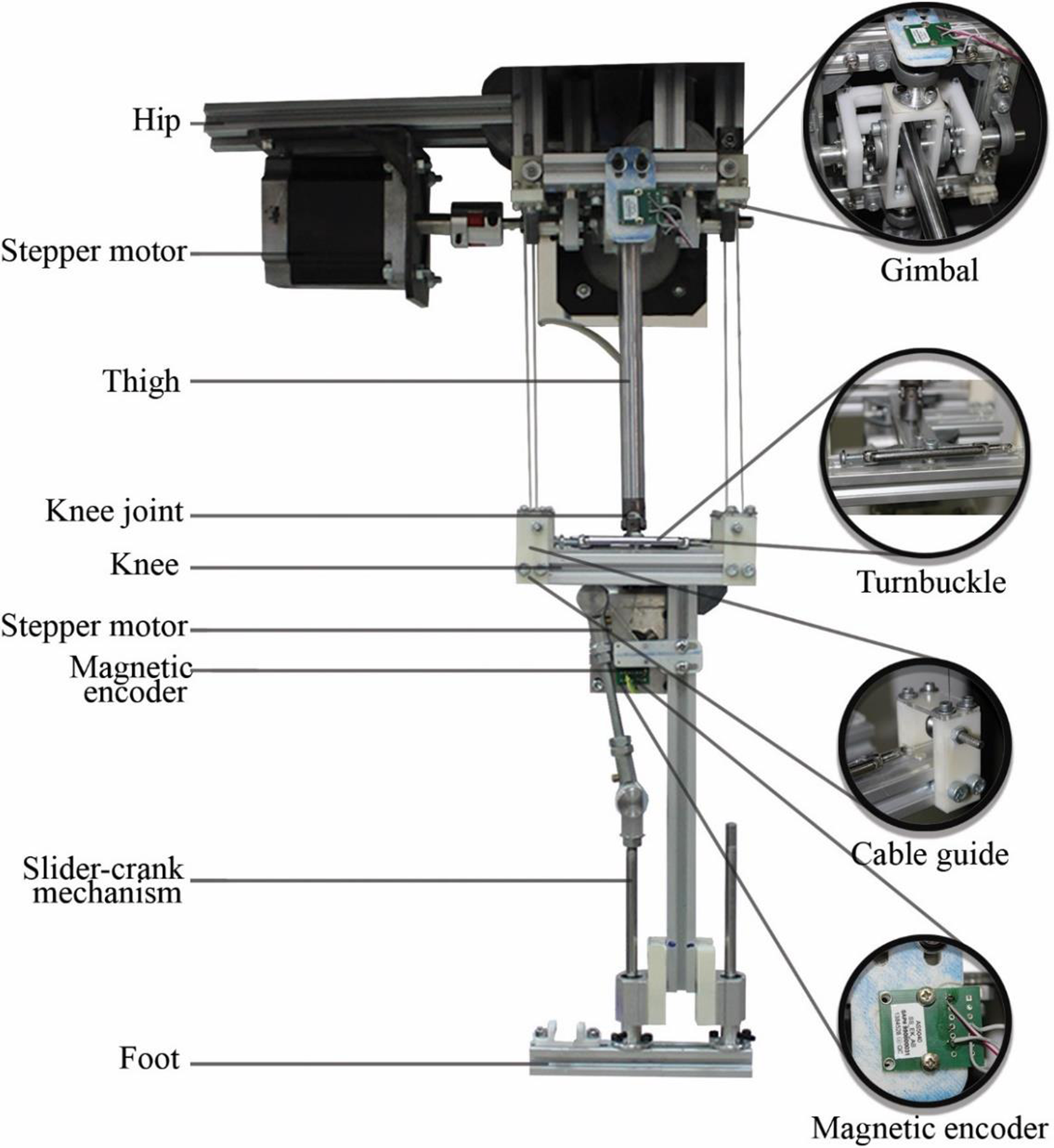
Fig. 7. The built prototype of the leg mechanism for validation tests.
Turnbuckles are used to calibrate the tension of the cables. A calibration process is performed with the help of a water gauge to make all cables in same length and tension. The calibration process is repeated to ensure that the cables do not get loose during the motion and also verify that the knee platform remains parallel to the hip platform at several configurations of the mechanism.
3.2. Experimental validation
The proposed experimental set-up of the leg mechanism is shown in Fig. 8. It consists of a single leg that is tested for off-ground walking tests on the sagittal plane. Side motion tests cannot be conducted with the proposed experimental set-up, since side motion planning requires the coordination of both legs. Accordingly, the proposed side by side tests are not feasible with the proposed experimental set-up, and they might only be considered for future studies after developing a new experimental set-up with two legs. A real-time PCI card (Humosoft MF 624) is used as a controller. Stepper motors are actuated by two types of stepper drivers (DQ258M and DM278M). The black fixed frame is used for fixing the hip platform and the stepper motors of the gimbal. The target trajectory is fixed on the frame, and a laser pointer attached to the foot is used to visualize the foot trajectory. Open loop velocity profile controller is modeled in Matlab/Simulink® environment.

Fig. 8. Experimental set-up of the leg mechanism prototype in Fig. 7.
Trajectory of the foot point is adjoining of half of an ellipse, and a straight line (Fig. 9a). 200 mm × 50 mm (SL × SH) walking gait is planned for 8 s step time. The half ellipse and straight-line segments correspond to swinging and stance phases, respectively. The foot point tracks A-B-C-A sequence with 2 s time in the AB and CA segments and 4 s in the BC segment. 8 s step time is slow for a leg mechanism, but the prototype focuses on capability of the mechanism to accomplish desired walking gait. Low project budget and applied open loop control system are also reasons for the slow motion. The actuator inputs for the walking gait in sagittal plane are planned by using a degree 5 spline. In addition to the inverse kinematics equations found in Section 2, the crank angle θ S should be computed for the desired s as

Fig. 9. The planned walking gait for the validation tests: (a) trajectory of the foot point in sagittal plane (YZ-plane) and (b) velocity profiles of the motors.
 \begin{equation}\theta _{S}=\cos ^{-1} \frac{{l_{C}}^{2}+s^{2}-{l_{CO}}^{2}}{2l_{C}s}\end{equation}
The initial position of the leg mechanism is point A. The motion of the actuated joints (θ H1 and θ S ) is computed in three segments as AB (0–2 s), BC (2–6 s), and CA (6–8 s). The mechanism stops at points A, B, and C; therefore, velocity and acceleration values are zero at these points. Velocity profiles of the motors for a single step are shown in Fig. 9b. The other actuated hip joint remains stationary (θ H2 = 0) during the motion. Motion of this joint is required for side walking and diagonal motions. Although presented mechanism is designed to achieve biped walking, this is kept out of the scope of this paper.
The leg mechanism prototype is operated for the desired walking gait to test the trajectory tracing performance. Trajectory of the experiment is traced three times (three steps). PCI controller is run at 10 kHz, and the input data are generated accordingly. Angular displacement data of the actuated shafts are collected using rotary magnet encoders. Proportional gains are added to the input velocity profiles with respect first measurement, and positioning errors are decreased. Experiment is repeated three times. Snapshots of the first step are shown in Fig. 10. A prototype video taken during the tests is provided as a supplementary material.

Fig. 10. Snapshots of a validation test using the test set-up in Fig. 9.
The desired and measured positions of the actuated joints angles (θ H1, θ S , θ H1mes, θ Smes) for three steps of walking are shown in Fig. 11. The desired joint angles are calculated by using the inverse kinematics equations (3) and (4). Maximum errors between the desired and measured angles for the hip joint are Δθ H1M1 = 0.93°, Δθ H1M2 = 1.28°, and Δθ H1M3 = 1.29° for measurements 1–3, respectively. Maximum errors of the slider-crank linkage are Δθ SM1 = 1.4°, Δθ SM2 = 0.86°, and Δθ SM3 = 0.82°. Repeatability of the motion is good.

Fig. 11. Desired and measured angular displacements of the actuated, (a) hip joint (θ H1) and (b) slider-crank linkage (θS).
Desired and computed positions are shown in Fig. 12. Sagittal plane motions of the foot are shown in Fig. 12(a). Fig. 12(b) shows y- and z-axis errors (mean of all experiments) based on encoder data. The maximum positioning error is 9.65 mm in y direction and 3.81 mm in z direction. The mechanism can accomplish BC and CA segments successfully but there are relatively large errors during the AB segment. Vibrations have considerable effect on positioning errors. Since positioning errors are computed by using kinematic equations and collected sensor data are taken from magnetic encoders, the computed errors seem to be higher than errors seen in Fig. 10 and the video (supplementary material). The computed errors including manufacturing and assembling errors can produce significant difference between designed and real kinematic parameters.

Fig. 12. Desired and computed positions of the foot point according to encoder data, (a) sagittal plane, (b) y-axis (horizontal), and z-axis (vertical) errors.
The obtained results demonstrate the engineering feasibility of the proposed design as a suitable solution for achieving static walking with only three motors per leg instead of the six motors commonly required for a legged locomotion. This allows a reduction of the robot’s own weight as well as a strong reduction of the complexity for the control of the locomotion.
It is to note that the low available budget has limited the manufacturing quality resulting in limited accuracy in path following tasks. Improving the manufacturing and using a close loop control in combination with proper sensors and servomotors will be planned as future work once a full biped prototype can be made available. Similarly, biped walking tests for straight walking, side walking, and crossing over obstacles are planned as future studies.
4. Conclusions
In this paper, two novel 3-DOFs cable-constrained parallel leg mechanisms are proposed as a design solution for a lightweight, low-cost walking machine to be used on flat surfaces. The proposed design solutions are based on (UPU-2Pa)-(UPU-2Pa) and (UU-2Pa)-P kinematic architectures. The (UU-2Pa)-P mechanism is proposed with fairly simple kinematic equations to perform a desired walking gait in static walking operation conditions. The first proposed single leg prototype has a simple mechanical structure with anchored cables and a convenient kinematics for walking operation. The second proposed single leg prototype has an improved and more complex mechanical structure including a novel actuated gimbal design on the hip platform as a suitable solution for moving the shank. Also, it includes a cable tensioning solution with turnbuckles for improving the cable-constrained mechanisms. Tests of the prototypes show proper results in accordance with the design requirements for achieving static walking with only three motors per leg instead of the six motors commonly required for the legged locomotion. This proves the engineering feasibility of the proposed parallel leg mechanism designs that can allow a reduction of the leg’s own weight and a reduction of the control complexity when used for a biped locomotion in static walking tasks.
Supplementary material
To view supplementary material for this article, please visit https://doi.org/10.1017/S0263574723000140.
Acknowledgments
Part of this work was developed during an Erasmus visit of the first author at LARM: Laboratory of Robotics and Mechatronics, University of Cassino, Italy under the supervision of Prof. Ceccarelli and Prof. Carbone. We would like to thank Dr. Emre Uzunoğlu and Dr. Danielle Cafolla for helping with the design and prototype activities.
Author Contributions
MC proposed the idea of a lightweight hybrid robotic leg structure with rigid links and cables. MD and GK constructed the kinematic structure. MD performed the design, prototype production, and tests, GK, GC, and MC supervised the design, manufacturing, and testing. MD wrote the first draft, GK, GC, and MC provided draft revision and supervision.
Financial Support
This work was supported by the IzTech Scientific Research Projects program (grant number 2016IYTE41).
Competing Interests
The authors declare none.


