


Introduction
Microwave measurement systems are used for a multitude of applications. This includes frequency-modulated continuous wave (FMCW) radar systems for range and velocity measurements [Reference Hasenaecker, van Delden, Jaeschke, Pohl, Aufinger and Musch1] or material characterization [Reference Barowski and Rolfes2]. Additionally, vector network analysis [Reference Jaeschke, Kueppers, Pohl and Barowski3] and radiometers [Reference Froidevaux, Livesey, Read, Jiang, Jimenez, Filipiak, Schwartz, Santee, Pumphrey, Jiang, Wu, Manney, Drouin, Waters, Fetzer, Bernath, Boone, Walker, Jucks, Toon, Margitan, Sen, Webster, Christensen, Elkins, Atlas, Lueb and Hendershot4] belong to that category. The commonality of their measuring principle is the reception of a signal in the microwave range, which is down-converted with a local oscillator (LO) signal. This allows for processing in the baseband. However, the quality of the LO signal therefore is a limiting factor regarding the performance capabilities of these systems.
Phase-locked loops (PLLs) are able to generate LO signals that offer little to no performance degradation. Minimizing the LO's phase noise increases the signal-to-noise ratio (SNR) of those systems. For a homodyne FMCW radar sensor, the impact of the phase noise becomes more significant for a higher range R of the obstacle [Reference Hasenaecker, van Delden, Jaeschke, Pohl, Aufinger and Musch1]. In automotive radar sensors specifically, this range is measured by transmitting a frequency chirp. This chirp is received after exhibiting a propagation delay given by τ = 2Rc −1. Hence, the phase noise of the transmitted and received chirp is caused by the same LO signal. Their noise is therefore highly correlated for small propagation delays and mostly cancels out during the down-conversion [Reference Budge and Burt5]. For higher ranges the magnitude of this effect decreases as the signals become less correlated. This is included in the analytical description of the intermediate frequency's (IF's) single-sideband phase noise

as well as the dependency on the offset frequency f off [Reference Thurn, Ebelt and Vossiek6]. However, the occurring ranges are high in automotive applications and, especially, highway scenarios. Therefore, the importance of a low noise LO-signal increases. Simultaneously, the occurring, maximum velocities v max to be measured unambiguously

requires a PLL fast enough to generate short chirp durations T C [Reference Winkler7].
Therefore in [Reference Braun, van Delden, Bredendiek, Schoepfel and Pohl8], we presented a PLL based on a monolithic microwave integrated circuit's (MMIC's) utilizing a loop bandwidth of 5 MHz and a reference frequency of 1 GHz to simultaneously obtain low phase noise and short settling times. Comparisons to the state of the art have highlighted its ability to generate low-phase-noise signals inside the automotive band ranging from 76 to 81 GHz. For that application, the high tunable bandwidth of the voltage-controlled oscillator (VCO) did not have to be fully utilized. However, combined with the exceptional phase noise results, it enables the presented synthesizer to be utilized for other applications. Specifically. as further discussed in Sections ‘Radio telescope requirements’ and ‘Phase noise and jitter fundamentals’, the phase noise is potentially low enough to generate LO signals for radio telescopes. An application that has one of the highest demands regarding phase stability.
As radio telescopes and receivers were extended from the cm-wave (<20 GHz) to millimeter-wave (30–300 GHz), new devices and LO sources were needed to provide higher frequency and extended tuning capability. In general, the best devices for these purposes were: (a) YIG tuned oscillators (YTO) which have very low noise and linear tuning, and are generally available up to 30 GHz, and (b) Gunn oscillators, which could be used up to 150 GHz and also had good noise characteristics. As an early example, the state-of-the-art from a previous generation of radio telescopes utilized phase locked Gunn oscillators, with mechanically adjusted backshorts, and electronic multipliers [Reference Payne9]. A more recent example is the Atacama Large Millimeter/Submillimeter Array (ALMA) radio telescope, in which YIG oscillators were chosen for their low-noise and linear electronic tuning, and with no mechanical adjustments [Reference Bryerton, Saini, Muehlberg, Vaselaar and Thacker10, Reference Shillue, Grammer, Jacques, Meadows, Castro, Banda, Treacy, Masui, Brito, Huggard, Ellison, Cliché, Ayotte, Babin, Costin, Latrasse, Pelletier, Picard, Poulin and Poulin11]. However, YTOs in turn required additional multiplication factors to reach the desired millimeter-wave frequencies. For instance, [Reference Bryerton, Saini, Muehlberg, Vaselaar and Thacker10, Reference Shillue, Grammer, Jacques, Meadows, Castro, Banda, Treacy, Masui, Brito, Huggard, Ellison, Cliché, Ayotte, Babin, Costin, Latrasse, Pelletier, Picard, Poulin and Poulin11] are based on YTOs from 12.27–14.73 GHz and 14.7–17.4 GHz, respectively. They are followed by a custom frequency doubler and tripler, with an amplifier at the output of each, respectively. Bandpass filters are placed behind the multipliers to suppress undesired harmonics. Using a YTO is an obvious choice because of its superior phase noise performance compared to a VCO. This was shown by ourselves with a YTO ranging from 19.1 to 41.4 GHz with a phase noise of only −150 dBc/Hz at 1 MHz offset [Reference van Delden, Pohl, Aufinger, Baer and Musch12]. However, this comes with a significantly higher complexity.
The synthesizer we presented in [Reference Braun, van Delden, Bredendiek, Schoepfel and Pohl8] based on a VCO, however, allows for a significant reduction in size and complexity compared to the aforementioned modules. To showcase the capabilities of the MMIC in this context, this article extends that work. Therein, we first explain the demands on a radio telescope LO-source in Section ‘Radio telescope requirements’. Section ‘Phase noise and jitter fundamentals’ describes fundamentals of phase noise and corresponding jitter as well as their impact on this work fulfilling those demands. In Section ‘MMIC’ the realized synthesizer MMIC is presented in detail. Subsequently, the LO-module based on that MMIC depicted in Fig. 1 is shown in further detail in Section ‘LO module’. Finally, the results of the conducted measurements are presented in Section ‘Measurement results’.
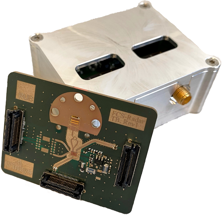
Fig. 1. Photograph of built LO module with the RF frontend highlighted.
Radio telescope requirements
Radio telescope measurements do not easily benefit from a correlation effect as the radar case described by (1). The required LO signal is applied to the receive mixers exclusively, which down-convert the sky's signal. In the case of ALMA, the observed frequencies range from 31–950 GHz [Reference Cliche and Shillue13]. The resulting bandwidth of 911 GHz is divided into 10 bands, each having a dedicated LO assembly [Reference Shillue, Grammer, Jacques, Meadows, Castro, Banda, Treacy, Masui, Brito, Huggard, Ellison, Cliché, Ayotte, Babin, Costin, Latrasse, Pelletier, Picard, Poulin and Poulin11]. This limits the individual tuning bandwidth to 16%–25%, which is surpassed by the 40.1% relative bandwidth of our utilized VCO [Reference Bredendiek, Hansen, Briese and Pohl14]. Generally speaking, each warm cartridge assembly is based on the frequency multiplication of a YTO as described in Section ‘Introduction’, with small modifications based on the desired output frequency. The maximum frequency at the output (including YTO, amplifiers, and warm multiplication) is limited to 121.7 GHz. For all bands surpassing that frequency (band 4–10), a cold frequency multiplier is placed behind the warm cartridge assembly.
While ALMA has been in operation since 2013, another radio telescope, the next generation Very Large Array (ngVLA) is currently in its design stages. Its system conceptual design description has been released in June 2022 [Reference Selina, Murphy, Kusel, Beasley, Allison, Amestica, Archuleta, Bhatnagar, Brandt, Butler, Carilli, Denman, Dunbar, Durand, DuVernay, Cole, Demorest, Erickson, Esterhuyse, Ford, Gerrard, Grammer, Hales, Hiriart, Hunter, Jackson, Kern, Koski, Langley, Lopez, Mangum, Mason, McKinnon, Muehlberg, Morgan, Ojeda, Pokorny, Rao, Romero, Rosen, Rosero, Sadowski, Shillue, Sridharan, Srikanth, Sturgis, Symmes, Swift, Urbain, Walker and Wrobel15]. Therein included is the frequency plan which divides the targeted bandwidth of 1.3–116 GHz into six bands. Band 6, which extends the W-band with its frequency range of 70–116 GHz is of the highest interest to this work. A total of 8 LO frequencies with a spacing of 5.8 GHz are required for that band. They can therefore all be generated as multiples of the intended 2.9 GHz reference frequency.
These LO frequencies are used to down-convert the sky's signal into the baseband which is then sampled at 7 Gsps, creating an overlap between the IF-signals to support calibration. The ngVLA allocates τ sys = 132 fs of total system rms phase noise (per antenna). By applying the factor $\exp({{-\phi ^2\over 2}})$ where ϕ = ω ⋅ τ sys with ω being the maximum radial frequency of 2π ⋅ 116 GHz this amounts to a signal coherence loss of 1% [Reference Thompson, Richard, Moran and Swenson16]. The total system phase noise is equally allocated (in a root sum square sense) to the LO, the digitizer clock, and actual physical jitter of the 18-m antenna structure. The LO modules of the ngVLA therefore need to create the signals with minimum jitter, 76 fs or less, up to an offset frequency of 3.5 GHz [Reference Selina, Kusel, Murphy, Farnsworth and McKinnon17].
Our aim in this work is not to build a module that directly qualifies for the use in ngVLA. Rather, we test the capabilities of our integrated frequency synthesizer presented in [Reference Braun, van Delden, Bredendiek, Schoepfel and Pohl8] in this new context. Therefore, the realized LO module aims to generate frequencies inside the E-band with a very high reference frequency of 5 GHz. The integrated jitter up to an offset frequency of 2.5 GHz should not surpass 76 fs. This results in a continuously observable sky frequency without overlap. As those requirements are similar to the ones presented in [Reference Selina, Murphy, Kusel, Beasley, Allison, Amestica, Archuleta, Bhatnagar, Brandt, Butler, Carilli, Denman, Dunbar, Durand, DuVernay, Cole, Demorest, Erickson, Esterhuyse, Ford, Gerrard, Grammer, Hales, Hiriart, Hunter, Jackson, Kern, Koski, Langley, Lopez, Mangum, Mason, McKinnon, Muehlberg, Morgan, Ojeda, Pokorny, Rao, Romero, Rosen, Rosero, Sadowski, Shillue, Sridharan, Srikanth, Sturgis, Symmes, Swift, Urbain, Walker and Wrobel15, Reference Selina, Kusel, Murphy, Farnsworth and McKinnon17], the realized performance of the E-band LO modules may clarify whether complicated warm cartridge assemblies can be replaced by integrated frequency synthesizers in the future.
Phase noise and jitter fundamentals
Phase noise is not as easily characterized by a single value as for instance a system's output power. This complicates the comparison of different LO-signal sources. Hereafter, we refer to the phase noise as one half of the one-sided spectral density of phase fluctuations with respect to a bandwidth of 1 Hz as defined by IEEE standards [18]. In corresponding tables of publications, the phase noise value at an offset frequency of 1 MHz is regularly given. This is common practice for the open-loop phase noise of VCOs, as it can be easily measured and extrapolated. However, this is not the case for LO-signals provided by a PLL. Additionally, the value at 1 MHz offset frequency does not directly impact the performance of most microwave measurement systems. What has an impact on the SNR however, is the integrated phase error
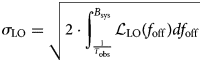
ranging from the subsequently discussed lower integration limit $T_{\rm obs}^{-1}$ to the system's bandwidth B sys. In a radar system, B sys is limited by the anti-aliasing low-pass filter in front of the analog-to-digital-converter (ADC). Alternatively, a radio telescope conducts fixed frequency measurements with a step size of f res. Thereby, B sys can be limited to f res/2. While the upper integration limit can be derived from the intended application, a lower limit of 0 Hz would pose a problem. Observing an oscillator with an f −2-behavior for an infinite amount of time will inevitably cause the measured jitter to increase indefinitely. Therefore, it can and often is limited to the reciprocal of the system's maximum observation time T obs [Reference Dalt and Sheikholeslami19]. The integrated phase error can be converted to the RMS time jitter

which normalizes the phase noise based on the signal's frequency f s, thus allowing for easier comparisons.
Furthermore, it can be derived from (3), that decisive measure is the area underneath the phase noise as a function of the offset frequency. Therefore, the oscillator's free-running phase noise does not directly dictate the σ LO. Whereas, it determines the necessary noise floor of the PLL to achieve a specific σ LO.
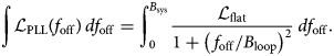
For illustration, we can approximate the closed-loop phase noise of a PLL as a function of f off as

This assumes a constant value ${\cal L}_{{\rm flat}}$ up to the loop bandwidth B loop neglecting 1/f noise close to the carrier and the noise floor for large offset frequencies. Outside the loop bandwidth the phase noise quadratically decreases with the oscillator's open-loop phase noise [Reference Dalt and Sheikholeslami19]. To calculate the corresponding J LO, this equation is first integrated in regards to f off
It should be noted that in this case a lower boundary of 0 can be chosen, because the ${\cal L}_{{\rm PLL}}$ approximation does not converge towards infinity close to the carrier. To minimize the integrated phase error, B loop is chosen as the crossing frequency of the VCO's noise ${\cal L}_{{\rm VCO}}$
 and ${\cal L}_{{\rm flat}}$
 given by
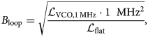
where ${\cal L}_{{\rm VCO, 1\, MHz}}$ is the phase noise of a SiGe VCO at an offset frequency of 1 MHz with a low 1/f noise corner frequency. Furthermore, (6) is solved using

Inserting the result of (6) into equations (3) and subsequently (4) we finally derive a jitter of
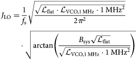
for the approximated PLL. To illustrate the resulting jitter's dependency on the upper integration limit B sys, its behavior is also illustrated in Fig. 2. For increasing B sys it converges towards

which showcases that the phase noise floor of the PLL ${\cal L}_{{\rm flat}}$ has the same impact on the jitter as ${\cal L}_{{\rm VCO}}$
 . Therefore, the use of an YTO can be omitted, if using a PLL with a noise floor of -110 dBc as we will demonstrate in Section ‘Measurement results’.
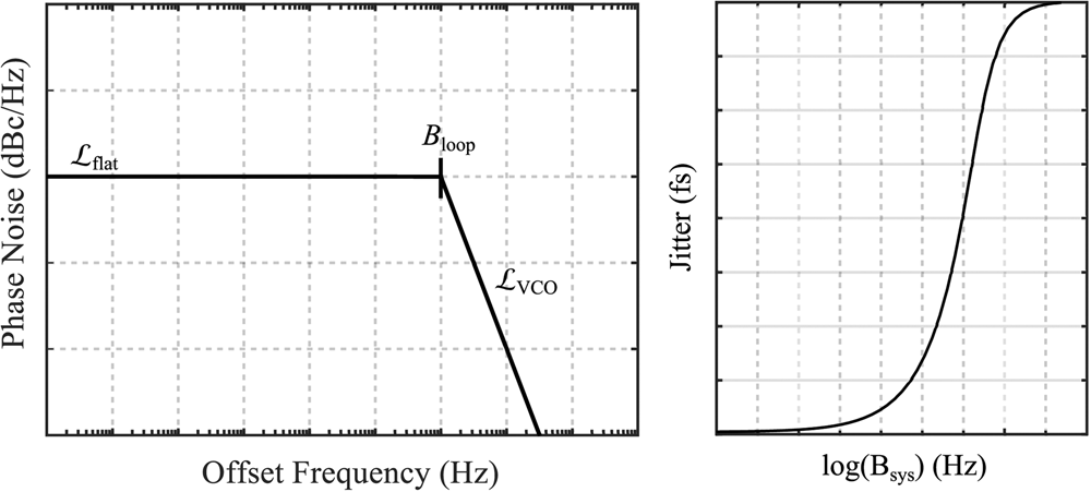
Fig. 2. Illustration of the approximation of the closed-loop PLL phase noise (left) and the resulting jitter as a function of the system's bandwidth (right).
MMIC
The proposed synthesizer was realized on an MMIC in Infineon's B11HFC 130 nm SiGe:C technology with f T = 250 GHz and f max = 370 GHz. It has a size of 1964 × 1448 μm2, and is shown in Fig. 3.
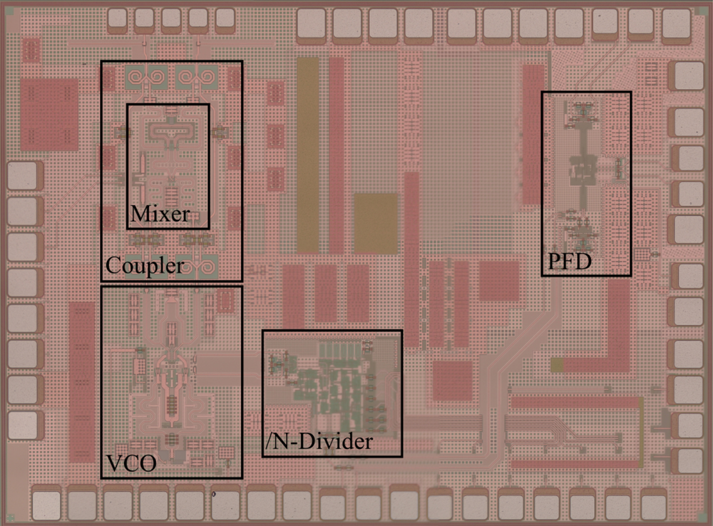
Fig. 3. Photograph of the realized MMIC containing the mixer, coupler, VCO, programmable frequency divider and PFD.
It contains a transceiver including a VCO covering the E-band [Reference Bredendiek, Hansen, Briese and Pohl14], which is necessary to fulfill the demands presented in Section ‘Radio telescope requirements’. This is achieved due to a tunable bandwidth of 31 GHz. The corresponding required tuning voltage ranges from 1.1 V to 9.3 V. With an output power of 7 dBm provided by the VCO, the transceiver provides a transmit output power of approximately -1 dBm measured on-chip. All while simultaneously driving the LO-port of the direct-down-conversion mixer. The minimum open-loop phase noise at an offset frequency of 1 MHz was measured to be −99 dBc/Hz.
The VCO's core is connected to the fully programmable frequency divider [Reference van Delden, Pohl, Aufinger and Musch20]. By using merged emitter-coupled logic in conjunction with inductive peaking, it achieves a maximum input frequency of 94 GHz. Thus, a static frequency division inside the PLL can be omitted. Additionally, the programmability of every integer division factor 12 ≤ N ≤ 259 allows for high flexibility of the reference frequency. Hence, the maximum reference frequency able to cover the E-band is f ref = 5 GHz, which is used for the phase noise measurements in Section ‘Measurement results’. The divider's additive phase noise for a division ratio of 15 and output frequency of 5 GHz is depicted in Fig. 4.
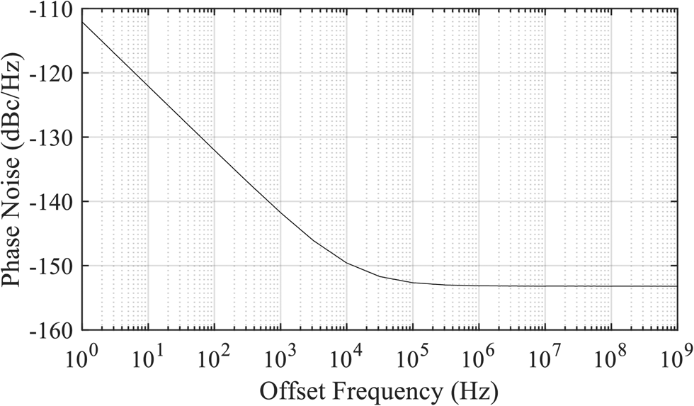
Fig. 4. Simulated additive phase noise of the programmable frequency divider for an output frequency of 5 GHz and a divider value N of 15.
To operate at a high reference frequency of 5 GHz, a highly linear PFD with a high input frequency is used, comparable to [Reference Hasenaecker, van Delden, Jaeschke, Pohl, Aufinger and Musch1]. To achieve those required operating frequencies, the PFD is also implemented in merged emitter-coupled logic, like the programmable divider. The output stage is realized with open-collector outputs designed to drive an external, differential active low-pass filter without the use of a charge pump (CP). A CP is conventionally used to drive the loop filter. It allows for a passive loop filter and thus a fully integrated PLL. However, the use of an integrated loop filter significantly limits the achievable transfer functions and tuning voltages. Additionally, the mismatch of the up and down currents at these high input frequencies would considerably degrade the linearity of the PFD and lead to high dynamic mismatch noise in the PLL [Reference Hasenaecker, van Delden, Jaeschke, Pohl, Aufinger and Musch1]. As is shown in Section ‘Measurement results’, the PFD's additive phase noise does not affect the PLL, due to the f ref of 5 GHz. As described in detail in [Reference Brennan and Thompson21], the additive phase noise of a PFD only increases by 10 dB per decade with increasing reference frequency.
The entire MMIC draws a current of approximately 340 mA from a 3.6 V power supply.
For the reasons mentioned above, the transceiver renounces the use of a CP while using an external active loop filter. Fig. 5 presents the filter's architecture. With the help of simulations, a loop bandwidth of 5.8 MHz with a phase margin of φm = 71° at the center frequency of f s = 75 GHz was chosen to minimize the PLL's jitter. While a higher B loop and φm would have been even better, respectively, we limited the minimum value of C p to avoid problems caused by the op-amp's input capacitance.
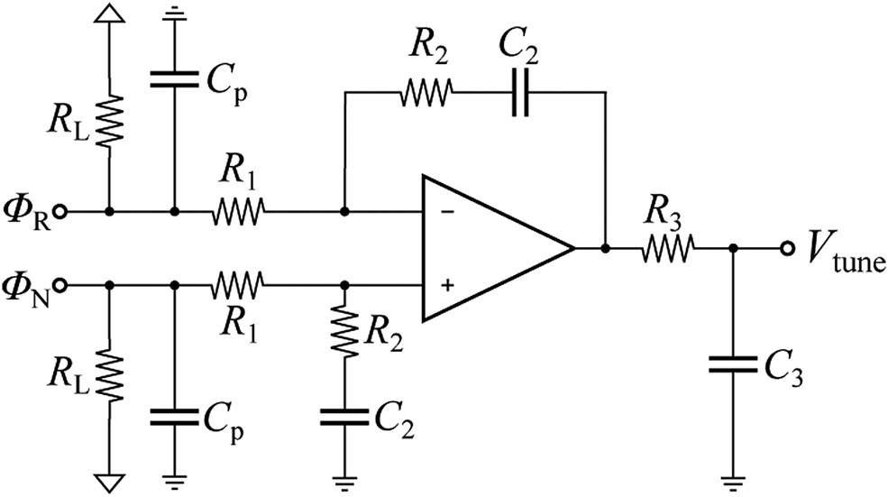
Fig. 5. Schematic of the active loop filter, applying the differential output signal of the PFD directly, without the use of a CP.
LO module
To address the described application, the MMIC presented in Section ‘MMIC’ is utilized inside an LO module. This module consists of two printed circuit boards (PCBs), an RF-frontend, and a control board. Both PCBs are presented in Figs. 6 and 7.
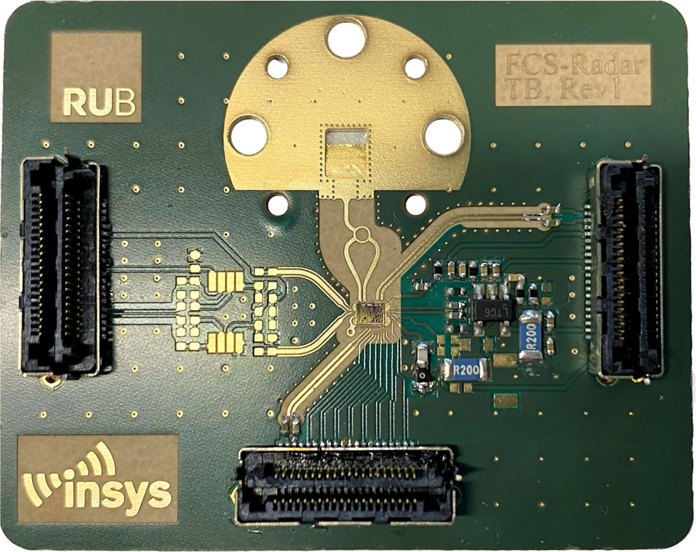
Fig. 6. Photograph of the RF frontend. The MMIC presented in Section ‘MMIC’ is placed inside a cavity and wire-bonded to the PCB. The RF-signal is coupled via a stepped waveguide transition into a WR-12.
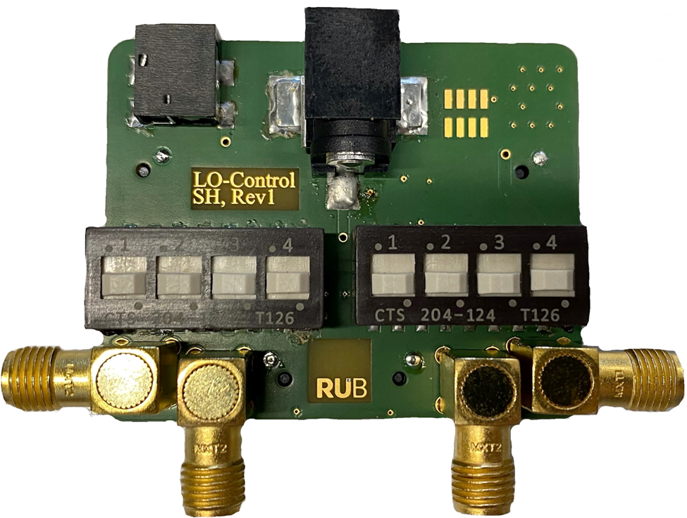
Fig. 7. Photograph of the control board. It generates the necessary supply voltages from 5 V and 12 V, respectively. To change the divider value double-throw dip switches are located on the PCB. SMA connectors are utilized to supply the reference frequency and probe the frequency divider's output.
The RF-frontend was manufactured using Rogers RO3003TM substrate with a thickness of 127 μm. It has relative permittivity of $\epsilon _{{\rm r}} = 3$ and a dissipation factor of tan δ = 0.001 at 10 GHz. It consists of the MMIC, the loop filter, an IF-amplifier for radar operation and a waveguide transition to couple the synthesized LO-signal. The differential signal at the MMIC's output is combined via a rat race coupler. Afterwards, the single-ended microstrip transitions into a surface-integrated waveguide (SIW) and subsequently a WR-12 through air-filled steps based on the concept presented in [Reference Hansen and Pohl22]. As the VCO discussed in Section ‘MMIC’ can cover the full E-band of the WR-12, the used waveguide transition should as well. Therefore, it was designed and optimized in CST Studio Suite. The results of those simulations including the rat-race coupler are presented in Fig. 8. A return loss better than 13.5 dB is achieved for the entire E-band resulting in a maximum mismatch loss below 0.2 dB. The insertion loss is better than 3.2 dB for the entire band and better than 2 dB from 66 GHz on, respectively.
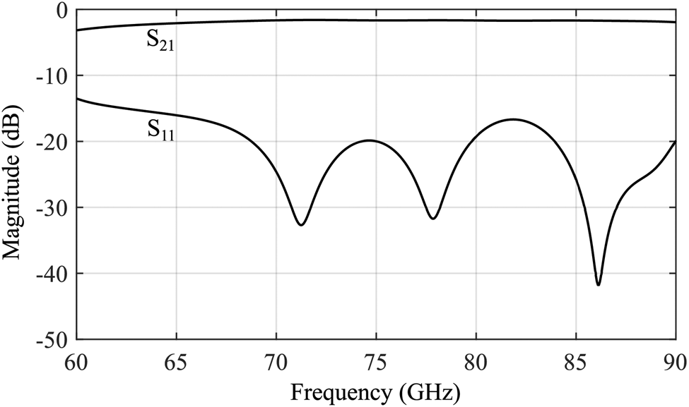
Fig. 8. Simulated transmission S 21 and reflection S 11 parameters of the WR-12 waveguide transition in the entire E-band.
The control board encompasses a 5 V and 12 V power connector to supply the MMIC and loop filter op-amp, respectively. The additional 12 V supply eliminates the need for a DC-DC converter, to keep the signal free from any switching frequencies. LSHM high-speed connectors are used to connect the boards to cope with the used reference and divider frequency. Both can be applied or tapped through SMA-connectors, respectively. The divider value can be adjusted with the double throw dip switches.
To achieve repeatable and reliable results, thermal management of the MMIC must be considered. Therefore, the bare die is placed inside a cavity and glued onto the back plate copper of the RF-frontend with a thickness of 1 mm. Additionally, this copper is in direct contact with the metal enclosure, which can be seen in Fig. 1. This distributes the produced heat over a larger thermal mass, away from the MMIC. Even during constant use, the temperature of the metal enclosure does not surpass 40 $^\circ$ C.
C.
The complete module has a size of 6 × 5 × 2 cm3 and only requires two supply voltages and the reference frequency to generate the low jitter LO-signal provided at the WR-12. In total, it consumes a power of approx. 1.9 W.
Measurement results
To verify the quality of the generated LO signals, phase noise measurements with the realized LO module were conducted. The reference signal of 5 GHz is provided by a phase noise and signal source analyzer (R&S FSWP) that also performs the measurements. Therefore, the coupling bandwidth of the analyzer's internal synthesizers is set to 1 Hz to avoid cancelation of the reference's noise close to the carrier. Since the LO module's generated frequencies surpass the device's maximum input frequency, a W-band extender module (VDI WR10SAX) was used as an external mixer. The SAX is connected to the WR-12 of the module and extends the FSWP's range beyond the needed bandwidth. However, this entails operating the WR10SAX out of its specified frequency range and close to the waveguide's cutoff. Nevertheless, this setup offered the lowest available noise floor, while being able to measure nearly the full range of the generated frequencies.
Firstly, the phase noise at the center frequency is measured and compared to the simulation from 10 Hz to 1 GHz in Fig. 9. This includes the simulated contributions of the single PLL's components. The measurement and simulation are in good agreement, while the measured phase noise is slightly degraded at 100 kHz and 10 MHz. At first the reference dominates the PLL's phase noise from 10 Hz up to an offset frequency of approximately 500 kHz, while the VCO dominates for higher offset frequencies. It has to be noted that the down-conversion signal fed into the SAX is not part of the simulations. Nevertheless, the in-band phase noise is very low compared to the state of the art, with just −111.8 dBc/Hz at an offset frequency of 10 kHz.
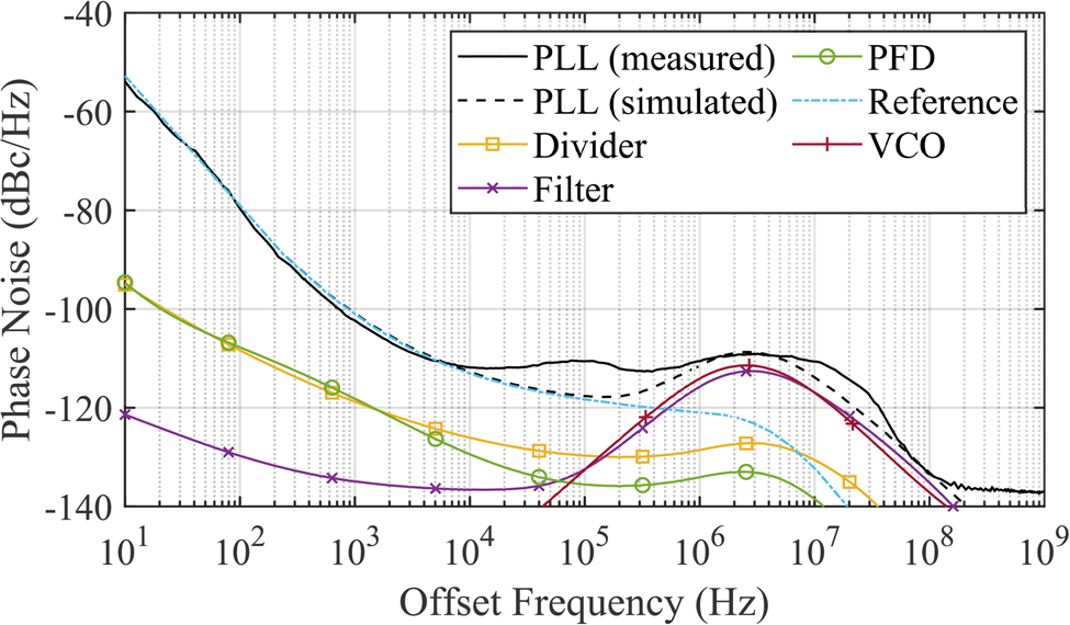
Fig. 9. Measured phase noise at the waveguide port for f s = 75 GHz compared to the simulation. A very low in-band phase noise of −111.8 dBc/Hz at 10 kHz has been achieved. Additionally, the measurement is in good agreement with the simulation, with a slight degradation at 100 kHz and 10 MHz, respectively.
As phase noise measurements typically do, the presented measurement results include a spur reduction of the measurement instrument. To investigate the PLL's spur level, the filtered phase noise is compared to the raw data in Fig. 10. Except for one spur slightly above 10 MHz at approximately −95 dBc, the raw data is spur-free upwards of 1 kHz. Below 1 kHz there are a couple of even smaller spurs caused by e.g. the European line frequency of 50 Hz. Additionally, the phase noise measured at the divider output increased by 20log(15) = 23.52 dB is also included in the Fig. 10. It closely matches the behavior measured at the waveguide. A significant difference is an increased noise floor starting from approximately 40 MHz. This is caused by the noise floor of the frequency divider itself, as the simulated −154 dBc presented in Fig. 3 are also degraded by 23.52 dB. Nevertheless, measuring the divider output via SMA is a viable option up to an offset frequency of approximately 40 MHz, without needing extra measurement equipment capable of frequencies up to 90 GHz. It furthermore validates the measurements conducted at the waveguide.

Fig. 10. Measured phase noise at f s = 75 GHz with and without spur reduction. The raw data is almost identical to the filtered signal, with a small spur above 10 MHz. Additionally, the result when measuring at the divider output is also given. This method offers easier measurements with an increased noise floor above 40 MHz caused by the frequency divider.
To investigate the phase noise performance across the entire E-band frequency range, measurements for all available frequencies were conducted and are depicted in Fig. 11. Therein, the frequencies 70 GHz ≤ f s ≤ 85 GHz were measured at the waveguide. However, due to the undercutting of the WR10SAX's specified frequency range, only a very low amplitude is measured at 65 GHz. As this low amplitude compromises the phase noise measurement, the result at the divider output with its increased noise floor starting at 40 MHz offset is presented instead. All the frequencies exhibit very low in-band phase noise. The variation of the VCO gain K VCO is around 10:1 and causes the differences of loop bandwidth and phase margin across the generated frequencies.

Fig. 11. Measured phase noise at all stabilizable frequencies with f ref = 5 GHz. They all exhibit very low phase noise, while the signal frequency f s = 65 GHz had to be measured at the divider output because of the limitations of the WR10SAX and is therefore limited by the measurement setup above 40 MHz. Simultaneously, the effect of K VCO on the bandwidth and phase margin is visible.
As discussed in detail in Section ‘Phase noise and jitter fundamentals’, the RMS time jitter can be of great interest for trying to characterize and compare phase noise. Therefore, we calculated the jitter at all the generated frequencies. The minimum available offset frequency of 10 Hz was chosen as the lower integration limit. To illustrate the main contribution to the jitter, it was calculated as a function of the upper integration limit. Each frequency's noise floor was extrapolated up to 2.5 GHz to achieve the f step/2 limit discussed in Section ‘Phase noise and jitter fundamentals’. The legitimacy of that extrapolation was validated using a third measurement setup able to measure up to that frequency. Since that setup dominated the phase noise inside the loop bandwidth it was only used for that validation and the results are not shown for clarity. Fig. 12 shows the resulting jitter for the five signal frequencies. It can be seen, that the measured jitter as a function of the upper integration limit shows close resemblance to the theoretical behavior described in (9) and illustrated in Fig. 2. While the reference has an impact close to the carrier, the majority of the jitter is added close to B loop, in accordance to [Reference Dalt and Sheikholeslami19]. An effect not modeled in (9), but observable in Fig. 12, is the finite noise floor starting to become relevant for very high offset frequencies. However, up to 2.5 GHz it does not yet have a significant impact. Additionally, at all signal frequencies, except of f s =65 GHz, the requirements of 76 fs presented in section ‘Radio telescope requirements’ are fullfilled. It should be noted, that the 65 GHz measurement was limited by the equipment, while the steep K VCO also becomes difficult to account for. To improve the results at the low signal frequencies, the feasibility of a loop gain compensation as we presented in [Reference Van Delden, Pohl and Musch23] will be investigated in future works.

Fig. 12. Integrated jitter starting at 10 Hz in dependency of the upper integration limit. The frequencies starting from 70 GHz all exhibit a small enough jitter for the desired application. Only 50–57 fs are reached when integrating to 2.5 GHz for 70–85 GHz.
As a final measurement, the LO module's output power dependent on the signal frequency is characterized. Therefore, the system was connected to a E4418B power meter with a W8486A W-band power sensor, both from Agilent. Furthermore, this measurement also showcases the stabilizable bandwidth in more detail. As depicted in Fig. 13, a step size of 1 GHz was chosen to obtain a smoother measurement curve. The module achieves a stabilizable frequency range of 62 GHz ≤f s ≤ 88 GHz. The maximum measured output power is approximately -6 dBm. As it should be approximately −1 dBm on-chip, this is in good agreement concerning the losses of the bond-wires and the simulated waveguide transition. It can be assumed that the rat-race coupler especially, will exhibit losses a bit higher than the simulations may suggest. While the presented output power is not sufficient for a radio telescope, it should be recalled, that the presented MMIC's output is intended as a monostatic radar transceiver. In that application a high output power would potentially over-saturate the receiver. For the desired application it can be extended with an amplifier in the future.
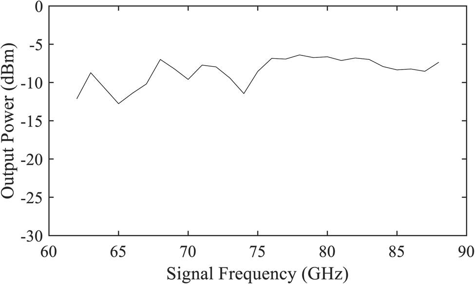
Fig. 13. The measured output power of the module for its frequency range of 62–88 GHz. A maximum power of -6 dBm is reached, which is in good agreement with the monostatic radar transceiver application in mind, the MMIC was initially intended for.
Lastly, the presented measurement results are compared to the state of the art in Table 1. Our presented LO module is able to achieve the lowest jitter from 10 kHz to 100 MHz with just 46 fs, compared to integrated frequency synthesizers in the E- to W-band range. At the same time it exhibits a bandwidth of up to 26 GHz, which is also among the highest. While a traditional warm cartridge assembly can still offer a lower jitter, our presented module has shown the potential to fulfill the requirements of this demanding application. At the same time it offers a significantly decreasing size, cost, and complexity.
Table 1. State-of-the-art frequency synthesizers with high relevance to this work.
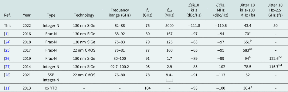
aCould only be integrated up to 10 MHz based on the measurement results.
bGraphically determined by integrating the phase noise measurements.
cIntegrated from 100 Hz to 1 GHz.
dStarting frequency of 500 Hz.
Conclusion
In this article we presented a compact LO module achieving phase noise levels and jitter suitable for radio telescope applications. Therein we achieved a phase noise of just −111.8 dBc/Hz at 10 kHz offset with our integrated frequency synthesizer. This resulted in an RMS time jitter of only 50 fs integrated from 10 Hz to 2.5 GHz at a signal frequency of 75 GHz. The stabilizable frequency range of the module extends from 62–88 GHz, surpassing the 25% relative bandwidth of the modules used inside ALMA. Compared to those state-of-the-art radio telescope modules, ours significantly decreases size, cost and complexity.
Acknowledgements
The authors would like to thank Infineon Technologies AG for fabricating the MMIC. This work was supported in part by the Deutsche Forschungsgemeinschaft (DFG, German Research Foundation) under Project-ID 287022738 TRR 196.
Conflict of interest
The author(s) declare none.
 Tobias T. Braun was born in Duesseldorf, Germany, in 1996. He obtained the B.Sc. and M.Sc. degrees in electrical engineering and information technology from TU Dortmund, Dortmund, Germany, in 2016 and 2019, respectively.
Since 2019, he is pursuing his Ph.D. as a research assistant with the Institute of Integrated Systems at Ruhr University Bochum, Bochum. His current research interests include integrated circuit and system design for automotive applications.
Tobias T. Braun was the recipient of the EuMIC Young Engineer Prize from European Microwave Week in 2021.
 Marcel van Delden was born in Hattingen, Germany, in 1990. He obtained the B.Sc. and M.Sc. degrees in electrical engineering from Ruhr University Bochum, Bochum, Germany, in 2012 and 2015, respectively.
Since October 2013, he has been a research assistant with the Institute of Electronic Circuits, Ruhr University Bochum. His current research interests include the design of integrated mm-wave and digital circuits in ultra-wideband frequency synthesis with highest phase stability.
He was a co-recipient of the EuMIC 2021 Best Student Paper Award.
 Christian Bredendiek was born in Gelsenkirchen, Germany, in 1981. He obtained the Dipl.Ing. and Dr. Ing. degrees in electrical engineering from Ruhr University Bochum, Bochum, Germany, in 2008 and 2014, respectively.
From 2008 to 2014, he was a research assistant with the Institute of Integrated Systems, Ruhr University Bochum. Since 2015, he has been with the Department of Integrated Circuits and Sensor Systems, Fraunhofer Institute for High Frequency Physics and Radar Techniques FHR, Wachtberg, Germany. His current research interests include frequency synthesis, working on system concepts and integrated circuits for various mm-Wave applications.
Dr. Bredendiek was a recipient of the EuMIC Best Paper Award from European Microwave Week in 2012 and a co-recipient of the EuMIC 2021 Best Student Paper Award.
 Jan Schöpfel obtained the B.Sc. and M.Sc. degrees in electrical engineering and information technology from Ruhr University Bochum, Bochum, Germany, in 2014 and 2016, respectively.
Since 2017, he has been with the Institute for Integrated Systems, Ruhr University Bochum, Bochum, Germany. His current research interests include the concepts and integrated circuits for radar sensors for fully autonomous driving.
He was a co-recipient of the EuMIC 2021 Best Student Paper Award.
 Stephan Hauptmeier is pursuing his B.Sc. degree in electrical engineering and information technology from Ruhr University Bochum, Bochum, Germany, since 2019. In 2021, he has started at the Institute for Integrated Systems, Ruhr University Bochum, Bochum, Germany as a working student focusing on component design for D-band applications.
 William Shillue obtained the B.S. degree in electrical engineering from Cornell University, Ithaca, NY, USA, in 1985, and the M.S. degree in electrical engineering from the University of Massachusetts, Fall River, MA, USA, in 1990.
In 1991, he joined the National Radio Astronomy Observatory (NRAO), Green Bank, WV, USA, where he participated in the design and deployment of a 13.7 m satellite earth station in support of the NASA Orbiting-Very-Long-Baseline-Interferometer Project. From 1994 to 2005, he was with NRAO Tucson, where he developed millimeter-wave receivers and instrumentation for the 12 m telescope, and new photonics technologies for the Atacama Large Millimeter Array (ALMA), Antofagasta, Chile. From 2005 to 2012, he was the Team Leader for the ALMA central local oscillator and ALMA photonic local oscillator distribution systems. He has led the NRAO Phased Array Research and Development Program and developed technology concepts for next-generation radio astronomy instrumentation. He is currently a research engineer with NRAO, Central Development Laboratory, Charlottesville, VA, USA.
Mr. Shillue is a member of IEEE Photonics Society and Microwave Theory and Techniques Society.
 Thomas Musch Member, IEEE) was born in Mülheim an der Ruhr, Germany, in 1968. He obtained the Dipl.Ing. and Dr. Ing. degrees in electrical engineering from Ruhr University Bochum, Bochum, Germany, in 1994 and 1999, respectively.
From 1994 to 2000, he was a research assistant with the Institute of High Frequency Engineering, Ruhr University Bochum, where he was involved in system concepts and electronic components at microwave frequencies, mainly in the fields of frequency synthesis and high-precision radar. From 2003 to 2008, he was with Krohne Messtechnik GmbH, Duisburg, Germany. As the Head of the Department of Corporate Research, he was responsible for research activities with the Krohne Group, Duisburg. In 2008, he became a Full Professor of electronic circuits at Ruhr University Bochum. His current research interests include frequency synthesis, radar systems and antennas for microwave range finding, industrial applications of microwaves, and automotive electronics.
 Nils Pohl obtained the Dipl.-Ing. and Dr.-Ing. degrees in electrical engineering from Ruhr University Bochum, Bochum, Germany, in 2005 and 2010, respectively.
From 2006 to 2011, he was a research assistant with Ruhr University Bochum, where he was involved in integrated circuits for millimeter-wave (mm-Wave) radar applications. In 2011, he became an assistant professor with Ruhr University Bochum. In 2013, he became the head of the department of mm-wave radar and high frequency sensors with the Fraunhofer Institute for High Frequency Physics and Radar Techniques, Wachtberg, Germany. In 2016, he became a full professor of integrated systems with Ruhr University Bochum. He has authored or coauthored more than 200 scientific papers and has issued several patents. His current research interests include ultra-wideband mm-wave radar, design, and optimization of mm-wave integrated SiGe circuits and system concepts with frequencies up to 300 GHz and above, and frequency synthesis and antennas.
Dr. Pohl was the recipient of the Karl-Arnold Award of the North Rhine-Westphalian Academy of Sciences, Humanities and the Arts in 2013, and the IEEE MTT Outstanding Young Engineer Award in 2018. He was the co-recipient of the 2009 EEEfCom Innovation Award, Best Paper Award at EuMIC 2012, Best Demo Award at RWW 2015, and Best Student Paper Awards at RadarConf 2020, RWW 2021, and EuMIC 2021. He is a member of VDE, ITG, EUMA, and URSI.


 Open access