


Introduction
Supercapacitors (SCs) are emerging as promising energy storage devices for heavy-duty vehicles, portable electronic devices, hybrid platform buses, load systems for intermittent renewable energy sources, and storing the regenerative braking energy of electric vehicles and light rail. They have potential advantages in fast charging, great cycling stability, operational safety, and high power density [Reference Zhu, Tang, Wu, Shi, Zhu and Meng1, Reference Shao, El-Kady, Sun, Li, Zhang, Zhu, Wang, Dunn and Kaner2, Reference Muzaffar, Ahamed, Deshmukh and Thirumalai3]. In pursuit of SCs with better performance, tremendous progresses have been made on each component in SCs [Reference Shao, El-Kady, Sun, Li, Zhang, Zhu, Wang, Dunn and Kaner2]. As one special component, the electrode materials play an important role in the electrochemical performance of SCs [Reference Xue, Tian, Deng, Huang, Zhu, Pei, Li, Liu and Zhi4].
According to the charge storage mechanism, SCs can be generally classified into two types: electrochemical double layer capacitors (EDLCs) and pseudocapacitors. Specifically, EDLCs store energy via the electric double layer created at the electrode/electrolyte interface mainly based on carbon-based materials. Owing to the large surface area, versatile morphology, excellent electrochemical stability, and electronic conductivity, carbon-based materials such as highly porous graphene [Reference Wang, Pei, Zhao and Dryfe5], graphene-based hybrid composites (GHCs) [Reference Azadmanjiri, Srivastava, Kumar, Nikzad, Wang and Yu6, Reference Azadmanjiri, Srivastava, Kumar, Wang and Yu7], hierarchically porous carbon (PC) [Reference Zhang, Song, Liu, Min, Azadmanjiri, Ni, Niu, Gong, Zhao and Tang8], PC nanosheets [Reference Wen, Kierzek, Min, Chen, Gong, Niu, Wen, Azadmanjiri, Mijowska and Tang9], and carbon flakes [Reference Min, Xu, Li, Ma, Gong, Wen, Chen, Azadmanjiri and Tang10] have received great attention as electrode materials. In contrast to the EDLC, the pseudocapacitor usually shows a higher value of specific capacitance due to the presence of the Faradaic process. Recently, efforts have been widely made in metal oxides (WO3 [Reference Jin, Liu, Jin, Zhang and Bian11], NiO [Reference Yang, Xu, Zhang, Mei, Pei and Zhu12], Co3O4 [Reference Guan, Qian, Wang, Cao, Zhang, Li and Wang13], etc.), metal phosphide of NixCo3−xPy [Reference Song, Wu, Wang, Tang, Chen, Cui and Meng14], metal nitride of TiN [Reference Lu, Wang, Zhai, Yu, Xie, Ling, Liang, Tong and Li15], and metal sulfides (Ni3S2 [Reference Cao, Qian, Zhang, Li, Wang, Wu and Li16, Reference Chen, Li, Wu, Wu, Li, Wu, Liu and Li17], NiS [Reference Yan, Tong, Ma, Tian, Cai, Gong, Zhang and Liang18], Co9S8 [Reference Li, Ding, Huang, Yu, Zhang, Chen, Ramakrishna and Peng19], NixCo3−xS4 [Reference Cao, Tang, Mei and Liu20], etc.) for SCs owing to their inherent redox reaction, leading to high specific capacitances compared with carbonaceous materials. Particularly, as an important candidate of the transition metal sulfide family, nickel sulfide has been featured to own remarkable reversible electrochemical capacitive behaviors, in terms of high levels of energy storage, high electrical conductivity, and power density. Moreover, nickel sulfide has shown high pseudocapacitance due to its multiple valence states and highly redox active Ni element [Reference Gao, Chen, Chang, Chen, Wang, Wu, Xu, Guo and Jiang21]. And substantial progresses in fabricating various nanostructures were witnessed in nickel sulfide, such as porous NiS nanoflake arrays [Reference Yan, Tong, Ma, Tian, Cai, Gong, Zhang and Liang18], Ni3S2 and Co9S8 double-size nanoparticles [Reference Chang, Sui, Qi, Jiang, He, Wei, Meng and Jin22], hierarchically structured Ni3S2/carbon nanotube [Reference Dai, Chien, Lin, Chou, Wu, Li, Wu and Lin23], Ni3S2@MoS2 core shell nanorod on Ni foam [Reference Wang, Chao, Liu, Li, Lai, Lin and Shen24], NiS2 nanocubes [Reference Pang, Wei, Li, Li, Ma, Li, Chen and Zhang25], Ni3S2@Ni composite [Reference Krishnamoorthy, Veerasubramani, Radhakrishnan and Kim26], and Ni3S2 nanorod arrays on Ni-graphene foams [Reference Kamali-Heidari, Xu, Sohi, Ataie and Kim27]. Besides, the enwrapping of conductive layer over the pseudocapacitive materials was another alternative strategy to enhance cyclability of the electrodes, including TiN@C core–shell nanowires (NWs) grown on the carbon cloth [Reference Lu, Liu, Zhai, Wang, Yu, Xie, Ling, Liang, Tong and Li28], CoNi2S4-rGO electrodes fabricated by dip coating of graphene oxide (GO) and the hydrothermal reduction treatment [Reference Gao, Chen, Chang, Chen, Wang, Wu, Xu, Guo and Jiang21], CoMoO4/polypyrrole (PPy) core–shell NW arrays [Reference Chen, Liu, Liu, Wang, Li, Jing and Liu29] and Co9S8@C nanooctahedrons, nanoflowers, and nanospheres [Reference Li, Ding, Huang, Yu, Zhang, Chen, Ramakrishna and Peng19]. Lu et al. [Reference Lu, Liu, Zhai, Wang, Yu, Xie, Ling, Liang, Tong and Li28] synthesized a hybrid electrode consisting of ultrathin carbon shell (∼1.5 nm) on TiN NWs using glucose as the carbon precursor, and the well-designed electrode achieved a remarkable 91.3% retention after 15,000 cycles. Chen et al. [Reference Chen, Liu, Liu, Wang, Li, Jing and Liu29] wrapped about 65-nm-thick PPy firmly onto the outer surface of CoMoO4 NWs as electrode, which exhibited a high areal specific capacitance (approximately 1.34 F/cm2 at a current density of 2 mA/cm) and robust long-term cycling performance (95.2% capacitance retention after 2000 cycles). However, the protective coatings derived from the above methods were often not complete and uniform with poor thickness controllability in nanoscale.
Due to the advantages of three-dimensional conformality, precise sub-monolayer thickness control, large area uniformity, and low processing temperature, atomic layer deposition (ALD)/molecular layer deposition (MLD) is being widely applied in the field of energy conversion and storage devices as a research hotspot [Reference Azadmanjiri, Wang, Berndt and Yu30]. For example, Guan et al. [Reference Guan, Xia, Meng, Zeng, Cao, Soci, Zhang and Fan31] proposed that hollow core–shell NiO–TiO2/CoO–TiO2 electrodes with nanogap show improved areal capacitance, rate capability, and cycling ability compared with the solid electrodes. Herein, we reported well-defined carbon fiber cloth (CFC)/NiS2 electrode materials with “gap shell” PC layer (donated as CFC/NiS2/PC) by means of ALD/MLD methods and their applications in SCs. The as-prepared gap shell structure electrode materials not only inherit the Faraday electrochemical reactivity of NiS2 but also gain the high cyclability compared with mere CFC/NiS2 composites. The gap structure of the PC coating facilitates electrolyte penetration and endows facile ion transport. Meanwhile, the carbon shell protects the NiS2 core from structural deterioration as well as guarantees continuous electron transfer during long charge/discharge cycles.
Results and discussion
Morphology, structure, and composition
Figure 1(a) shows the morphology and microstructure of the acid-pretreated CFC. The treated CFC is composed of numerous interwoven carbon fibers with a smooth surface [Fig. 1(b)]. The diameter of the carbon fiber is appropriately 5 μm. The CFC has been widely used as conductive substrate for flexible electrode or current collector, benefited from its low cost, high electrical conductivity, and mechanical robustness. In addition, the large area of CFC allows relative high loading capability of the active materials. Figure 1(c) shows the typical scanning electron microscopy (SEM) image after Ni metal sputtering and H2S annealing; it can be found that whole carbon fiber surface is covered by nickel sulfide. In addition, nickel sulfide coatings exhibit rough surface with many small bumps. To determine the phase composition of the nickel sulfide shell in composites, X-ray diffraction (XRD) was conducted for pretreated CFC and CFC/nickel sulfide composites, as shown in Fig. 1(d). It can be seen that the convex peak around 25° arises from the CFC substrate. Compared with CFC, several small peaks at 31.6°, 35.3°, 38.8°, and 53.6° corresponding to (200), (210), (211), and (311) planes of NiS2 (JCPDS 11-0099) can be observed in CFC/nickel sulfide composites. In this case, the sputtered nickel metal was mostly transformed into NiS2 after sulfuration process. As a consequence, it can be conjectured that CFC/NiS2 electrode would exhibit good electrochemical performance due to high theoretical specific capacity of NiS2 (>2000 F/g).

Figure 1: SEM images of (a) and (b) the acid-pretreated CFC and (c) NiS2 grown on CFC at high magnification, and (d) XRD patterns of the as-obtained CFC/NiS2 and original CFC.
As a standard chemical state identification technique for most elements in the periodic table [Reference Biesinger, Payne, Grosvenor, Lau, Gerson and Smart32], X-ray photoelectron spectroscopy (XPS) was further applied to investigate the chemical states of the elements in the CFC/nickel sulfide compound. As shown in Fig. 2(a), the CFC exhibits a C 1s peak centered at 284.6 eV, which can be attributed to the C–C bond. Additionally, this binding energy here is used as calibration for other binding energies in the spectrum. As shown in Fig. 2(b), the binding energies of Ni 2p 3/2 and 2p 1/2 for the NiS2 can be detected at around 855 eV and 873 eV, respectively, along with two peaks centered at 860.8 and 879.3 eV, which are assigned to shake-up satellites. Additionally, Ni 2p 3/2 peak can be further deconvoluted into 853.6 and 856.2 eV, belonging to Ni2+ and Ni3+ of NiS2, consistent with previous literature [Reference Tian, Huang, Ai and Jiang33]. Figure 2(c) displays the high-resolution XPS spectrum of S 2p, which can be deconvoluted into three peaks centered at 162.4 eV, 163.7 eV, and 168.5 eV, respectively. The peaks at 162.4 eV and 163.7 eV are associated with the typical metal–sulfur bonds corresponding to the S 2p 3/2 and S 2p 1/2 signal, and the peak at 168.5 eV (S 2p 3/2) is attributed to the presence of sulfate radical ion on the surface of composites. These values are in good agreement with typical S 2p data of NiS2 reported previously [Reference Tian, Huang, Ai and Jiang33]. The peak of 531.8 eV in O 1s spectrum [Fig. 2(d)] agrees with the binding energies of the absorbed OH species on the electrode material surface. No O–Ni bonding signal can be detected, suggesting that no nickel oxide formed during the sulfuration process. The atomic ratio of C:Ni:S:O for CFC/nickel sulfide is also summarized in Table I. It can be seen that the atomic ratio of S:Ni is ∼2.12:1. Based on the above XRD and XPS data, the obtained nickel sulfide compound should be nickel disulfide (NiS2).

Figure 2: High-resolution XPS spectra of (a) C 1s, (b) Ni 2p, (c) S 2p, and (d) O 1s.
TABLE I: XPS compositional ratio of CFC/nickel sulfide compound.

CFC/NiS2/PC electrode was fabricated by ALD of sacrificial Al2O3 and MLD of alucone films onto pristine CFC/NiS2 in the same ALD reactor with subsequent carbonization and etching process, as mentioned in the Experimental Section (Fig. 1). Figures 3(a) and 3(b) display the front-view SEM images of CFC/NiS2/PC. It can be found that after PC coating, the morphology of CFC/NiS2/PC electrode is similar to that of CFC/NiS2 electrode in Fig. 1(c), indicating that the ultrathin protective PC shell has little effect on the microstructure of the NiS2 active materials. Additionally, the photographic image [inset in Fig. 3(a)] illustrates that the prepared NiS2/PC film has rugged mechanical adhesion to the CFC substrate even in case of severe bending, making it possible for further flexible device applications. In addition, the cross-section SEM image [Fig. 3(b)] reveals that the thickness of whole NiS2/PC layer is about 200 nm. X-ray energy dispersive spectroscopy (EDS) mapping was conducted to explore the element distribution in the CFC/NiS2/PC composites, as shown in Figs. 3(c) and 3(d). It can be seen that Ni (green) and S (yellow) elements are distributed in the shell area. The EDS data further confirm the formation of nickel sulfide herein.

Figure 3: (a) SEM image of CFC/NiS2/PC, the inset in panel (a) is the optical image of the CFC/NiS2/PC electrode showing good flexibility. (b) Cross-section SEM image of CFC/NiS2/PC, and corresponding X-ray elemental mappings of (c) S and (d) Ni recorded from an individual fiber in red rectangle in (b).
Transmission electron microscopy (TEM) images of the annealed CFC/NiS2/Al2O3/alucone and CFC/NiS2/PC are recorded in Figs. 4(a)–4(d) to further elucidate their microstructures. It can be seen that the annealed CFC/NiS2/Al2O3/alucone exhibits a sandwich layered structure [Fig. 4(a)], in which the Al2O3 interlayer layer is embedded parallel between NiS2 and annealed alucone coating with the thickness of ∼20 nm. Figure 4(b) clearly shows the core–shell structure of CFC/NiS2/PC, indicating that the carbon layer has uniformly wrapped on the surface of CFC/NiS2. No gap can be observed in Fig. 4(b). It is attributed to the soft nature of PC layer, leading to the easy adhesion to the surface of CFC/NiS2. After etching, the Al2O3 sacrificial layer (ASL) disappears in the sample, indicating that Al2O3 is removed and then the gap is formed between PC and Ni2S. Figures 4(c) and 4(d) show the high-magnification TEM images of a typical carbon coating in different positions with a thickness of ∼30 nm. It should be noted that the as-deposited MLD alucone is around 100 nm-thick and the thickness of hybrid film shrinks obviously after annealing due to the decomposition of organic component and structural collapse at high temperatures [Reference Liang, Yu, Li, Jiang and Weimer34]. In addition, CFC/NiS2 exhibits different shapes with the curved-type [red dotted line in Fig. 4(c)] or regular straight type [red dotted line in Fig. 4(d)]. However, it is found that carbon protective coating can be uniformly formed on the whole CFC/NiS2 substrate with nearly the same thickness in different positions. This can be ascribed to the high conformality characteristics of MLD method. Also, the porous PC structure can be confirmed by the N2 adsorption–desorption isotherms. The Brunauer–Emmett–Teller (BET) specific surface area increases from 6.30 to 16.84 m2/g after the formation of PC on CFC. Based on the mass ratio of PC to CFC, porous PC shows a larger BET specific surface area of ∼372.22 m2/g. Although the formation of carbon protective coating on the energy storage device electrode was reported previously [Reference Li, Wang, Zhou, Wang, Ba, Li, Huang and Liu35], the carbon coatings could not be controlled uniformly at nanoscale like ALD or MLD. In a view of architecture, the carbon shell in CFC/NiS2/PC might play as a protective layer for active materials and an enhanced conductor for electron transport [Reference Ma, Jing, Fan, Hou, Su, Fan and Shao36].
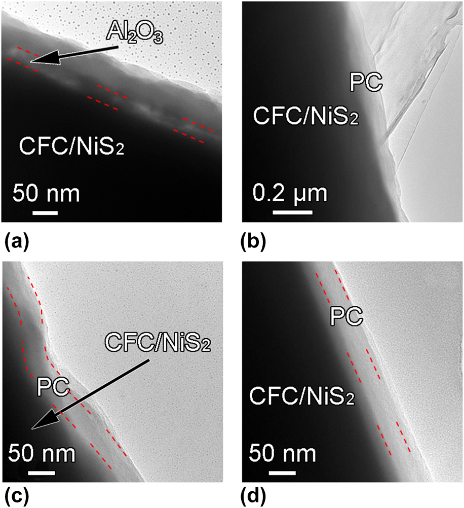
Figure 4: (a) TEM images of the CFC/NiS2/Al2O3/alucone after annealing, (b), (c), and (d) TEM images of CFC/NiS2/PC electrode with various magnifications and at different positions.
Electrochemical properties of electrodes
To study the electrochemical performance of the CFC/NiS2, CFC/NiS2/PC, and CFC/NiS2/PC without ASL, cyclic voltammetry (CV) and galvanostatic charge–discharge (GCD) measurements were performed by using a three-electrode system in 2 M KOH aqueous electrolyte. The CV curves for these three samples are compared at the scanning rate of 50 mV/s in Fig. 5(a). A pair of redox peak can be clearly observed in the range of 0–0.6 V for all the samples, suggesting the battery-type electrochemical behavior. The faradic reversible reaction of NiS2 is based on the surface redox mechanism of Ni2+ ↔ Ni3+ mediated by hydroxide ion under alkaline conditions, according to Eq. (1) [Reference Pang, Wei, Li, Li, Ma, Li, Chen and Zhang25, Reference Ni, Wang, Cheng, Li, Guan, Gu and Huang37].
 $${\rm{Ni}}{{\rm{S}}_2} + {\rm{O}}{{\rm{H}}^ - } \leftrightarrow {\rm{Ni}}{{\rm{S}}_2}{\rm{OH}} + {{\rm{e}}^ - }\quad ,$$
Figure 5: (a) CV curves of CFC/NiS2, CFC/NiS2/PC without ASL, and CFC/NiS2/PC in 2 M KOH at a scan rate of 50 mV/s. (b) GCD curves for CFC/NiS2, CFC/NiS2/PC without ASL, and CFC/NiS2/PC at a current density of 5 A/g. (c) GCD curves of CFC/NiS2/PC for different current densities. (d) Specific capacitance versus current density curve for CFC/NiS2, CFC/NiS2/PC without ASL, and CFC/NiS2/PC.
CFC/NiS2 (blue curve) and CFC/NiS2/PC (red curve) exhibit nearly the same capacitance, as indicated with the similar enclosed area of CV curves. However, the CFC/NiS2/PC without ASL (black curve) electrode shows a much smaller capacitance. It can be ascribed to the fact that direct deposition of protective layer on active material would injure the contact of active material with electrolyte. Therefore, it is very important to introduce a gap area between protective layer and active material. Figure 5(b) compares the GCD curves of the CFC/NiS2, CFC/NiS2/PC without ASL, and CFC/NiS2/PC at a current density of 5 A/g. Apparently, the CFC/NiS2/PC electrode shows the largest capacitance with the maximum discharge time (70 s), while CFC/NiS2/PC without ASL electrode exhibits a very small capacitance. We further measured GCD curves for all samples at different current densities of 1, 2.5, 5, 7.5, 10, and 20 A/g. Each charge and discharge curve for CFC/NiS2/PC has a good symmetry and a non-linear nature, further revealing a reversible faradic behavior, as shown in Fig. 5(c). The specific capacitances (C g) calculated from the GCD curves for CFC/NiS2/PC are determined to be 1034.6, 920.2, 847.6, 801.2, 770.7, and 697.6 F/g at current densities of 1, 2, 5, 10, and 20 A/g, respectively. Figure 5(d) shows the relationship between the specific capacitance and the current density for all the samples. The C g values under all current densities of the CFC/NiS2/PC (red curve) are higher than those of the CFC/NiS2 (blue curve) and CFC/NiS2/PC without ASL (black curve). The capacitances for the CFC/NiS2/PC electrode are almost the same as pure CFC/NiS2 electrode and nearly 8 times of CFC/NiS2/PC without ASL electrodes at 1 A/g. More importantly, CFC/NiS2/PC exhibits an excellent rate capability with capacitance retention of about 67% when increasing the current density from 1 to 20 A/g, which is much better than CFC/NiS2 of 55% and CFC/NiS2/PC without ASL of 10%.
Figure 6(a) shows CV curves of the CFC/NiS2/PC electrode at various scan rates ranging from 5 to 100 mV/s (potential window: 0–0.6 V). It is clear to see that the anodic peaks shift to positive potential, while the cathodic peaks shift to negative potential with increasing scan rate. The phenomenon presented above can be attributed to the following reasons. In a general way, the higher scan rate stimulates the limitation of the ion diffusion rate, which will lead to insufficient fast electronic neutralization during rapid redox reactions [Reference Xing, Zhu, Li and Jiao38]. Additionally, all the CV curves for the CFC/NiS2/PC exhibit a basic symmetrical shape, implying its good reversibility and rate capability. To further elaborate the long-term cycle capability of the prepared electrodes, the cyclic stability test was carried out at 10 A/g, as shown in Fig. 6(b). CFC/NiS2 electrode exhibits extremely poor cyclability and only retains 38.1% of initial capacitance after 2000 cycles with the capacity fading from 625 to 238 F/g. In our previous study [Reference Cao, Qian, Zhang, Li, Wang, Wu and Li16], it has been demonstrated that nickel sulfide is converted to nickel hydroxide during electrochemical cycling with dramatic volume change, resulting in porous structure. As a result, some active materials are peeled off from the electrode, leading to the degradation of capacitance of nickel sulfide electrode. Therefore, poor cycling stability was observed in previous literature [Reference Krishnamoorthy, Veerasubramani, Radhakrishnan and Kim26, Reference Zhou, Cao, Zeng, Shi, Zhu, Yan, Liu, Wang and Zhang39, Reference Qi, Chang, Sui, He, Meng, Wei, Ren and Jin40]. With the help of gap shell PC protection, a capacitance of 520 F/g can be achieved for the CFC/NiS2/PC nanocomposites after 1000 cycles. After extended cycling for another 1000 cycles, ∼57.35% of the initial capacitance can be maintained, showing its much higher cycling stability than only CFC/NiS2. All the above tests indicate that the gap shell is a promising candidate to improve electrode capacity and cyclability toward SC applications.

Figure 6: (a) CV curves of CFC/NiS2/PC at different scan rates and (b) cycling performance of CFC/NiS2 and CFC/NiS2/PC electrodes at a current density of 10 A/g for 2000 cycles in a 2 M KOH aqueous electrolyte.
Theoretically, electrochemical performance is largely associated with ion diffusion and charge transfer process [Reference Song, Wu, Wang, Tang, Chen, Cui and Meng14], the superior capacitive performance of CFC/NiS2/PC electrode mentioned above can be explained as the following factors. The carbon protective layer directly formed on active materials would act as a barrier layer for electrolyte contacting, resulting in capacity deterioration of CFC/NiS2/PC without ASL electrodes [Figs. 5(a) and 6(b)]. Introduction of gap between the carbon coating and NiS2 allows the active material to be completely contacted with the electrolyte, maintaining the electrochemical reactivity of nickel sulfide. Thus, the uniform MLD carbon shell protects the NiS2 core active material from structural deterioration and volume change within prolonged electrochemical cycles [Reference Guan, Xia, Meng, Zeng, Cao, Soci, Zhang and Fan31], improving the long-term cyclability. In such a case, when gap shell nanostructure is introduced in CFC/NiS2/PC electrode, the long-term cycling stability of the sample is greatly enhanced with still remaining relatively high capacitance.
Conclusions
In summary, we have demonstrated a convenient strategy for construction of NiS2 active material on CFC using facile sputtering and annealing approaches. A novel gap shell structure with ultrathin (30 nm) and conformal PC coating has been successfully constructed through ALD and MLD processes with following annealing and etching. The as-obtained CFC/NiS2/PC electrode reaches highest capacitance of 1034.6 F/g at a current density of 1 A/g with superior rate capability of 67% (from 1 to 20 A/g). In addition, the cycling stability of CFC/NiS2/PC composite is enhanced by 50% compared with original CFC/NiS2/PC electrode after 2000 cycles at the current density of 10 A/g. It can be demonstrated that the gap-PC coating not only maintains the electrochemical reactivity of nickel sulfide but also guarantees prolonged electrochemical cycles by providing a protective layer with a buffer area for volume change. Thus, the proposed CFC/NiS2/PC composite with gap shell structure represents a promising route to achieve high-performance SCs with long-time cyclability, flexibility, high energy density, and rate capability.
Experimental section
Pretreatment of CFC
The commercial CFC was firstly cut into 1 cm × 2 cm and then immersed in mixed acid solution (HNO3/H2SO4 = 3:1) before use. Acid treatment was used to enhance the hydrophily of CFC. Afterward, CFC was washed with acetone, isopropanol, ethanol, and deionized water in an ultrasonic bath for 5 min, respectively. Finally, CFC was dried in the air atmosphere.
Synthesis of CFC/NiS2/PC electrode
The fabrication process of CFC/NiS2/PC is illustrated in Fig. 7. Nickel metal was sputtered using a highly pure Nickel target in a Quorum Q150TS coater (Quorum Technologies Ltd., U.K.) onto both sides of the as-prepared CFC for 10 min. Then, it was annealed in H2S (10% H2S–90% N2) atmosphere at 400 °C for 1 h to obtain CFC/NiS2. The CFC/NiS2/PC was fabricated by the ALD, MLD, annealing, and etching processes. ASL was first deposited on the as-prepared CFC/NiS2 by ALD, which was performed at 250 °C for 200 cycles, using Al(CH3)3 (TMA) and H2O as the reactants. Subsequently, alucone hybrid film was grown on the surface of the above product by MLD at 200 °C for 150 cycles, where TMA and fumaric acid precursors were maintained at 25 °C and 172 °C, respectively. For each MLD cycle, the pulse time and purging time for TMA and fumaric acid precursors were 0.5 s/6 s and 4 s/10 s, respectively. After the MLD process, the CFC/NiS2/Al2O3/alucone sample was obtained, and carbonization of MLD alucone coating was conducted in a tube furnace at 700 °C for 1 h with 150 sccm H2 (5% H2–95% N2) flow, in which alucone hybrid film was transformed into the composite of alumina and carbon [Reference Kong, Chen, Cao, Wang, Li, Li and Zhou41]. Finally, the annealed sample was etched in a 2 M KOH solution to remove all Al2O3, then the CFC/NiS2/PC with gap was obtained. For comparison, CFC/NiS2/PC without Al2O3 sacrificial layer (denoted as CFC/NiS2/PC without ASL) was also prepared as control sample by the similar process without ALD Al2O3 deposition procedure.

Figure 7: Schematic illustration of the fabrication of CFC/NiS2/PC.
Materials characterizations
The morphologies and element distributions of the samples were identified using field emission SEM (Ultra 55; ZEISS) and TEM (Tecnai G2 F20 S-TWIN, FEI). XRD (D/MAX 2000; Rigaku) was used to identify the crystalline phase present in the CFC/NiS2 in diffraction angles of 10°–80°. XPS data were obtained using an XPS (Thermo Fisher K-Alpha) with standard Al Kα (1486.7 eV) X-ray source. The BET specific surface area was measured by nitrogen adsorption–desorption isotherms.
Electrochemical measurements
The electrochemical performance of CFC/NiS2/PC electrode was investigated by CV and GCD measurements in a three-electrode electrochemical cell by an electrochemical workstation (CHI600E). The as-prepared CFC/NiS2/PC can be directly used as working electrode without any additives. 2 M KOH aqueous solution was used as the electrolyte. The counter and reference electrodes were platinum wire and Ag/AgCl, respectively.
Specific gravimetric capacitances (C g) were calculated from the GCD curves using Eq. (2).
 $${C_{\rm{g}}} = {{I \times \Delta t} \over {m \times \Delta V}}\quad ,$$
where I, Δt, m, and ΔV are the discharge current density (A), the discharge time (s), the mass of the active materials (g), and the operating voltage window of GCD curves (V), respectively.
Acknowledgments
This work is supported in part by the Natural Science Foundation of China (51802150, 51721001, and 51571111) and Jiangsu Province (BK20161397 and BK20170645), a grant from the State Key Program for Basic Research of China (2015CB921203), and China Postdoctoral Science Foundation (2017M611778).


