


Introduction
Industry 4.0 propels the manufacturing industries away from mass production and toward mass customization to meet customers’ needs with multiple product variants (Daneshmand et al., Reference Daneshmand, Noroozi, Corneanu, Mafakheri and Fiorini2022; Dolgui et al., Reference Dolgui, Sgarbossa and Simonetto2022). Human–robot collaboration can merge the flexibility of humans and the repetitiveness of robots to enhance the overall system capabilities (Inkulu et al., Reference Inkulu, Bahubalendruni, Dara and SankaranarayanaSamy2022). This revolutionary paradigm lets engineers work in real time with the latest digitalized technologies like IoT, cloud, AI, and cyber-physical systems (Ghosh et al., Reference Ghosh, Ullah and Kubo2019; Stojadinovic et al., Reference Stojadinovic, Majstorovic and Durakbasa2021).
Smart manufacturing cannot be accomplished without the use of flexible robotic assembly (Ying et al., Reference Ying, Pourhejazy, Cheng and Wang2021). An effective automated assembly plan can assist manufacturers under colossal pressure to produce and market products faster to meet the demands (Rashid et al., Reference Rashid, Hutabarat and Tiwari2012). Assembly design is said to be complete when product information and an assembly design co-exist (Hui et al., Reference Hui, Dong, Guanghong and Linxuan2007). Developing an optimal feasible assembly sequence plan (OFASP) for a new product variant in low volume is challenging because of the high cost involved in the designing phase. The assembly planning phase accounts for the majority of the cost and time (20%–40%) of overall production estimates; an OFASP can significantly reduce assembling cost and time (Whitney, Reference Whitney2004; Bahubalendruni and Biswal, Reference Bahubalendruni and Biswal2016). When the number of predicates (liaison predicate, assembly interference predicate, stability predicate, and mechanical feasibility predicate) increases, the solution becomes more acceptable (Bahubalendruni and Biswal, Reference Bahubalendruni and Biswal2018). For any product with an “n” number of parts, there can be “n!” possible linear assembly sequences (Ghandi and Masehian, Reference Ghandi and Masehian2015b). The assembly planners should establish the assembly relations and attributes before extracting the assembly predicates (Tseng et al., Reference Tseng, Li and Chang2004). The application of the assembly predicates drastically lowers the number of feasible assembly sequences (De Fazio and Whitney, Reference De Fazio and Whitney1987; De Mello and Sanderson, Reference De Mello and Sanderson1989). The ASP's effectiveness can also be increased by employing a stable subset identification technique (Murali et al., Reference Murali, Deepak, Raju and Biswal2019). Several researchers have worked on extracting assembly constraints and relations from virtual CAD models; these constraints and assembly relations are used to validate assembly sequences’ feasibility (Pan et al., Reference Pan, Smith and Smith2006; Ben Hadj et al., Reference Ben Hadj, Trigui and Aifaoui2015). Literature (Kumar et al., Reference Kumar, Bahubalendruni, Prasad, Ashok and Sankaranarayanasamy2022) has suggested an automated way to get the geometric feasibility through a path with no collisions at an angle. A rule-based geometry-enhanced ontology modeling and reasoning framework are suggested to deal with the customized and digitalized manufacturing environment (Qiao et al., Reference Qiao, Qie, Zhu, Zhu and Anwer2018).
Researchers used artificial intelligence (AI) techniques for their simplicity to generate optimal assembly sequences for various objective functions with a high convergence rate (Deepak et al., Reference Deepak, Bala Murali, Bahubalendruni and Biswal2019; Su et al., Reference Su, Mao and Tang2021). AI methods like breakout local search (Ghandi and Masehian, Reference Ghandi and Masehian2015a), firefly algorithm (Zhang et al., Reference Zhang, Yuan and Zhang2016), advanced immune system (Bahubalendruni et al., Reference Bahubalendruni, Deepak and Biswal2016), machine learning (Cao et al., Reference Cao, Mo, Wan and Deng2018), particle swarm optimization (Wang and Liu, Reference Wang and Liu2010; Ab Rashid et al., Reference Ab Rashid, Tiwari and Hutabarat2019), ant colony optimization (Han et al., Reference Han, Wang and Tian2021), genetic algorithm (Wu et al., Reference Wu, Lu, Lu, Xu and Liu2022; Lu et al., Reference Lu, Wong and Fuh2006), rule-based reasoning (Kroll et al., Reference Kroll, Lenz and Wolberg1989; Lin et al., Reference Lin, Tai, Chen and Alec Chang2007), neural network (Chen et al., Reference Chen, Hsu, Hsieh and Tai2010), simulated annealing (Murali et al., Reference Murali, Deepak, Bahubalendruni and Biswal2017), and psychoclonal algorithm (Tiwari et al., Reference Tiwari, Prakash, Kumar and Mileham2005). Sometimes, combining different methods like the advanced immune system and GA (Gunji et al., Reference Gunji, Deepak, Bahubalendruni and Biswal2017) and neuro-fuzzy by Zha (Reference Zha2001) also provides the optimal solutions faster. Reinforced learning can search for assembly sequences from many solutions and regression, and neural networks can improve the solution faster (Watanabe and Inada, Reference Watanabe and Inada2020).
Aside from the AI technique, a few researchers developed heuristic-based mathematical models (Givehchi et al., Reference Givehchi, Ng and Wang2011; Gulivindala et al., Reference Gulivindala, Bahubalendruni, Varupala and Sankaranarayanasamy2020). Due to the limited information available about the tool and robotic gripper in assembly relation data (liaison and assembly interference data) in the previous work. The solutions derived by utilizing these optimization algorithms are often not optimal and are practically not feasible. Moreover, AI techniques must search the entire solution space to arrive at the optimal solution.
The cost function can be reduced by implementing robotic assembly to minimize the orientation, the number of tool changes, and the length of paths (Rodríguez et al., Reference Rodrıguez, Nottensteiner, Leidner, Kaßecker, Stulp and Albu-Schäffer2019). Many researchers focus on tool selection or assignments by incorporating expertise-based or knowledge-based approaches (Yin et al., Reference Yin, Ding, Li and Xiong2003; Wu et al., Reference Wu, Prabhu and Li2011). Wilson et al. explain the tool representation that includes the tool use volume and the minimum free space in an assembly to apply the tool (Wilson, Reference Wilson1998). The author also categorized the tools based on their application (before, after, and during assembling).
Table 1 delineates a comparative analysis of cited articles and the proposed method. It can be observed from Table 1 that most of the existing literature considered only part attributes and ignored the tools. Due to this, the solution may not be practically feasible. In the current research, tool geometry is also considered for assembling a component to ensure practical feasibility. A novel concept named the tool integrated assembly interference matrix (TIAIM) is proposed.
Table 1. Comparative analysis of the cited literature

NC, not considered; C, considered.
OFASP without considering tooling
A list of preconditions (given below) has been adopted to simplify complex assembly planning-related problems.
1. The parts and tools used for the assembly operations are rigid; no change in size and shape is permitted during the assembly operation.
2. All the parts of the product are considered for the assembly operation.
3. The stability of the components within the assembly is not evaluated.
4. The parts have been assembled linearly.
5. The assembly operation is considered the reverse of disassembly sequence planning to ease assembly interference testing.
6. While generating the TIAIM, the moveable parts are replaced by a combined geometry of the tool and the part.
7. This article considered the number of direction changes as the optimal criteria.
The proposed method that generates the OFASP without considering tooling is presented in Figure 1, which first processes the assembly relations data and generates the assembly sequence plan for a specific objective function. The conditions through which the input data is processed noted as Q1, Q2, Q3, and Q4 are depicted in Table 2. The assembly relation data can produce a stable and feasible solution. In many cases, the assembly jigs/fixtures may be used to obtain the stability of any component.

Fig. 1. Structural outline of the proposed method.
Table 2. Description of the conditions used in this method

The establishment of the mathematical relationship is the fundamental step. Boolean representations (0, 1) are being used to determine whether there is contact or geometrical interference. The assembly relations used for OFASP are given in Table 3 with the retrieval process. The current research uses CATIA API (application program interface) to interface with CAD models to extract the assembly attribute data stated in Table 3.
Table 3. Representation and retrieval of assembly relations

Moreover, the clash test was performed in the CATIA environment to acquire the assembly relations, that is, liaison and assembly interference relations. There are three ways the outputs display, namely contact (=0), clearance (<0), and clash (>0) while performing the clash test. So, the contact analysis process records the conflict elements having a value equal to zero. However, the retrieval system called snap class analysis, as shown in Table 3, reads the conflict elements having values other than zero and tests for assembly interference along the cartesian directions through iteration. Equations (1)–(3) validate the OFASP using the above-mentioned assembly relations.
 $$\eqalign{& {\rm AS}[ 2 ] = P_i + P_j \; \forall \;i\ne j, \cr & {\rm If}\; {\rm LM}( P_i,\ P_j) = 1,} $$
where i, j ∈ (1, 2, 3,…n)
 $$\eqalign{& {\rm AS}[ k ] = {\rm AS\ }[ {k-1} ] + P_j, \cr & {\rm If}\ {\rm LM}( P_i, \ P_j) = 1; \;P_i\in {\rm AS\ }[ {k-1} ] \; \forall \;i\in k-1, \cr & {\rm If} \ \mathop \sum \limits_{i = 1}^{k-1} {\rm AIM}( {\rm dir}, \ P_j, \ P_i) = i-1,} $$
where  ${\rm dir}\in ( {1, \;2 , \ldots 6} )$
 $$\mathop \sum \limits_{i = 1}^n ( {{\rm DC}_i} ) _{\min}, $$
where n is the number of parts of a product and DCi is the number of direction changes.
Implementation
An optimal solution is needed to find out without considering the tooling to acknowledge the influence of tooling in generating OFASP. Different assembly relations needed to be extracted, such as a liaison matrix, an axis-aligned bounding box with part geometry data, and assembly interference matrices. Figure 2 depicts a 3D CAD (CATIA platform) model named bench vice consisting of seven components. The necessary assembly relations, such as the liaison matrix (contact information about the parts of a product) and assembly interference matrix along six cartesian directions, are extracted through the CATIA environment with the help of programmed macros. Furthermore, the proposed algorithms for generating optimal assembly sequence planning are also tested using the same environment.

Fig. 2. 7-part bench vice assembly.
The liaison matrix (LM) is extracted by following the necessary conditions given in Eq. (1). Table 4 represents the result LM for the above CAD model. The DMU (Digital Mock-Up) optimizer provided the bounding box values. Table 5 shows the AABB for the 7-part bench vice, including the minimum and maximum coordinates along the three dimensions (X, Y, and Z).
Table 4. Liaison matrix for the bench vice

Table 5. Axis-aligned bounding box (AABB) of part geometry

Table 6 presents the geometric feasibility (GF) through interference matrices along with ±X, ±Y, and ±Z directions. After extracting all the essential data, the OFASP, as shown in Table 7, is generated by employing the optimality criteria.
Table 6. Assembly interference matrices

Table 7. Optimal feasible assembly sequence plan (OFASP)

Practical infeasibility of solution
The generated optimal assembly sequence plan is going to verify its feasibility by considering tooling. Figure 3 tests whether the generated OFASP is feasible or not by considering assembly tools (screwdrivers) and robotic grippers (grippers). Additionally, the construction of the generation of feasible and infeasible subsets is broken down into individual steps and depicted in Figure 3.

Fig. 3. Practical infeasibility of the generated OFASP.
Figure 3a indicates that the gripper attached to part 3 can be assembled to part 1 (base part) along the (−Z) direction. Similarly, a screwdriver affixed with part 2 can be appended to the (1-3) subset along a collision-free path, as shown in Figure 3b. Part 4 can be assembled to form a (1-3-2) subset along the (−Z) direction (see Fig. 3c). However, the subset (1-3-2-4-5) becomes infeasible as a collision occurs while positioning part 5 to part 4, as displayed in Figure 3d.
Figure 4 provides more clarity regarding the occurrence of interference between the appended parts 4 and 5. Figure 4a shows that part 5 can be assembled to its appropriate location when the presence of the gripper is ignored. However, part 5 cannot be appended to the (1-3-2-4) subset as the gripper is interfering with part 4, as indicated by Figures 3d, 4b. The interference (with a clash value of −0.48) during assembling is observed between the tool holding the appended part (part 5) and the pre-existing part (part 4). Thus, the subset (1-3-2-4-5) becomes infeasible as a collision occurs while positioning part 5 to its final position.

Fig. 4. Clash test results between parts 4 and 5.
Although the OFASP generated by the traditional approach is theoretically valid, it cannot be applied to real assembly-based industrial applications due to the non-consideration of the tool predicate.
Generation of TIAABB and TIAIMs
It is evident that improved assembly sequence planning should be designed for the actual case situations. The proposed method considered a novel assembly attribute by considering tool geometry. The soundness of the proposed approach is validated using a 13-part 3D CAD model. Figure 5 shows the assembled and exploded view of a 13-part CAD product.
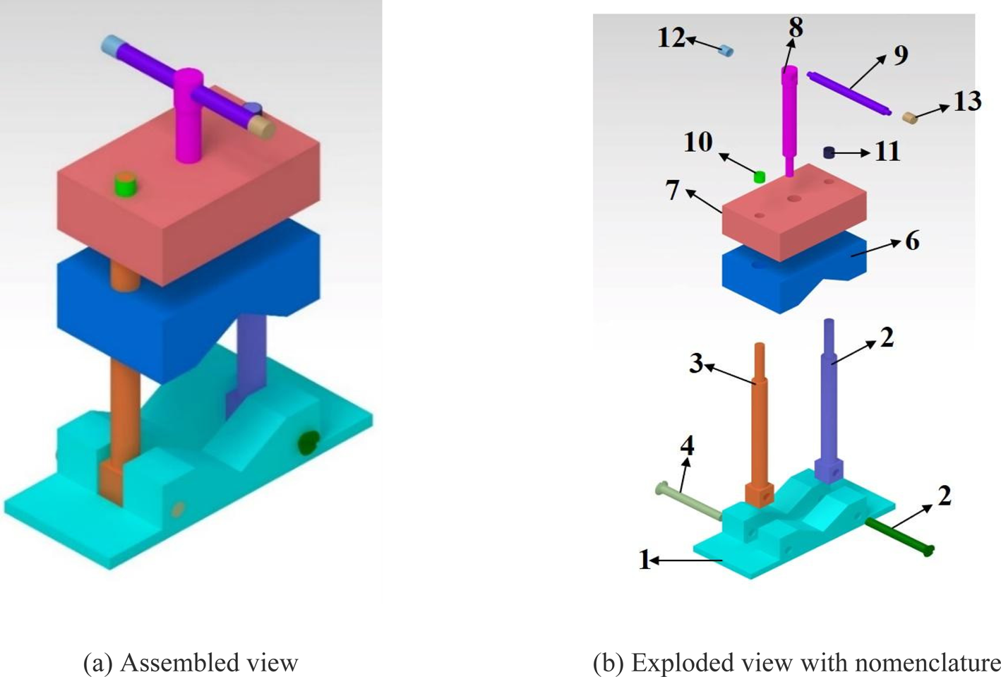
Fig. 5. 13-part CAD model.
The LM, as shown in Table 8, describes the contact information of the parts of a product. The bounded box that is used for generating OFASP in the previous method is not competent enough to deliver a solution related to real-life assembly sequence planning problems. Therefore, the typical bounding box of the part needs to be upgraded to a tool or gripper-integrated axis-aligned bounding box. We can observe that the parts which are needed to be appended require to design along with the assembly tool or robotic gripper that is associated with it. Similar to the typical approach, the current TIAABB needed to be formulated as follows.
 $${\rm Bounding}\,{\rm Box} \ ( {\rm BB} ) \ [ {P( i ) } ] = ( X_{L_i}Y_{L_i}Z_{L_i}, \;X_{H_i}Y_{H_i}Z_{H_i}), $$
(P(i) is a stationary part and without tools/gripper)
 $$\eqalign{{\rm BB}[ {P( j ) } ] = &\,\left\{{ \min( X_{L_j}, \;X_{\,j_t}) , \ \min( Y_{L_j}, \;Y_{\,j_t}) , \ \min( Z_{L_j}, \;Z_{\,j_t}) }\right\} , \cr & \left\{{ \max( X_{H_j}, \;X_{\,j_t}) , \ \max ( Y_{H_j}, \;Y_{\,j_t}) , \ \max( Z_{H_j}, \;Z_{\,j_t}) } \right\},} $$
(P(j) is a moving part with tools/grippers)
Table 8. Liaison matrix (LM)

Figure 6a–6c shows a few examples of the preceding description of bounding boxes for a set of primary components, with and without consideration of tooling (robotic gripper or assembly tool). The parts (part 8 and part 9) shown below are taken from Figure 6 for better visual analysis. Figure 6a represents the bounding boxes of parts 8 and 9 without tools, Figure 6b represents the bounding boxes of part 9 with tools and part 8 without tools, and Figure 6c represents the bounding boxes of part 8 with tools and part 9 without tools.

Fig. 6. Representation of bounding box.
The TIAABB proposed is comparatively less computational. The TIAABB is employed to compute the distance between two parts where one part is at its result position and another need to be moved iteratively by a small unit distance to test for collision.
Table 5 shows the bounding box coordinates to determine the AIM of the part in the presence of other parts without considering tooling. Table 5 is extracted based on the part data only, whereas Table 9 is prepared considering tools or grippers along with the affix parts. The procedure to calculate the bounding box is the same, but the conditions are different. However, two scenarios of the TIAABB are scanned when considering tooling to ensure assembly interference for the current case. First, as shown in Figure 6b, the condition for the interference of P(i) (part 8) (appended part) is required to be checked in the presence of P(j) (part 9), where the coordinate values of P(j) are without considering tooling and the coordinate values of P(i) is with considering tooling. Second, the GF of P(j) (appended part) needed to be checked in the presence of P(i), where P(i) data is without considering tooling and P(j) data is with considering tooling, as shown in Figure 6c. The TIAABB includes tooling-related and non-tooling-related coordinate values shown in Table 9. TIAABB is calculated using Eqs (4) and (5). These conditions can be altered and vice versa to attain symmetric elements.
Table 9. Tool integrated axis-aligned bounding box (TIAABB)

Similarly, a set of matrices known as TIAIM depicted in Table 10 needs to be extracted along all the principal axes. The extraction of TIAIM is vital and includes information about the feasible direction of the appended part (the part with an assembly tool or robotic gripper) in the presence of other parts.
Table 10. Tool integrated assembly interference matrices (TIAIMs)

Practically feasible solution
The extracted TIAABB and TIAIM can now be used to determine assembly sequence-related issues. The base part must be assembled first, followed by the other. As a result, the base part must be determined. The number of assembly sequences obtained is less and practically feasible compared with the typical method where the effect of tool and gripper is not considered. Table 11 shows the generated OFASP.
Table 11. Optimal feasible assembly sequence plan (OFASP) considering tooling

The solution obtained in this approach is practically feasible. The above OFASP can be verified for a practical feasibility test.
Figure 7 represents the OFASP considering tooling in a visual format. The presentation of each feasible subset follows the previous one. It shows the feasible directions in which the tools (gripper or screwdriver) can move to position the appended part correctly. The tools are represented as yellow color. The number of directional changes in the proposed approach is used as the optimality criteria. Hence at every subset generation phase, a similar assembly subset with a higher fitness value will be eliminated and finally yields single or multiple optimal solutions with the number of directional changes as the objective function. For the case study, a 13-part product, only one solution is obtained with two directional changes.

Fig. 7. Pictorial representation of obtained solution by considering tooling.
Conclusion and future scope
In this research, an OFASP by considering tool geometry (assembly tools and robotic grippers) is proposed to implement the scheme at the physical assembly level. The proposed technique can find a solution that generates a logical solution to a new product/existent product with the tool consideration. The inefficiency of the conventional approaches is demonstrated with the help of a 7-part mechanical bench vice. The issue was well addressed by proposing a novel TIAIM approach. The proposed approach is validated for its completeness by considering a 13-part assembled model. The crucial observations from the proposed research are as follows.
1. The proposed method considers the tool geometry and tool feasibility to perform the assembly operation.
2. Unlike the cited literature, the current method generates the most feasible solution that can be practically implemented on any physical product.
Furthermore, the proposed method can be expanded to generate robotic assembly sequence plans for the product with soft/flexible components. In addition, the proposed method can be integrated with an augmented reality platform for assembly instruction generation.
Financial support
There are no funders to report for this submission.
Conflict of interest
The authors declare that they have no known competing financial interests or personal relationships that could have appeared to influence the work reported in this paper.
Chiranjibi Champatiray has completed his master of technology degree from the National Institute of Technology Silchar, Assam, India. He is currently a PhD scholar in the Mechanical Engineering Department at the National Institute of Technology Meghalaya, Shillong, India. His research interests include assembly automation, optimization techniques, industrial robots, and soft robots.
M. V. A. Raju Bahubalendruni has completed his PhD degree from the National Institute of Technology Rourkela, Odisha, India. He worked at HCL Technologies Bangalore, India. He also worked on several aircraft programs, like c27J, Bombardier, Honda Jet, and Bell 407. He is currently working as an assistant professor in the Mechanical Engineering Department at the National Institute of Technology Puducherry (NITPY), Karaikal, India. Currently, he is heading the industrial robotics and manufacturing automation laboratory at NITPY. He is one of the potential research professionals with more than 10 years of total academic, industrial, and R&D experience. He has published close to 80 articles in reputed national and international journals and is well-cited. He has an H-index of 23 with 1500+ citations, as per Google Scholar. He is an Associate Editor/Editorial Board member for several reputed journals, including I Mech E Part-C, Mathematical Problems in Engineering applications, and Advances in Materials Science and Engineering journal.
Rabindra Narayan Mahapatra has completed his PhD degree from the National Institute of Technology Rourkela, Odisha, India. He is an associate professor at the Mechanical Engineering Department, National Institute of Technology Meghalaya, Shillong, India. His research interests include assembly automation, industrial robotics, supply chain management, composite materials, and machining.
Debasisha Mishra has completed his PhD at the Indian Institute of Technology Kharagpur, West Bengal, India. He is an assistant professor at the Strategic Management Department, Indian Institute of Management Shillong, Shillong, India. His research interests include topics such as industrial engineering, strategic outsourcing, software project management, and system dynamics study.


