1. Introduction
The mechanical properties of ice have been studied by many workers (see Reference WeertmanWeertman (1973) for a review and bibliography) but always at temperatures close to the melting point. To date, the lowest temperature at which anyone has reported results (Reference Jones and GlenJones and Glen, 1960,[b]) is –90° C or 0.67 Tm where Tm is the absolute temperature of the melting point, and these results were for single crystals only. The bulk of the work has been done at T ≥ 0. Tm. The reasons for this are obvious: natural ice exists at these temperatures; such temperatures are easy to produce in the laboratory; and, because the creep rate of ice decreases exponentially with temperature, experiments on the creep of ice at low temperatures take a very long time. However, for comparison with other materials it is necessary to cover a wide range of temperatures, and so we started this study of the mechanical properties of ice at liquid nitrogen temperature, 77 K or 0.28Tm .
2. Sample Preparation
We have used both single crystals and polycrystals grown artificially, and also natural ice from the River St Lawrence.
All the artificial ice samples were grown from water which had been de-ionized, micropore-filtered and double distilled in quartz. The single crystals were grown by a method previously described (Reference Glen and JonesGlen and Jones, 1967) which yielded air-free cylindrical single crystals 32 mm in diameter and about 115 mm long. The e-axis was usually at 450 to the cylinder axis, and was determined for each sample by a polarized light technique. Single crystals of HF-doped ice were grown using water to which 100 ppm of hydrofluoric acid had been added. The resulting concentration of HF in the ice was 10-20 ppm.
Polycrystalline ice was grown inside a cold, stainless steel tube which had been de-greased, cleaned and rinsed in de-ionized water, by first filling it with finely sieved natural snow crystals, evacuating all air, and then filling with cold water (Reference Glen and PerutzGlen and Perutz, 1954). The natural snow was collected from a field 12 miles (19 km) outside Ottawa. The resulting ice was equiaxed and randomly polycrystalline, with a grain diameter of about 1.5 mm.
The single and polycrystalline samples were taken from their tubes and machined into cylindrical test specimens which were 18-20 mm in diameter and about 85 mm in length. The two flat ends were then frozen into stainless-steel end caps. The specimen length between the end caps was about 65 mm.
Natural ice was obtained from the River St Lawrence in the form of cores 150 mm diameter and 0.6 m long. We used clear, columnar-grained ice with few air bubbles. The grains were large, as 20-40 mm, and cylindrical samples were machined out of the cores with their cylinder axes parallel to the growth direction. The e-axes of the grains were aligned preferentially at right angles to the cylinder axes. Natural ice specimens were generally bicrystals or tricrystals.
3. Experimental Procedure
The tests were done in uniaxial compression, at a constant strain-rate, on an Instron model 1116 testing machine. A special jig was designed, shown in Figure 1, which allowed a sample A to be immersed in liquid nitrogen contained in a dewar B, and compressed by the platen c. This platen is connected to the Instron load cell. A specimen was lowered slowly into the liquid nitrogen at a rate of about 5 mm per minute to avoid cracking due to thermal shock. Once immersed, a specimen was allowed to equilibrate at 77 K for about 15 min.
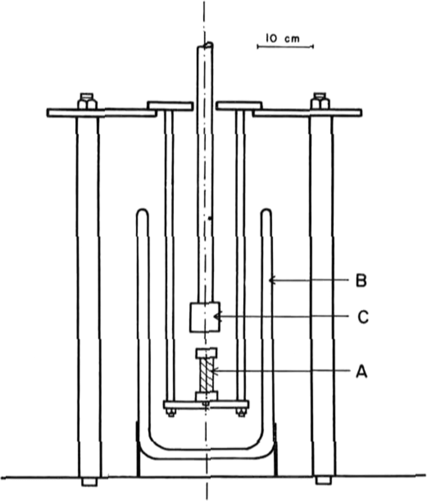
Fig. 1. Diagram of the jig that was designed for testing ice at 77 K using a model 1116 Instron machine.
The strain-rates used for the tests were between 10-5 and 10-3 s-1. The load was measured by a load cell installed in the Instron and the amount of deformation was deduced from the known strain-rate and the time.
The measured elastic deformation of the machine determined in a “dummy run” without a sample was subtracted from the deformation measured in a test and the result AL converted to strain ϵ by where L0 was the original specimen length. The load F was converted to stress σ using the equation
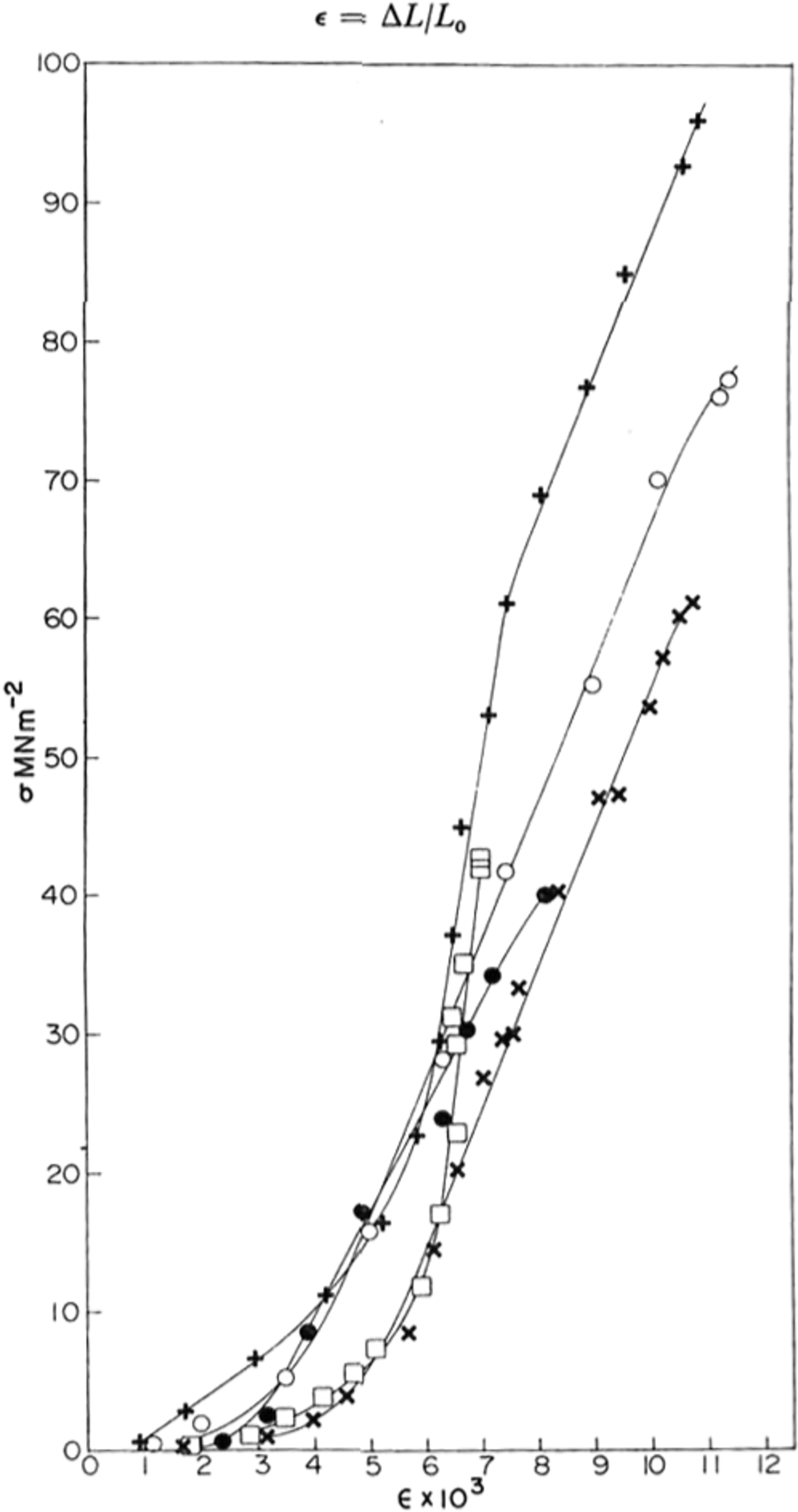
Fig. 2. Typical stress-strain crystal obtained for various samples of ice at yy K; ● polycrystaUine sample; X, ○ single crystals; + HF-doped single crystal; □ St Lawrence river ice.
where A0 was the original cross-sectional area of the specimen. For single crystals the load and strain were not resolved along the basal plane because basal slip did not occur at 77 K.
4. Results
(a) Stress–strain curves
Typical stress-strain curves obtained are shown in Figure 2. At first the stress increased slowly and then, at a strain of the order of 0.5%, it increased much more rapidly and linearly until an explosive fracture occurred.
The stress–strain curves shown in Figure 2 are similar in shape to those found in rocks at room temperature (Reference Hawkes and MellorHawkes and Mellor, 1970, p. 201) where there is an initial “stiffening” of the sample with increasing stress followed by a linear elastic region. At stresses approaching the strength of the ice (or rock), the slope of the stress-strain curve decreases until the unconfined compressive strength is reached. For such materials one cannot define an unambiguous Young’s modulus E since the stress-strain curve is non-linear. However, by measuring the slope of the curve we obtained the “tangent modulus” and this is shown for several samples as a function of stress in Figure 3. The maximum -4 2 value of the tangent modulus was 1 X 10⁻² MNm-3 for pure polycrystafline ice and 1.6 X 10⁻⁴ 4 MN m-2 2 for pure and HF-doped single crystals. These agree well with the value of E calculated at 77 K from Reference DantlDantl’s (1968) equations of 1.0 x 10⁻⁴ MN m.-1 and show that the linear region of the stress-strain curve is purely elastic. For the natural ice from the Rriver St Lawrence, the modulus was found to vary almost linearly with stress and a maximum value was not obtained.

Fig. 3. Tangent modulus for various samples plotted as a function of stress; O, ○, ×, +, □ pure single crystals; ●, ◊ HF-doped single crystals; Z, H St Lawrence riser ice, ■ pofycryslatlint ice.
(b) Failure
Upon failure the sample broke abruptly with an explosive noise. This explosion was probably not an inherent property of the ice but was due to an insufficiently “hard” testing machine. As Reference Hawkes and MellorHawkes and Mellor (1970) have pointed out, if the machine is insufficiently “hard”, elastic strain energy stored in the machine is released abruptly and uncontrollably when the test specimen reaches the lixnit of its resistance. The loading platens accelerate violently and the specimen is destroyed with explosive swiftness. If the machine is sufficiently “hard” the stress-strain curve dropsslowly and the specimen fails in a more controlled manner by the propagation of cracks.
Table I. Fracture Stress Data At 77 K

The mean fracture stresses σt that we observed are shown in Table I. There is quite a spread in values as indicated by the large standard deviation of a point. The pure ice single-crystals and the natural river ice polycrystals had the same mean strength while the laboratory grownpolycrystals were weaker. The mean value of fracture stress for the HF-doped crystals wasthe largest of all the ice types but this was because two samples had very high values. Within the standard deviation (±27) the HF-doped crystals were not significantly stronger. The theoretical strength ath of materials has been calculated by many workers (Reference FrenkelFrenkel, 1926) using various interatomic potentials, and its value is estimated to be in the range E/80 < σth < E\6π. The value of E for ice at 77 K extrapolated from Reference DantlDantl’s (1968) values of the elastic constants is 10 120 MN m−2 . If we use .E/40 = 253 MNm~2 as a reasonable estimate of the theoretical fracture strength in uniaxial compression, we obtain the values shown in Table II for a jam which have a mean value of 0.28 ± 0.11 .
Table II. Maximum Fracture Stress at 77 K

For both the pure and doped single crystals we found no dependence of fracture stress on strain-rate, within the range 10-2 to 10-3 s-1. In the pure, random polycrystals the fracture stress increased slightly with strain-rate, as shown in Figure 4 .

Fig. 4. Fracture stress plotted against strain-rate for polycrystailint ice at 77 K.
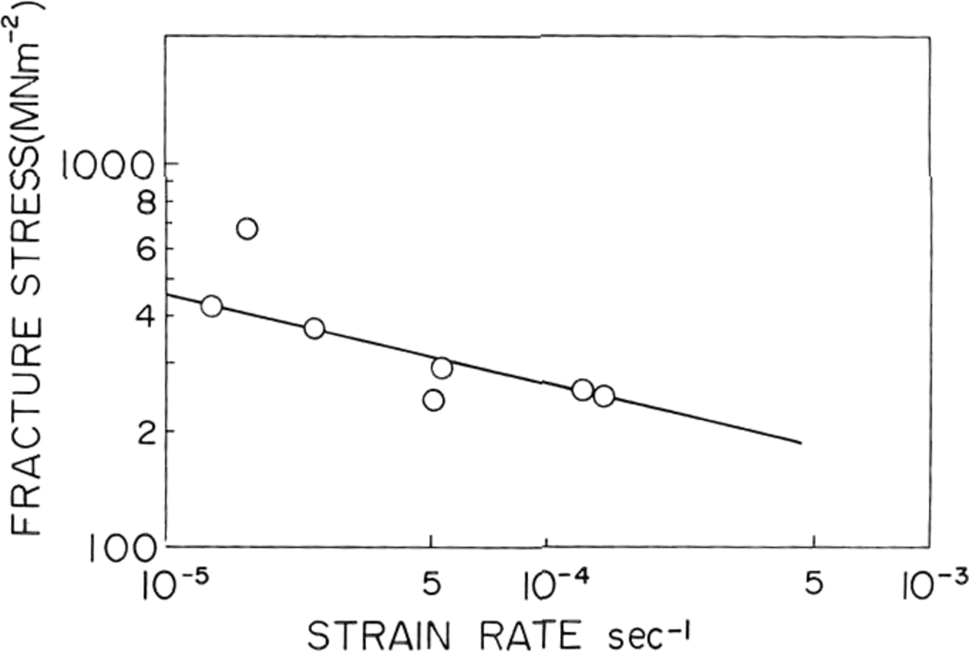
Fig. 5. Fracture stress platted against strain-rate/or St Lawrence river ice.
In natural ice the fracture strength was found to decrease with increasing strain-rate as shown in Figure 5. A similar result was obtained by Reference KorzhavinKorzhavin (1962) in fresh-water lake ice tested near its melting point. He fitted his data to an empirical relationship:
where die value of A was equal to 0.3 MN m-1 s-0.33 at –3°C and 0.24 MN m-1 s-0.33 at 3°C. The slope of the straight line on our log-log plot of of against ∈ shown in Figure 5 was –0.23 and therefore at for natural ice from St. Lawrence river was found to follow an equation,
where die value of A was 3.1 MN m-2 1 s-0.23.
The reason for this difference between the behaviour of the natural ice and the artificial ice is obscure but could be due to the dissolved impurities and the air bubbles entrapped during the formation of the natural ice.
(c) Cracks
The first crack appeared in the very early stages of deformation in the stress range 0.1-0.5 MN m-2, as indicated in Figure a, and was found to start at the top end cap and to extend from one end cap to another along a plane parallel to the axis. Figure 6 shows the first crack in a specimen which was taken out immediately after the crack formed. The formation of the first crack, which was accompanied by the emission of acoustic waves, was indicated by the clicking noise heard during deformation, and a corresponding drop in the load-elongation
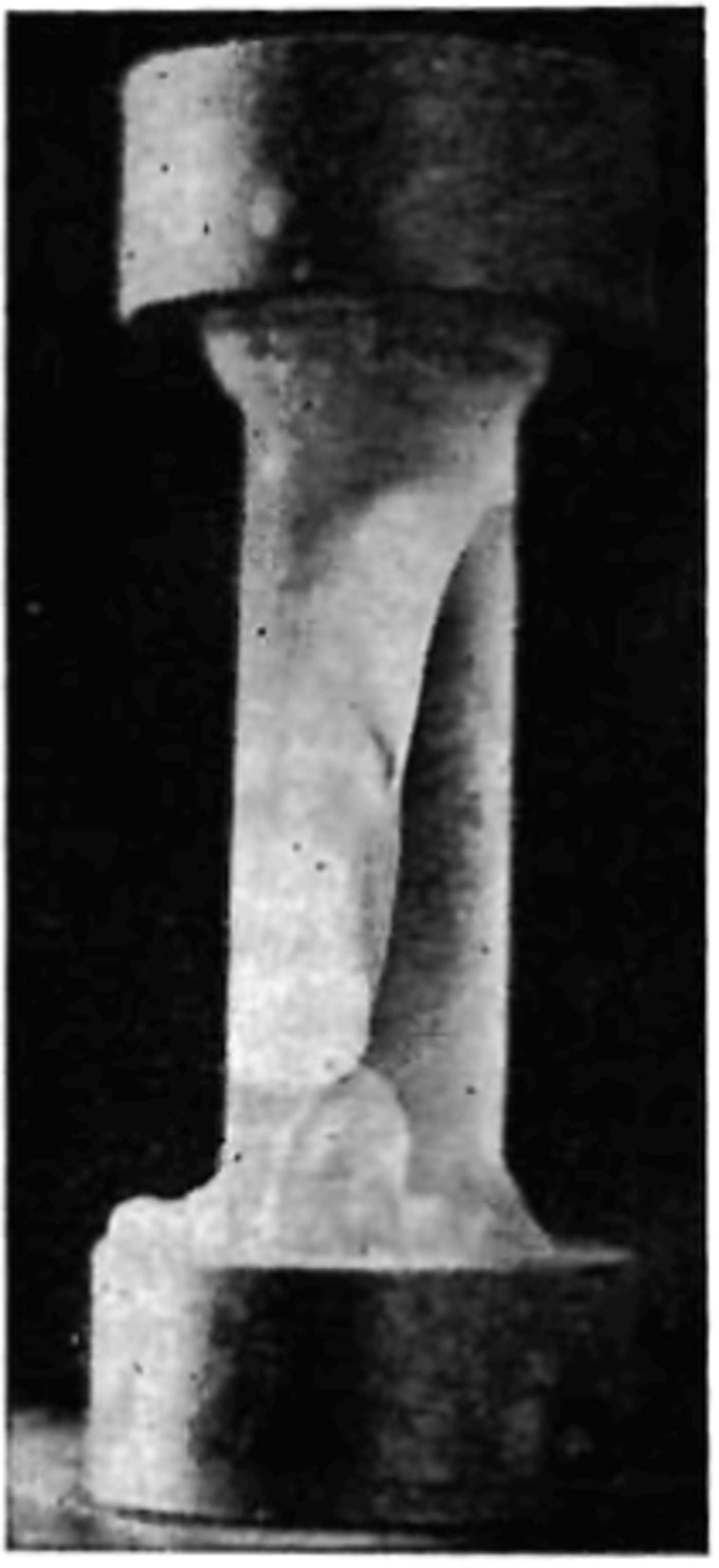
Fig. 6. The appearance of the first crack in a specimen.
curve. After the first crack was formed, the material was able to withstand a further increase in stress until failure. When the specimen neared failure, cracking activity increased considerably. The cracks did not follow any particular pattern or crystallographic plane. Figure 7 shows a specimen taken from the dewar after being loaded to a very high stress value and unloaded just prior to failure. At failure the specimen suddenly fractured with a loud explosion and disintegrated, forming a powder and leaving only two conical end fragments on the two end caps (Fig. 8).
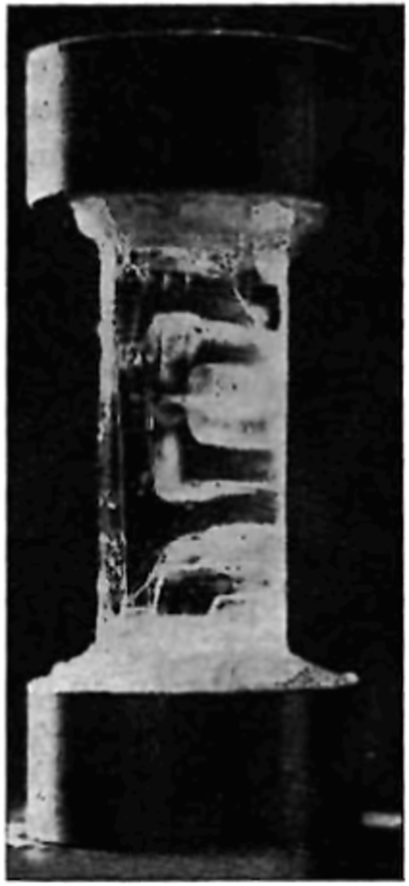
Fig. 7. A sample unleaded just prior to failure shaming the distribution of Cracks.
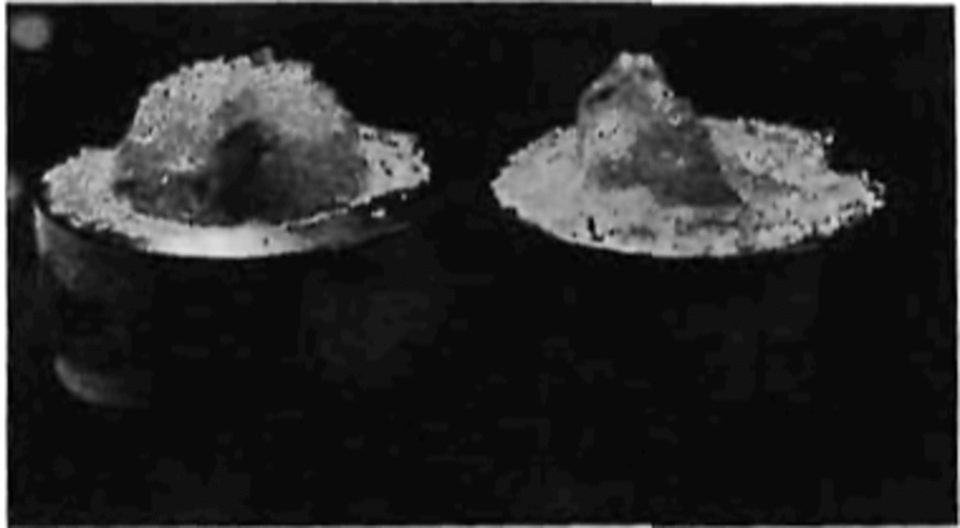
Fig. 8. Showing the end pieces of a sample after an explosive failure.
The modes of failure observed in ice were:
-
(a) axial cleavage, or vertical splitting, in which one or more major cracks split the sample along the loading direction; and,
-
(b) cataclasis, or general internal crumbling, by formation of multiple cracks in the direction of the applied load followed by specimen collapse, leaving conical end fragments together with long slivers along the periphery.
5. Discussion
The similarity between the shape of the stress-strain curves for ice at 77 K and rocks at room temperature is striking, and their homologous temperatures are similar, 0.2-0.31,.... The explanation of the initial curvature of the stress-strain curves for rocks is attributed to progressive closure of cracks and pores under stress (Reference BraceBrace, 1965; Reference WalshWalsh, 1965[a], Reference Walsh[b], Reference Walsh[c]; Reference Walsh and BraceWalsh and Brace 1966[a], Reference Walsh and Brace[b]).
In our ice samples there were no pre-existing cracks or pores, as far as we could tell. The polycrystalline ice had some minute air bubbles but the single crystals did not, yet there was no significant difference between the initial curved parts of the stress-strain curves for the single crystals and polycrystals. Thus, the initial curvature is not due to closure of entrapped air bubbles or to grain-boundary slip. However, it is possible that immersion of the sample in liquid nitrogen caused the opening up of microcracks, although none were visible to the eye, and that it is these cracks which are closing up under the initial stress. The first cracks large enough to be visible to the naked eye were formed in the initial non-linear part of the stress-strain curve and so it is possible that at even lower stresses microcracks were being formed and then healed.
The linear behaviour at higher stresses is taken, in rocks, to represent elastic straining of the constituent grains and we believe the same to be true for ice because the tangent modulus in this region agrees well with the elastic modulus value obtained from sound-velocity experiments. The decrease in the slope of the stress-strain curve at stresses approaching the uniaxial strength of the ice, or of rock, is due to the formation of many cracks which eventually cause the specimen to collapse. The fact that ice behaves in the same way as rocks at 0.2 Tm is an encouragement to geologists who wish to model the behaviour of rocks at high temperatures, as found in the Earth’s mantle, by using the results of high-temperature ice deformation studies, most of which have been made at T > 0.9Tm .
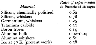
As we have shown, the fracture stresses at 77 K were of the order of 0.3σth. For comparison with other materials, Table III shows values of fracture stresses quoted by Reference StokesStokes (1972). Our present ice values are as high as most of the values in Table III, with the exception of alumina and silicon “whiskers” (which presumably have very low or zero dislocation densities) and chemically polished silicon.
Table III. Comparison of the Strength of Ice
HF doping of single crystals had almost no effect on the stress-strain curves at 77 K. At higher temperatures, around 200 K, HF doping softens single crystals of ice markedly (Reference Jones and GlenJones and Glen, 1969[a]), by enabling dislocations to move faster. At 77 K, thermal energy is not sufficient to activate motion of dislocations, although they could be stress-activated. Hence it is not surprising that there is no effect of the HF doping. One of the HF-doped samples showed the largest fracture stress of all the specimens but, because of the variation in the fracture-stress results, this is not statistically significant.
At high temperatures (260 K) ice deforms plastically at these strain-rates after an initial elastic region and a yield drop. At 77 K, ice is clearly brittle at these strain-rates. In principle, however, ice would probably be ductile at 77 K at sufficiently low strain-l rates, although in practice these strain-rates are unobtainable, being of the order of 10-14 a-1. . Strictly the terms “brittle” and “ductile” should be used to characterize the process rather than the material (Reference BieniawskiBieniawski, 1967). Reference HandinHandin (1966) has suggested that descriptive terms might be defined on the basis of the total strain which occurs before the peak stress is reached. These are:

On this basis, ice at 77 K is “brittle” to “very brittle".
The stress required for the onset of brittle cleavage can be calculated from the criterion for transition from ductile to brittle fracture given by Reference PetchPetch (1968).
where γ is the surface energy, d is the grain diameter, μ is the shear modulus, and kt is a constant governing the grain-size dependence of fracture stress
where σ0 is a constant related to the frictional force acting on the moving dislocations. Equation (1) shows that for a single crystal the stress for the onset of cleavage could be very small
compared to that for a polycrystal. Since ice has only one primary slip system we can apply the mechanism proposed by Reference StrohStroh (1957). According to his model, kt is given by

where b is the Burger’s vector of the relevant dislocation and v is Poisson’s ratio. Using the values μ = 3.77 × 10³ MN m-2, b = 4.5 × 10⁻¹⁰ m and v = 0.34 we obtain for ice at 77 K
Using this value of kt in Equation (1), together with d = 20 mm (the diameter of a specimen) and γ = 10-7 MN m-1 suggested by Gold (unpublished), we obtain
Our experimentally observed values of stress for the formation of the first cleavage cracks were in the range 0.1-0.5 MN m-2, which is in good agreement with the above theoretical value for the onset of brittle cleavage.
There is little previous work on the brittle behaviour of ice with which to compare our results, and none at low temperatures. Reference GoldGold (1972) has made a comprehensive study of cracks in ice and Carter (unpublished) and R. O. Ramseier (personal communication) have measured failure stresses at temperatures above –400 C Their data is shown in Figure 9 together with ours at 77 K. Because of the large temperature difference between the measurements, and the scatter in the data, it is difficult to draw comparisons but there is a definite trend towards higher stresses at lower temperatures.
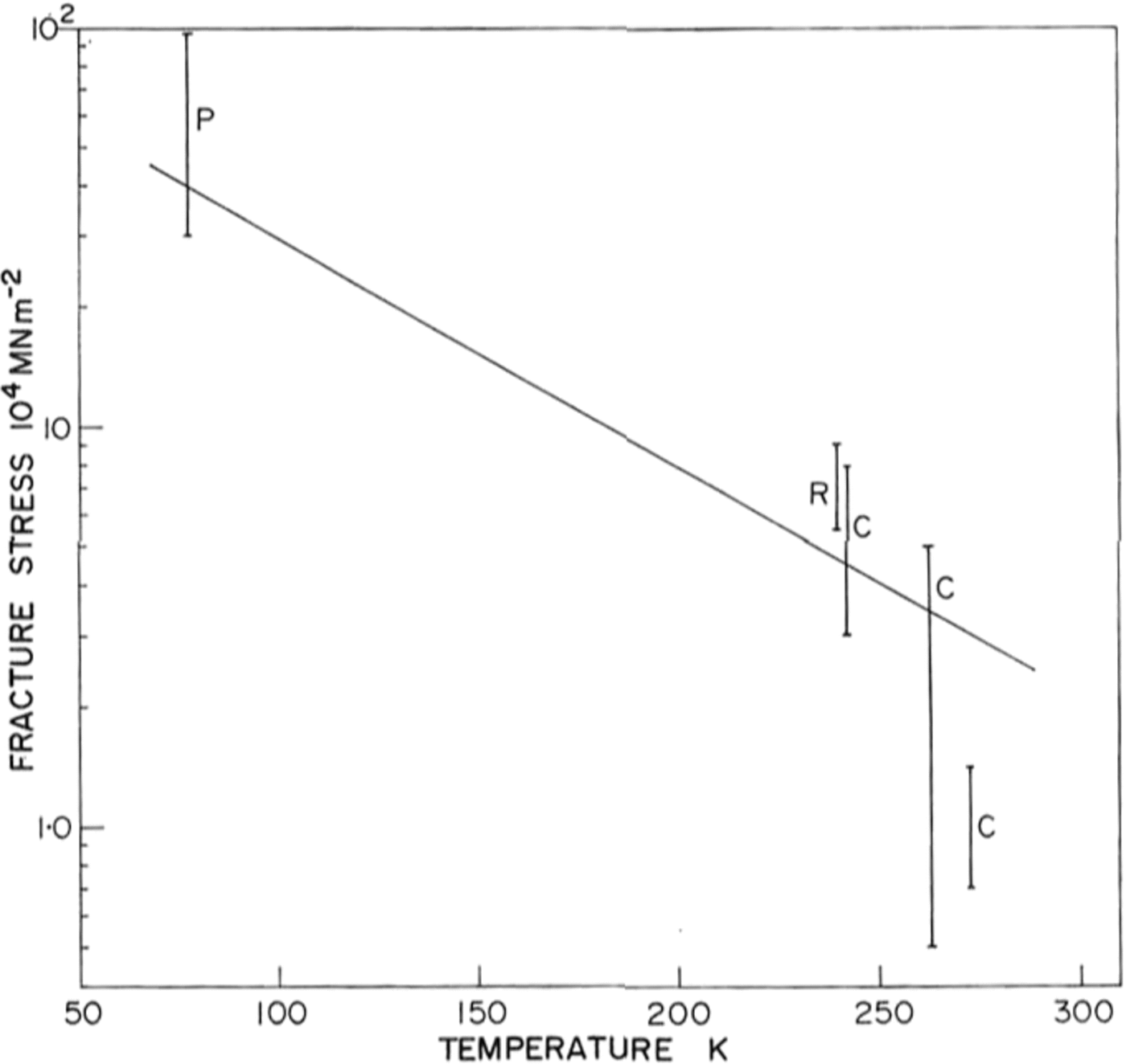
Fig. 9. Ice fracture stress as a function of temperature P, present work; R, personal communication from 1 R. 0. Ramseier; C, Carter (unpublished).
6. Conclusions
At 77 K, ice is normally brittle and behaves in a similar manner to rocks at 0.2-0.Tm. The failure stresses are high and approach 0.3 of the theoretical strength. HF doping has no effect at this temperature.
Acknowledgement
We are grateful to Mr R. O. Ramseier for providing both the river-ice samples and some unpublished fracture data.


