


Introduction
Transmission electron microscopy (TEM) today is the essential tool for materials characterization when site-specific chemical or structural detail is required.Reference Williams and Carter1,Reference Carter and Williams2 If you want to know the chemistry at a crack tip or the uniformity of a coating on a nanoparticle, then you must use TEM or scanning transmission electron microscopy (STEM). (S)TEM can be used to characterize all materials, from the hardest ceramics and metals to the softest polymers and the smallest nanoparticles. It can also be applied to living material, almost invariably when it is no longer living. By “living,” we mean human, animal, and vegetable, and by “no longer” we could mean after recent surgery or after mummificationReference Pabst and Hofer3 or fossilization.Reference Javaux, Knoll and Walter4
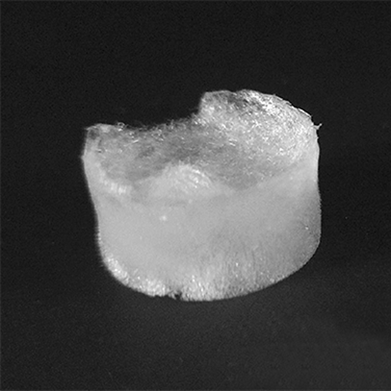
The TEM research community has tended to separate into three groups—the physical scientists, the biologists, and the instrumentalists. Modeling and software specialists tend to segregate into these same groups. Recent developments in TEM and STEM have begun to see a convergence of these different fields; the use of cryogenic techniques is one aspect where these groups have more in common than differences. The commonalities can be the instruments, the many ways we now have to prepare specimens for the TEM, or even the ways that we acquire, manipulate, and analyze experimental data. The new capabilities can be appreciated by comparing the macroscopic appearance of cryotemplated and pressurized gas expansion cellulose nanocrystal aerogels in dry and wet states, as shown in Figure 1. The difference is clear in the macroscopic image but cryo-TEM will show the full picture.Reference Osorio, Seifried, Moquin, Grandfield and Cranston5
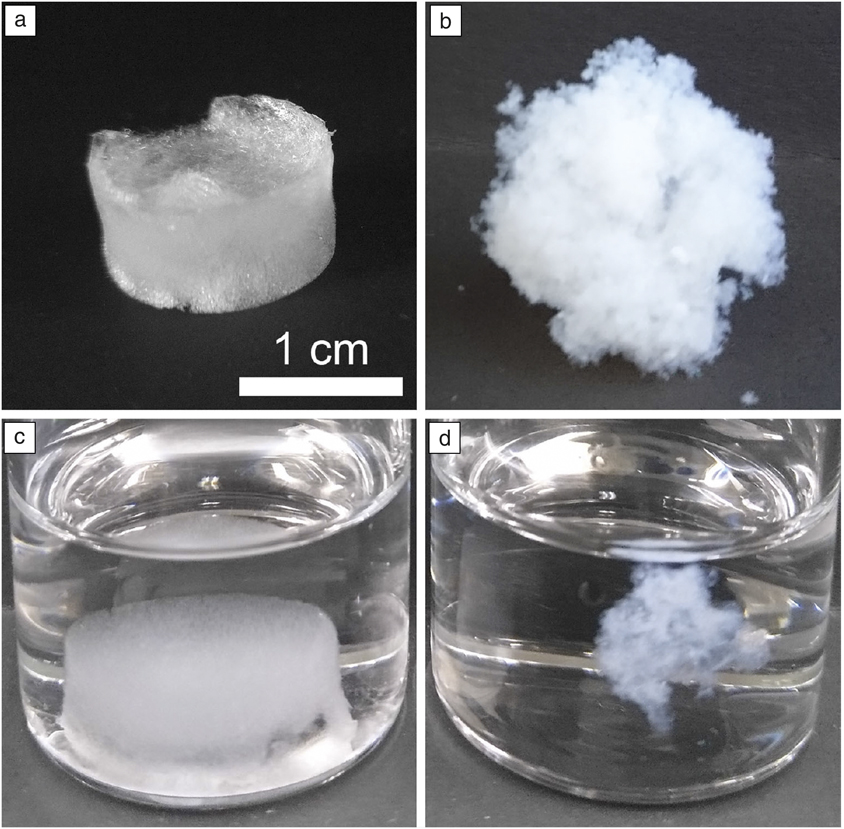
Figure 1. Comparison of the macroscopic appearance of cryotemplated and pressurized gas expansion cellulose nanocrystal aerogels in (a, b) dry and (c, d) wet states. The scale bar applies to all images. The difference is clear in (c, d) the macroscopic image, but (a, b) cryogenic transmission electron microscopy will show the full picture.Reference Osorio, Seifried, Moquin, Grandfield and Cranston5
Method of the year and a Nobel Prize
In 2017, the Nobel Prize in chemistry was awarded to J. Dubochet, J. Frank, and R. Henderson “for developing cryo-electron microscopy for the high-resolution structure determination of biomolecules in solution.”6 In this application of cryogenic (cryo)-TEM, wherein proteins are imaged, the temperature of the sample must be maintained at liquid-nitrogen temperatures or below. While the low temperature not only confers radiation damage protection to samples, it also is necessary to maintain the sample in the vitreous state where proteins adopt near-native conformations. Modern automated cryo-TEMs are designed specifically to operate at liquid-nitrogen temperature.
In awarding the Nobel Prize, the Royal Swedish Academy of Sciences explained that cryo-EM has “taken biochemistry into a new era.”7 (Microscopists were initially so excited to get some recognition that they forgot about the missing T, but we will include it.) The journal Nature Methods had actually named “single-particle cryo-electron microscopy (cryo-EM)” the “Method of the Year for 2015,” stating that it meant the end of “blob-ology.”8 The announcement was accompanied by a historical perspective,Reference Nogales9 which recognized the pioneering work by Taylor and Glaeser,Reference Taylor and Glaeser10 and by a commentary asking “how good can cryo-EM become?”Reference Glaeser11
Today’s success of cryo-TEM builds on the independent work of the three Nobel Laureates, but three much more recent developments were essential before its potential could be realized. We now have a new class of direct electron detector cameras, much more stable specimen stages, and for the highest resolution, an aberration-corrected objective lens. The direct electron detector camera makes every electron count by counting every electron. Very stable stages are now available because of the attention being paid to mechanical and thermal stability and such small amounts of drift can be corrected on the fly. Aberration-corrected microscopes are now available from several manufacturers thanks to developments by Rose, Haider, Urban, and Krivanek.Reference Haider, Uhlemann, Schwan, Rose, Kabius and Urban12,Reference Krivanek, Dellby and Lupini13 While aberration correction has found limited application in cryo-TEM for structural biology, at least to date, the ultrastable electron optics necessary to support aberration correction are a key contributor to the success of cryo-TEM. Cryo-TEM is now the method of choice for characterization in structural biology, in many cases replacing x-ray diffraction, and the plethora of newly installed instruments worldwide is generating data faster than can be fully analyzed.
The rest of materials
We were then led to ask “what is the impact of cryo-TEM on materials research where the materials are not biological?” This question is the subject of this collected set of articles in this issue of MRS Bulletin. We lead off with the Williams et al. articleReference Williams, McComb and Subramanian14 discussing the instrumentation since it is the development of instruments that has made this revolution possible for biochemists. The advantages and disadvantages of TEM and STEM for biological and physical sciences research are reviewed and detector technology, both current and emerging, are discussed.
We examine the two types of material that are most likely to be impacted by cryo-TEM. These are, of course, materials that have much in common with the biological materials, namely, soft materials (see the Watt et al. article)Reference Watt, Huber and Stewart15 and very soft materials (see the Zachman et al. article).Reference Zachman, de Jonge, Fischer, Jungjohann and Perea16 The latter, liquids, are much too “soft,” so we need to use cryo-techniques to make them stay where we put them in the microscope. In both cases, it is hoped that freezing the specimen will also stop, or at least decrease, changes that might occur over time, especially when the specimen is subjected to the electron beam. But changes will inevitably occur as they do in all TEM studies, so we include a critical consideration of what might happen when the electron beam passes through the specimen (see the Russo et al. article).Reference Russo and Egerton17
In their article in this issue, Nannenga et al.Reference Nannenga and Gonen18 address another of the strengths of TEM; the TEM is an analytical machine that not only produces images, but also provides diffraction dataReference Taylor and Glaeser10 and information on the chemistry, both composition and bonding. A contribution by Minor et al.Reference Minor, Denes and Muller19 considers the impact that cryo-EM could have in the field of quantum materials where investigation and understanding of low-temperature phenomena is critical to future developments.
It might be anticipated that the greatest impact for cryo-TEM in materials research would be in the field of polymer science or possibly in the study of composite materials that include polymers and materials that, like biological samples, are wet in real life, or may include a wet component.
Making specimens of composite materials has always been a challenge, which is why bottom-up specimen preparation is always preferred over top-down; the interest in nanoparticles has been a boon for TEM because we already have the specimen thin enough for electron transmission. We can now link cryogenic scanning electron microscopy to cryo-TEM, making TEM of specimens, such as those shown in Figure 2,Reference Preller, Runge, Zellmer, Menzel, Saein, Peters, Raatz, Tiersch, Koetz and Garnweitner20 possible.
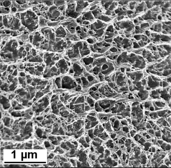
Figure 2. Cryogenic scanning electron microscope image of the gel network formed by poly(vinyl alcohol) cross-linked by borax. This hydrogel is used in soft robotics applications.Reference Preller, Runge, Zellmer, Menzel, Saein, Peters, Raatz, Tiersch, Koetz and Garnweitner20
Liquid films on small objects,Reference Du, Chen, Meckes, Kluender, Xie, Dravid and Mirkin21 or even in thin layers,Reference Carter and Williams22 are technologically extremely important. But if you have a “bulk” sample and need to thin it, then you need to know where to go to make that specimen. Once you have the specimen, which microscope should you use? The first choice (the one you have immediate access to) may not be the best choice. Fortunately, user facilities are developing across the United States and internationally, where one can collaborate to use the optimum TEM once you know what that is. The most popular collaborator for any TEM expert is a researcher who has already prepared the specimen, and the most popular collaborator for the researcher with the specimen is the TEM expert who will to examine it.
The article by Williams et al.Reference Williams, McComb and Subramanian14 describes some of the instruments available and considers how best to utilize them for different types of experiment. Not all studies require an aberration-corrected instrument. 100 kV is sometimes better than 300 kV, depending on the material and possibly the detector. However, the flexibility to use a range of detectors and methods often comes at the cost of instrument stability.
If your radiation-sensitive sample forms nanocrystals
It is now possible to utilize a new methodology called micro-electron diffraction (MicroED) to determine the three-dimensional structure of radiation-sensitive samples such as proteins, small molecules, or nanomaterials from nanocrystals. While diffraction methods in TEM are common when applied to nanomaterials, this is a new variation of cryo-TEM.Reference Nannenga and Gonen23 In MicroED, the cryo-TEM is operated in diffraction mode, and crystals are often on the order of 1 µm in size. For protein structure determination, crystals are often a billionth of the volume typically used for x-ray crystallography. The TEM used is essentially the same as traditional cryo-TEMs, aside from a few minor modifications, and the addition of a specialized complementary metal oxide semiconductor (CMOS)-based detector optimized for continuous acquisition of extremely low-dose diffraction-pattern collection. Continuous-rotation diffraction data sets are processed using existing x-ray crystallographic software packages. Given the minor modification needed to enable MicroED, many existing cryo-TEMs can be retrofitted to perform this technique, and it is expected that there will be dramatic growth in this research methodology in the very near future. The article by Nannenga and GonenReference Nannenga and Gonen18 in this issue discusses MicroED.
If it’s not bio
The issue includes two articles on the materials most obviously benefiting from cryo-TEM. We consider cryo-TEM of soft materialsReference Watt, Huber and Stewart15 and materials that would contain liquidsReference Zachman, de Jonge, Fischer, Jungjohann and Perea16 if they were at room temperature. In both cases, the materials have much in common with biomaterials—the aim of cryo-temperatures is to stop, or at least minimize, any movement or changes in the specimen, so the cooling (freezing) needs to occur as quickly as possible. When water is present, cooling has to be so fast that the water cannot crystallize—it must remain in the vitreous state (e.g., see Figure 3). We also want no expansion to occur since this might distort the specimen. Similarly, the formation of ice crystals would add confusion to the interpretation in addition to changing the specimen.

Figure 3. Water-soluble magnetite (Fe3O4) nanoparticles: cryo-TEM revealed that these higher order assemblies were present in solution. Conventional TEM could not be used to confirm these observations due to drying artifacts. The diameter of the particles is in the range of 5–25 nm. Courtesy: J. Watt and D.L. Huber.
Clearly then, we do not want the specimen to change before we look at it in the TEM, but we also do not want it to change when we examine it. This brings us to consider how the electron beam might change the specimen, and what voltage to use. Basically, the electron beam will change the specimen; the uncertainty is only how fast it will change or, in other words, how long we have to make observations. It should be remembered that high-voltage TEMs were in fact used extensively in the 1960s to simulate damage occurring in nuclear reactors. The changes can be caused either by direct impact of electrons (energy and momentum transfer) or by interaction between charged particles—the electrons in the beam and atomic nuclei in the specimen. In the first case, it is worse if the accelerating voltage is high, while in the latter, if the voltage is low. These differences mean that the choice of TEM may not be immediately obvious for a particular specimen. Only recently has quantitative analysis of beam damage started to become a reality for organic films.Reference Leijten, Keizer, de With and Friedrich24 The Zachman et al. article on solid–liquid interfacesReference Zachman, de Jonge, Fischer, Jungjohann and Perea16 has many implications—the liquid is not necessarily water. The technique has enormous application to energy materials, such as batteries, and fields, such as corrosion.Reference Zachman, Tu, Choudhury, Archer and Kourkoutis25
Our penultimate topic emphasizes why the TEM is unique and aims to encourage users to become more familiar with the other capabilities of the instrument. Even if you know that your specimen only contains carbon, oxygen, and hydrogen, the TEM can give you information on the bonding; it may also tell you about contamination that you did not know was present. The TEM gives two principal approaches to chemical analysis, either x-ray energy-dispersive spectroscopy (XEDS) or electron energy-loss spectroscopy (EELS); if you are making measurements, you would use spectrometry instead. Traditionally, XEDS has favored heavy elements and EELS has favored light elements, but improved detectors and software have begun to blur these distinctions. Similarly, diffraction used to be just for TEM, not STEM, but that too is changing, again partly because of new detectors (in this case, the direct-electron-detector cameras) and partly because of improving software.Reference Earl, Falconieri, Milne and Subramaniam26 When we say software, we are not just thinking about interpreting the spectrum or diffraction pattern; today, we may be collecting so much data that no person will ever have the time to look at it all. This raises other questions such as does your institution really have the capability to store data as you claimed in your data plan and would anyone else ever have time to access it if they did. Here, the non-biomaterials researchers have exactly the same challenges as the biological and biochemical cryo-TEM users.
There has long been great interest in using cryo-TEM to study materials that have different properties at cryogenic temperatures. For example, the late A. Tonomura and his colleagues performed classic experiments verifying the Aharonov–Bohm effect, observing the movement of magnetic flux lines (flux vortices) in niobium at temperatures as low as 4.2 K, and especially watching changes occur as the specimen warmed from 4.5 K and 15 K.Reference Tonomura27 Such cryogenic work requires a stage that is cooled by liquid helium. These experiments are difficult because of the temperature and the need for a Lorentz lens, but the information is not achievable by any other means.Reference Berruto, Madan, Murooka, Vanacore, Pomarico, Rajeswari, Lamb, Huang, Kruchkov, Togawa, LaGrange, McGrouther, Ronnow and Carbone28 Unfortunately, TEM using liquid-helium quickly becomes expensive. What physics might be revealed by an ultrastable cryo-TEM operating at liquid helium temperatures?Reference Minor, Denes and Muller19 Arguably, the greatest impact would be in driving quantum materials research that has become the focus of physics and materials communities across the world.
It won’t cool off
We can draw a few conclusions regarding cryo-TEM and what it can do for non-biomaterials science. The microscopes are essentially the same—for both groups, the TEM is an electron-optics column with an electron source and everything controlled by computers. No one ever “sees” the sample—we all form images of the specimen and then interpret the images. Both groups are interested in obtaining information about all three dimensions (not just a two-dimensional projection) and will want to know the chemistry of the specimen. Using new direct-electron-detector cameras, both groups are faced with storing, processing, and retrieving more data in a week than what previous generations of TEM users produced in a lifetime. In science and life, most things happen at interfaces. Most materials we use are composite materials, ranging from electronic devices to reinforced concrete. For medical implants, the contact to the body is critical. Targeted drug delivery uses carrier particles to transport the drug to the target.Reference Win and Feng29 These examples emphasize the developing links between bio- and non-biomaterials. So it is not just what can we learn from the success of bio-cryo-TEM, but how can we improve the links between different fields of cryo-TEM.
Acknowledgments
C.B.C. acknowledges support from the National Science Foundation Award Nos. 1820565 and DMR-1710468. He conducts his research in CINT, which is an Office of Science User Facility operated for the US Department of Energy (DOE). Sandia National Laboratories is managed and operated by National Technology and Engineering Solutions of Sandia, LLC, a wholly owned subsidiary of Honeywell International, Inc., for the DOE’s NNSA Contract No. DE-NA-0003525. D.W.M. is supported by the State of Ohio Third Frontier Program as an Ohio Research Scholar.
David William McComb is a professor of materials science and engineering and director of the Center for Electron Microscopy and Analysis at The Ohio State University. He received his BS degree in chemistry in 1987 from the University of Glasgow, Scotland, and his PhD degree in physics in 1990 from the University of Cambridge, UK. His research focuses on the development and application of scanning transmission electron microscopy and electron energy-loss spectroscopy as a subnanometer-scale probe of chemistry, structure, and bonding. He is a Fellow of the Royal Society of Chemistry, the Institute of Materials, and the Microscopy Society of America. McComb can be reached by email at mccomb.29@osu.edu.
Jeff Lengyel is the principal scientist for Electron Microscopy Life Sciences for Thermo Fisher Scientific, formerly FEI Company. He received his PhD degree in biochemistry in 2007 from the University of Cambridge, UK, and his BS degree in biochemistry from the University of California, Davis, in 2001. His previous roles include product marketing manager for structural biology, on-site team lead for the FEI/NIH Living Lab for Structural Biology, and Senior Titan Krios Applications Specialist. He completed doctoral research on the pyruvate dehydrogenase using a combination of CryoEM and biophysical techniques. Lengyel can be reached by email at jeffrey.lengyel@thermofisher.com.
C. Barry Carter is a Center for Integrated Nanotechnologies Distinguished Affiliate Scientist at Sandia National Laboratories, a visiting academic at The University of Manchester, UK, and a research professor at the University of Connecticut. He received his DPhil degree in 1976 from the University of Oxford, UK, and his ScD degree in 2005 from the University of Cambridge. He was previously on the faculty of Cornell University from 1979 to 1991, and the University of Minnesota from 1991 to 2007. Carter co-authored textbooks on transmission electron microscopy and ceramic materials. He is a Fellow of the Materials Research Society, the American Association for the Advancement of Science, The American Ceramic Society, the Royal Microscopical Society, Microscopy Society of America, and the Microanalysis Society. His current research focuses on phase-change materials, crystal dislocations, and reactions between Li/Na and layer materials. Carter can be reached by email at cbarrycarter@gmail.com.


