


I. INTRODUCTION
Resistance to crack propagation is undoubtedly one of the most important properties of structural materials. However, our current mechanistic understanding of the energy-dissipation processes involved on the various scales and of their interplay is not sufficiently advanced to predict the fracture behavior of materials ab initio.Reference Hutchinson and Evans1,Reference Needleman and Van der Giessen2 As fracture is ultimately caused by the breaking of atomic bonds,Reference Bitzek, Kermode and Gumbsch3 there is a high demand for atomistically informed fracture criteria. An overview of ongoing attempts to realize them in hierarchical and concurrent schemes can be found, e.g., in Refs. Reference Shiari and Miller4 and Reference Rabczuk5. Here we propose a hierarchical scheme that meets two common challenges: to extract information on the atomic scale in an efficient manner and to coarse-grain this information to obtain practical and meaningful failure criteria for a finite element (FE) implementation on the mesoscale. Our approach is demonstrated by making use of cohesive zones (CZs), but is not limited to this model.
A so-called cohesive zone model is a seemingly natural way to incorporate atomistic information in a continuum model of fracture. In a traditional CZ model, the fracture process zone (i.e., the region in which nonlinear processes occur) ahead of the crack tip is represented by cohesive surfaces (respectively a narrow band of vanishing thickness) which experience cohesive tractions described by a constitutive law, the so-called traction-separation (TS) law. Crack growth occurs when the separation at the tail of the CZ, i.e., at the physical crack tip, reaches a critical value at which the cohesive traction vanishes. The strip yield model of Dugdale,Reference Dugdale6 which was originally proposed for estimating the size of the plastic zone around a crack tip, is regarded as one of the first CZ-type models. BarenblattReference Barenblatt7 also proposed a cohesive fracture concept with the aim to eliminate the crack tip stress singularity in classical linear elastic fracture mechanics (LEFM). For fracture of perfectly brittle materials, the descriptions by LEFM and the CZ model approach are equivalent if the material behavior in the zone around the crack tip is determined by the stress-intensity (K) field and if the cohesive energy density is identical to the critical energy release rate.Reference Rice and Liebowitz8 The first condition is met when the fracture process zone is smaller than the K-dominated zone (the region with a significant gradient in the stress), which is the case in brittle materials.Reference Singh, Kermode, De Vita and Zimmerman9,Reference Shimada, Ouchi, Chihara and Kitamura10
A crucial point to consider in practical applications within a finite element method (FEM) implementation is that CZ-based numerical techniques require cracks to propagate along the element boundaries. Therefore, an inherent nonvanishing amount of mesh dependency arises, which can become dominant for three-dimensional simulations in a homogeneous material.Reference Zhou and Molinari11 For instance, no converged solutions from the simulation of progressive delamination were obtained above a critical mesh size.Reference Turon, Dávila, Camanho and Costa12 As a general rule, Hillerborg et al.Reference Hillerborg, Modéer and Petersson13 suggested a maximum characteristic length  ${l_{{\rm{coh}}}} \approx {{{G_{\rm{c}}}} / {\sigma _{\rm{c}}^2}}$ for the CZ under mode I loading, based on the cohesive energy G c and the critical stress to initiate crack advance σc. This characteristic length is always smaller than the radius of the K-dominated zone at critical loading, but also larger than the fracture process zone. In our approach, we couple the mesh size to the critical stress, which is the object of a scaling procedure explained in Sec. III. Furthermore, we do not only treat the fracture process zone as a CZ, but sample the complete K-dominated region on the cleavage plane with cohesive elements. This way, we obtain mesh-independent results for the fracture toughness under mode I loading.
In principle, the TS law can capture the physics of deformation and failure on the microscale, provided its shape is chosen carefully and that it includes important parameters such as maximum strength, work of separation, and critical displacement.Reference Chandra, Li, Shet and Ghonem14 Within the hierarchical modeling approaches, there are basically two philosophies about how to incorporate this information in TS laws, which differ in the way in which dissipative processes enter the modeling framework.
TS laws derived from atomistic simulations of homogeneous deformation of a single crystal, a bicrystal, or even model sections of polycrystalline microstructures can produce a stress–strain curve which reflects both elastic and dissipative processes during fracture.Reference Spearot, Jacob and McDowell15–Reference Barrows, Dingreville and Spearot21 However, dissipating the energy which is released during crack initiation and growth can be severely constrained in microstructuresReference Kumar and Curtin22 so that the fracture toughness becomes dependent on length scale and geometry. This means that the TS law would have to be adapted for each specific microstructure. Instead, we want to promote an approach in which the process of material separation by breaking of atomic bonds is separated from energy dissipative processes, such as plastic deformation accommodated by generation and motion of dislocations. The description of bond breaking within the CZ can be combined with different levels of description of the plastic deformation in the material adjacent to the CZ. On the smallest scale, plasticity is described based on discrete dislocation dynamics models in twoReference Cleveringa, Van der Giessen and Needleman23–Reference Broedling, Hartmaier and Gao25 or three dimensions.Reference Déprés, Prasad Reddy, Robertson and Fivel26 Further developments include the formulation of the virtual internal bond model of cohesive fracture and its application to nanomaterials.Reference Zhang, Klein, Huang, Gao and Wu27,Reference Ji and Gao28
Following the failure criterion by Griffith, the TS law for the bond-breaking process will have to capture the work of separation of the material, but to predict reliably the trends in cohesive behavior, the strength of the bonds is required as well.Reference Tahir, Janisch and Hartmaier29 The strength of interatomic bonds is reflected in the theoretical strength of a material, which can be determined via ab initio density functional theory (DFT) calculations for single crystalsReference Ogata, Li and Yip30,Reference Černý and Pokluda31 as well as interfaces with and without impurities.Reference Šob, Friák, Legut, Fiala and Vitek32–Reference Gibson and Schuh34 However, this procedure assumes homogeneous expansion perpendicular to, or cleavage along, an infinite crystallographic plane. During such a process, all bonds across the anticipated cleavage plane are elongated by the same amount and rupture at the same time. By contrast, individual pairs of atoms across the cleavage plane in the vicinity of the crack tip experience different environments, due to the gradient of the elastic displacement ahead of a crack tip, as shown in Fig. 1. Thus, the equivalence of the stresses obtained from such a rigid body separation (RBS)-type calculation with the critical stress needed to advance a crack tip still has to be demonstrated. This is one of the aims of the present paper (see Sec. II).
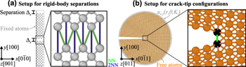
FIG. 1. Simulation setups for rigid-body separations (a) and crack-tip configurations (b). Note that not all interacting nearest-neighbor (NN) pairs (green; color online) are shown here due to the two-dimensional visualization. In fact the number of interacting NN pairs is twice the number of interacting 2nd NN pairs.
Embedding an atomistics-based TS law into a fracture model via CZs in a FE scheme has also practical issues because the theoretical strength is of the order of GPa and the critical separation is of the order of Å.Reference Tahir, Janisch and Hartmaier35 The stresses on the order of the theoretical strength occur very locally in the extreme stress gradient in front of the crack tip, i.e., usually within the first few layers of atoms. In contrast to this, any continuum modeling is based on describing average stresses in some finite volume such that typical stresses occurring in FE models are much smaller. Therefore, Serebrinsky et al. first used a scaling relation for TS lawsReference Serebrinsky, Carter and Ortiz36 derived from the results of ab initio calculations based on the concepts introduced in Refs. Reference Nguyen and Ortiz37 and Reference Hayes, Ortiz and Carter38. It assumes that the critical stress needed to separate two half crystals depends on the amount of elastic energy that is stored and released from the material next to the cleavage plane, which in turn scales with the system size. This can easily be observed in atomistic supercell calculations in which two half crystals are shifted and the atomic positions are relaxed afterwards. If the theoretical strength is simply identified with the maximum of the derivative of the energy–displacement curve, it decreases with an increasing number of planes parallel to the cleavage plane.Reference Nguyen and Ortiz37 However, the amount of energy that localizes and is subsequently released during the fracture process is in fact finite,Reference Elsner and Müller39 and the seemingly size-dependent fracture stress can be normalized to obtain the unique strength of the material.Reference Enrique and Van der Ven40 Thus, a scaling approach via the elastic energy is practical, but not well justified, and a physically meaningful coarse-graining scheme providing an unambiguous connection between the macroscopic and microscopic stresses is still needed.
With the work at hand, we want to promote tensile tests carried out by RBSs and translations in combination with a scaling approach based on pairwise forces. RBS schemes can be used to characterize single crystals and grain boundaries on the same footing,Reference Janisch, Ahmed and Hartmaier41 provide a three-dimensional description of single crystalReference Sun, Beltz and Rice42 and grain boundary separation,Reference Pang, Janisch and Hartmaier43 and can be extended to include impurity effects.Reference Tahir, Janisch and Hartmaier35 Most importantly, the derived critical stresses are size independent without any normalization. Our scaling approach based on interatomic forces will allow us to relate this fundamental atomistic quantity to the required mesh-sensitive model parameters in a rigorous way.
In the following, the results of atomistic simulations of RBS are compared with those of simulations of K-dominated cracks to demonstrate the equivalence of the interatomic forces in both situations; see Sec. II. This is the starting point for our novel approach to scale the atomic-level properties into parameters for continuum models in a physically motivated way, which is presented in Sec. III. This novel approach is tested in the framework of CZ modeling of cleavage fracture in an FE model, which demonstrates its advantages and shortcomings. Our findings are summarized in Sec. IV.
II. COMPARISON OF INTERATOMIC FORCES AT CRACK TIPS AND DURING RIGID-BODY SEPARATION
A. Interatomic potentials and simulation setups
We chose tungsten as a brittle, elastically isotropic model material to study cleavage fracture under static loading conditions. The atomic interactions were described either in the framework of ab initio DFT calculations using the local density approximation (LDA) or by using different potentials of the embedded atom method (EAM) type. DFT calculations were carried out using the ABINIT electronic structure code,Reference Gonze, Beuken, Caracas, Detraux, Fuchs, Rignanese, Sindic, Verstraete, Zerah, Jollet, Torrent, Roy, Mikami, Ghosez, Raty and Allan44–Reference Gonze, Amadon, Anglade, Beuken, Bottin, Boulanger, Bruneval, Caliste, Caracas, Côté, Deutsch, Genovese, Ghosez, Giantomassi, Goedecker, Hamann, Hermet, Jollet, Jomard, Leroux, Mancini, Mazevet, Oliveira, Onida, Pouillon, Rangel, Rignanese, Sangalli, Shaltaf, Torrent, Verstraete, Zerah and Zwanziger46 employing the ultra-soft pseudopotential of Hartwigsen, Goedecker and Hutter.Reference Hartwigsen, Goedecker and Hutter47 For the RBSs described below, a k-point mesh of 8 × 8 × 2 k-points was used, which, after Fourier transformation, corresponds to a maximum k-point spacing of 47.45 a.u. (25 Å). The energy cut-off for the plane-wave basis set was 16 Ha (435 eV).
The EAM potentials used are the classical Ackland–Thetford–Finnis–Sinclair (ATFS) potential from the 1980sReference Finnis and Sinclair48,Reference Ackland and Thetford49 and the more recent potential by Wang.Reference Wang, Zhou, Li and Hou50 Their fracture-relevant properties and cutoff radii r cut are presented in Table I. All atomistic simulations were performed with the molecular dynamics software package IMDReference Stadler, Mikulla and Trebin51,52 using the MIKReference Beeler53 and FIREReference Bitzek, Koskinen, Gähler, Moseler and Gumbsch54 relaxators.
TABLE I. Summary of fracture-relevant potential properties of the EAM potentials used for tungsten (ATFSReference Finnis and Sinclair48,Reference Ackland and Thetford49 and WangReference Wang, Zhou, Li and Hou50): the lattice parameter a 0 at 0 K, the bulk equilibrium energy E 0, and the elastic constants C ij, the (100) surface energy, and the cut-off radius.

The simulation setups for the corresponding atomistic simulations are shown in Fig. 1. Figure 1(a) shows the case of rigid-body separations, which is often used to determine the theoretical strength via ab initio tensile tests. In this setup, two crystal halves are iteratively separated without allowing the atoms to relax their positions. As mentioned in the introduction, this strategy prevents size effects, which would occur if the crystallographic layers were allowed to relax, and furthermore enables a unified description of single crystals and grain boundaries.Reference Janisch, Ahmed and Hartmaier41 Note, however, that the strength values determined from methods that include atomic relaxations and lateral contraction of the sample can differ significantly, particularly in the presence of defects, such as grain boundaries.Reference Černý, Šesták, Řehák, Všianská and Šob55 The implications will be discussed below. Periodic boundary conditions (PBC) are used in all directions. In the case of a grain boundary calculation, this actually requires the inclusion of two cleavage planes as there would be two grain boundaries in the simulation cell. This is not necessary in the single crystal, but to be able to use the same setup, we did so for consistency.
The size of the simulation box in the present study was L x × L y × L z ≈ 10 × 60 × 10 Å3. The separation distance Δy was varied from −0.5 Å to 2.5 Å in incremental steps of dΔy = 0.025 Å. The normal stress σat acting between the atoms of the two crystal halves at a certain separation distance Δy was then calculated from the average potential energy per atom, E pot, as
 $${\sigma _{{\rm{at}}}} = {{{N_{{\rm{atoms}}}}} \over {2{A_{xz}}}}{{{\rm{d}}{E_{{\rm{pot}}}}} \over {{\rm{d}}{\Delta _y}}}\quad ,$$
where N atoms is the number of atoms in the configuration and A xz is the cross-sectional area of the created surface. The factor of 2 results from the PBC.
Figure 1(b) shows the setup used to determine the fracture toughness and structure of an atomistically sharp crack. Although this setup can also be used to study cracks with DFT,Reference Perez and Gumbsch56 it is usually used in classical atomistic simulations with interatomic potentials. In this setup, the linear-elastic solution of the crack-tip displacement field under plane-strain conditions, u x,y(r, θ) is directly applied to a cylindrical atomistic configuration with PBC.Reference Sih, Paris and Irwin57,Reference Sih, Liebowitz and Liebowitz58 The displacements are determined for a given stress intensity factor K I and depend on the distance from the central crack tip, r, and the inclination angle θ of the direction of r and the crack plane. The critical stress intensity factor for the onset of crack propagation, K Ic, was determined by iteratively increasing K I, the corresponding Δu x,y, and the subsequent relaxation of the atoms in the interior of the configuration (with a minimum distance of 2r cut from the outer surface). The value of K I at which the crack propagates by brittle bond breaking was then defined as K Ic (we will denote this quantity as  $K_{{\rm{Ic}}}^{{\rm{at}}}$ hereafter to emphasize that it was obtained by atomistic simulations). For more details on the setup and simulation methodology, see Refs. Reference Möller and Bitzek59 and Reference Möller and Bitzek60. In the present study, a cylinder of radius 150 Å and length L z ≈ 10 Å was used to study a crack on the (100) crack plane along the crack-front direction [011], which is the natural crack system in tungsten.Reference Gumbsch, Riedle, Hartmaier and Fischmeister61
B. Results
1. Simulations of rigid-body separation
The dependence of the binding energy per unit area, i.e., the energy difference of a configuration with respect to the fully separated crystal halves, on the separation distance is shown in Fig. 2 for the two interatomic potentials in comparison to DFT results. From this, the cleavage energy G c is obtained as the difference between the energy at infinite and that at zero separation. The values are summarized in Table II. By comparing with Table I, it can be seen that the cleavage energy approximately equals 2γs(100), which would be the (relaxed) work of separation. The work of separation (WoS) obtained from the DFT calculations (not shown in Table I) equals 8.58 J/m2, which is in good agreement with other DFT values.Reference Vitos, Ruban, Skriver and Kollar62,Reference Piazza, Ajmalghan, Ferro and Kolasinski63 The values for the cleavage energies obtained with the EAM potentials are significantly different from the DFT data. Such deviations are not uncommon: see, e.g., Ref. Reference Möller, Mrovec, Bleskov, Neugebauer, Hammerschmidt, Drautz, Elsässer, Hickel and Bitzek64 for a review of the applicability of various classes of potentials for bcc transition metals to fracture-like situations. However, for the aim of the present study, it is sufficient to show that the atomistically determined fracture toughness can be reproduced independently of the mesh size of our CZ model. In addition, we will show how the DFT results from the simpler RBS calculations can be used in the same approach, opening up the possibility of a more accurate determination of K Ic without performing the actual DFT crack-tip simulations.
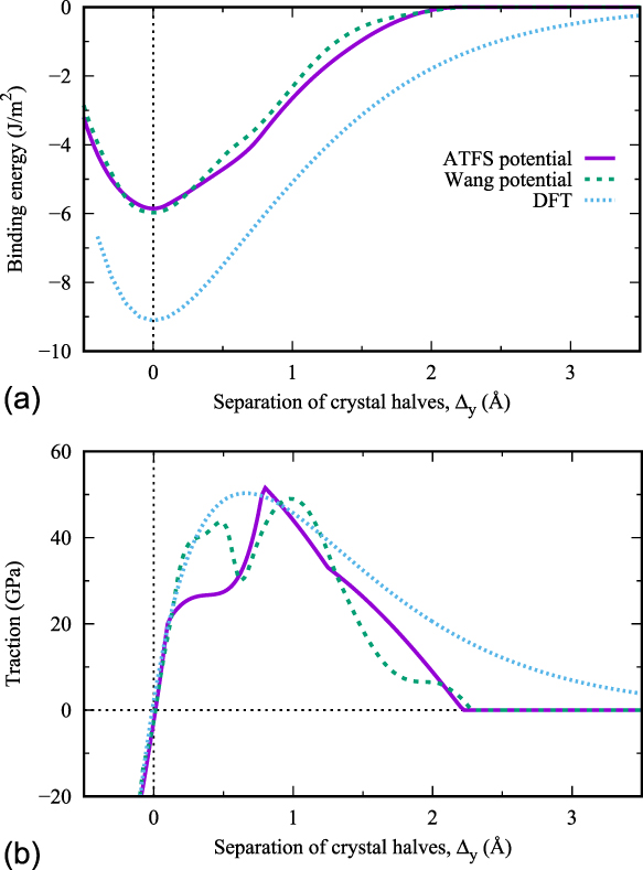
FIG. 2. (a) Binding energy versus separation of crystal halves for two different tungsten potentials and as obtained by DFT. (b) Derivatives of the binding curves, i.e., traction versus separation of crystal halves.
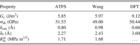
TABLE II. Summary of the characteristic values for rigid-body separations (cleavage energy G c, threshold stress σth, critical separation δcrit, final separation δf) and crack-tip configurations  $\left( {K_{{\rm{Ic}}}^{{\rm{at}}}} \right)$ obtained with the ATFSReference Finnis and Sinclair48,Reference Ackland and Thetford49 and WangReference Wang, Zhou, Li and Hou50 potentials as well as by DFT calculations.
The TS relationships for the different potentials were readily obtained by applying Eq. (1), i.e., by derivation of the binding-energy versus separation-distance data. The corresponding TS plots are shown in Fig. 2(b). Three characteristic values can be obtained from these plots: the threshold stress, σth, the critical separation distance δcrit (where σth is reached), and the ‘final’ distance δf (where the traction across the surface is zero). All characteristic values are summarized in Table II and compared to values obtained by DFT calculations.
Based on the experience with previous studies on RBS,Reference Tahir, Janisch and Hartmaier35,Reference Janisch, Ahmed and Hartmaier41 the shape of the TS relationships of the Wang potentials appears to be somewhat unexpected as it shows two local maxima and a local minimum at around Δy ≈ 0.65 Å. The origin lies in the not-completely-smooth energy–displacement curves [see Fig. 2(a)]. Both potentials were optimized to reproduce several material properties, but an interplanar separation along the [001] axis was not included. However, as we will see in Sec. III, it is sufficient if the TS law includes the peak stress, and this is reasonably well reproduced by both potentials.
2. Crack-tip simulations
The fracture toughness  $\left( {K_{{\rm{Ic}}}^{{\rm{at}}}} \right)$ values determined by atomistic simulations are summarized in Table II. According to the Griffith criterionReference Griffith65
 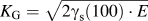 ${K_{\rm{G}}} = \sqrt {2{\gamma _{\rm{s}}}\left( {100} \right) \cdot E}$ (with E being the appropriate orientation-dependent elastic constant), critical values in the range of 1.61–1.64 MPa m1/2 are expected for both potentials. These theoretically expected values using the potential parameters are markedly smaller than the atomistically determined ones; see Sec. II. This well-known behaviorReference Gumbsch66 is generally attributed to the lattice-trapping effect.Reference Thomson, Hsieh and Rana67 The atomistic crack-tip configurations showing crack propagation by cleavage on the original (100) plane are provided in Fig. 3.

FIG. 3. Atomistic crack-tip configurations in the (100)[011] crack system for the ATFS (a) and Wang (b) potentials at the critical stress intensity factors  $K_{{\rm{Ic}}}^{{\rm{at}}}$; see Table II. The original crack-tip atoms are colored black.
3. Comparison of interatomic forces
There are different ways to calculate the force acting across the cleavage plane from the present simulation results:  $F_{{\rm{ct}}}^{{\rm{at}}}$ is the y-component of the individual atomic (superscript ‘at’) force vectors calculated during the simulation of crack-containing configurations (subscript ‘ct’). To compare the evolution of the crack-tip forces with the forces during rigid-body separations, the crack-tip distance r ij has to be related to the corresponding separation in the [100] direction, Δy, as follows:
 $${\Delta _y} = {{ - {a_0}} / 2} + \sqrt {r_{ij}^2 - {{a_0^2} / 2}} \quad ,$$
where a 0 denotes the bulk lattice parameter. Strictly, this correction is only valid under the assumption that the distance between next-nearest (NN) neighbors (and for cracks on the (100) plane NN neighbor bonds are the critical bonds) changes with Δy, as follows:
 $${r_{ij}} = \sqrt {2{{\left( {{{{a_0}} / 2}} \right)}^2} + {{\left( {{{\left( {{{{a_0}} / 2}} \right)}^2} + {\Delta _y}} \right)}^2}} \quad ,$$
i.e., when applying a homogeneous uniaxial strain without allowing Poisson contraction, as is the case in the present study.
 $F_{{\rm{rb}}}^{{\rm{at}}}$ is the y-component of the individual atomic force vectors calculated during the simulation of rigid-body separations (subscript ‘rb’). Since there are N surface interacting NN pairs and
  ${{{N_{{\rm{surface}}}}} \over 2}$ 2nd NN pairs for each (100) surface [Fig. 1(a)], the total force
  $F_{{\rm{rb}}}^{{\rm{at}}}$ per surface atom is obtained from the individual forces between NN and 2nd NN neighbors,
  $F_{{\rm{NN}}}^{{\rm{at}}}$ and
  $F_{2{\rm{NN}}}^{{\rm{at}}}$, by
 $$F_{{\rm{rb}}}^{{\rm{at}}} = F_{{\rm{rb,NN}}}^{{\rm{at}}} + {1 / 2}F_{{\rm{rb,2NN}}}^{{\rm{at}}}\quad ,$$
 $F_{{\rm{rb}}}^{{\rm{avg}}}$ is calculated from the change of the average potential energy per atom in rigid-body separations:
 $$F_{{\rm{rb}}}^{{\rm{avg}}} = {{{N_{{\rm{atoms}}}}} \over {2{N_{{\rm{surface}}}}}}{{{\rm{d}}{E_{{\rm{pot}}}}} \over {{\rm{d}}\Delta }}\quad ,$$
which corresponds to the calculation of the tractions in Eq. (1) but normalized to the number of surface atoms rather than the surface area.
F eff is the derivative of the effective pair potential.Reference Johnson68 In this case, the same correction regarding r ij and Δy has to be made as for the crack-tip forces; see Eq. (2).
The evolution of these forces as a function of lateral separation Δy is shown in Figs. 4(a) and 4(b) for the two potentials. The truly remarkable result of this comparison is how well the force laws from the by-far-simpler model systems (rigid-body separations and effective pair potential) agree with the actual forces at the crack tips, considering that the environments in which the forces have been determined (or calculated as in the case of F eff) are completely different.

FIG. 4. Comparison of the relationship between per-atom forces on crack-tip atoms  $\left( {F_{{\rm{ct}}}^{{\rm{at}}}} \right)$, the NN and 2NN contributions to the forces on atoms across the cleavage plane during rigid-body separations
  $\left( {F_{{\rm{rb}}}^{{\rm{at}}}} \right)$, the derivative of the average potential energy during rigid-body separations
  $\left( {F_{{\rm{rb}}}^{{\rm{avg}}}} \right)$, and the derivative of the effective pair potential (F eff) on the separation distance Δy (a) for the ATFS potential and (b) for the Wang potential.
Second, it should be noted that the unexpected camel-hump shape of the T(Δy) curve for the Wang potential shown in Fig. 2(b), which is essentially the per-area instead of per-atom versions of  $F_{{\rm{rb}}}^{{\rm{avg}}}\left( {{\Delta _y}} \right)$ and thereby
  $F_{{\rm{rb}}}^{{\rm{at}}}\left( {{\Delta _y}} \right)$, can now be understood by the separation of the total acting force into contributions from NN and 2nd NN neighbors.
Third, the individual force–separation relationships ( $F_{{\rm{rb}},{\rm{NN}}}^{{\rm{at}}}$ and
  $F_{{\rm{rb}},2{\rm{NN}}}^{{\rm{at}}}$) are very similar to each other, and their shape can be qualitatively understood by comparing it to the shape of the derivative of the effective pair potential, F eff. This implicitly shows that the correction made in Eq. (2) is applicable even if it does not account for changes in the electron density due to uniaxial straining, which might, however, be the reason for the minor differences in the magnitudes of
  $F_{{\rm{rb}},{\rm{NN}}}^{{\rm{at}}}$ and F eff.
An important conclusion which can be drawn from these results is that the forces necessary to break the bond between the crack-tip atoms show only a small—if any at all – dependence on the local atomic surrounding at the crack tip. Even if our observations cannot prove that all EAM potentials will show the same behavior or that crack-tip bonds in metals in general do not show a strong dependence on their local bonding environment, this is to our knowledge the first time that it has been shown that the forces to separate crack-tip atoms can indeed be estimated from simulations of rigid-body displacements. In particular, the comparison between  $F_{{\rm{ct}}}^{{\rm{at}}}$ and
  $F_{{\rm{rb}}}^{{\rm{avg}}}$ in Fig. 4 shows that the characteristics of TS laws derived from simple rigid-body separations, i.e., the maximum force and the critical separation distance δcrit, are in very good agreement with the actual crack-tip forces. This has important consequences for multiscale modeling, as it validates the long-standing use of DFT calculations to determine traction separation laws. Whether the correspondence of forces from rigid-body separation and fracture simulations still holds for systems with complex chemical compositions or grain- and interphase boundaries would still need to be shown. However, an averaging of forces over one structural or chemical unit would be a possible way to extend our approach.
III. ATOMISTICALLY INFORMED TRACTION SEPARATION (TS) LAW
A. Derivation of a scalable TS law
In this section, a method is derived to convert the atomic forces at the crack tip into meaningful continuum quantities, i.e., TS laws describing the cohesive behavior of the material in front of the crack tip. To accomplish this, we consider a chain of N pairs of atoms in front of the crack tip on the crack plane (see Fig. 5). The atom pairs under consideration are those that are affected by the stress concentration of the crack tip and that lie in the crack plane.
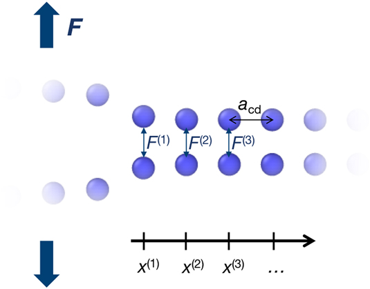
FIG. 5. Schematic drawing of the strained atom pairs in the CZ in front of the crack tip.
Formally, the atomic forces F (i), defined in Sec. II.B.2, can be converted into atomic stresses by normalization with the atomic area A at as
 $${\sigma _{{\rm{at}}}}\left( {{x^{\left( i \right)}}} \right) = {{{F^{\left( i \right)}}} \over {{A_{{\rm{at}}}}}}\quad ,$$
where x (i) = ia cd is the distance of the atom pair i = 1, 2, …, N to the crack tip and A at = a cfa cd is the projected atomic area on the crack plane, given by the interplanar distance a cf along the crack front and the interplanar distance a cd in crack direction, respectively. The crack itself is defined by the pairs of atoms that are separated by a distance of more than the critical displacement δf, such that the position of the crack tip is located at the last pair of atoms with a larger separation than δf. It is noted here that the elastic distortion of the atomic distances along the crack front and in the crack direction is neglected to obtain a closed-form solution for the scaling relation.
From LEFM, it is known that the stress field in front of a crack tip decays as  ${1 / {\sqrt {{x^{\left( i \right)}}} }}$. Figure 6(a) shows that this linear-elastic theory holds excellently at the atomic scale, even very close to the crack tip, in agreement with the findings of Ref. Reference Singh, Kermode, De Vita and Zimmerman9. The deviation for the crack-tip atom is partly due to the 20% increased Voronoi volume compared to the atoms in front of the crack tip. In contrast to the atomic stresses, the atomic forces are largest for the crack-tip atom pair. The atomic stresses along the cleavage plane in front of the crack tip can be reasonably expected to follow
 $${\sigma _{{\rm{at}}}}\left( {{x^{\left( i \right)}}} \right) = {\sigma _{{\rm{at}}}}\left( {{x^{\left( 1 \right)}}} \right)\sqrt {{{{x^{\left( 1 \right)}}} \over {{x^{\left( i \right)}}}}} = {{{F^{\left( 1 \right)}}} \over {{A_{{\rm{at}}}}}}\sqrt {{{{x^{\left( 1 \right)}}} \over {{x^{\left( i \right)}}}}} = {{{K_{\rm{I}}}} \over {\sqrt {2\pi {x^{\left( i \right)}}} }}\quad ,$$
with the stress intensity factor
 $${K_{\rm{I}}} = {{{F^{\left( 1 \right)}}\sqrt {2\pi {a_{{\rm{cd}}}}} } \over {{A_{{\rm{at}}}}}}\quad ,$$
fully defined by atomistic quantities.
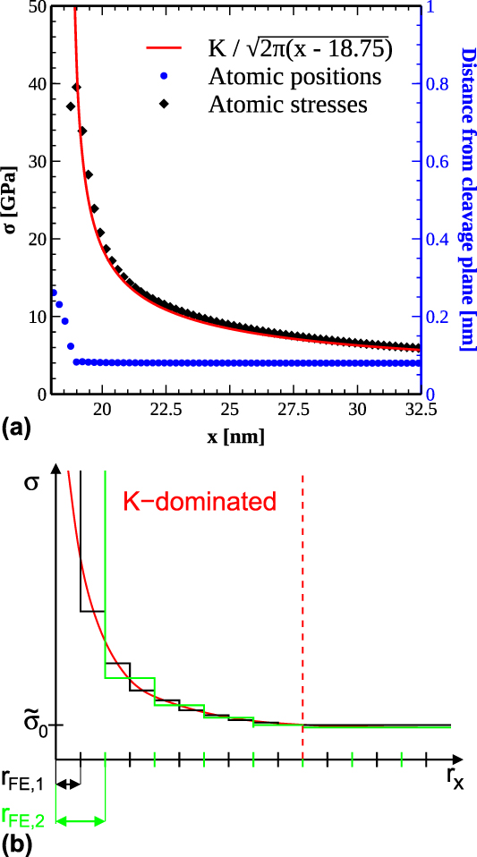
FIG. 6. (a) Atomic stresses (black diamonds) in front of the crack tip in the atomistic simulation using the Wang potential at a load of K I = 1.67 MPa m1/2 together with the corresponding analytic LEFM solution, which results in a finite stress at the boundary of our model. The blue points (color online) show the corresponding atom positions (right ordinate axis). (b) Schematic drawing of the stress, with step-wise functions, which indicate the average stress per element in FEM simulations with two different mesh sizes, FE1 and FE2. The region with a significant gradient in the average stress is called the K-dominated region. At the end of the K-dominated zone, the stress gradient decays into a constant far-field stress σ0, which needs to be considered for finite crack sizes; see Eq. (15).
The fundamental relation between the atomistic and the continuum description is demonstrated by calculating the fracture toughness K Ic from Eq. (8), as
 $${K_{{\rm{Ic}}}} = {{{F_{\rm{c}}}\sqrt {2\pi {a_{{\rm{cd}}}}} } / {{A_{{\rm{at}}}}}} = \sigma _{\rm{c}}^{{\rm{at}}}\sqrt {2\pi {a_{{\rm{cd}}}}} \quad ,$$
with the critical force F c at which the bond between the first pair of atoms breaks; i.e., this pair of atoms is separated beyond the critical distance δf, and consequently the crack tip advanced by one atomic distance. This force corresponds to the theoretical strength defined in Sec. II.B.1 and can thus be conveniently calculated with atomistic methods. With the values obtained from atomistic calculations with the Wang potential (see Table II), a fracture toughness of K Ic = 1.70 MPa m1/2 is calculated from the critical force,  $F_{{\rm{rb}},{\rm{max}}}^{{\rm{avg}}}$, and K Ic = 1.84 MPa m1/2 from the theoretical strength σth with
  ${a_{{\rm{cd}}}} = {{{a_0}} / {\sqrt 2 }}$. The force-based value corresponds very well to the K Ic values obtained from direct atomistic simulation (
 $K_{{\rm{Ic}}}^{{\rm{at}}} = 1.68$ MPa m1/2) and from the Griffith criterion (
 $K_{{\rm{Ic}}}^{\rm{G}} = 1.64$ MPa m1/2). The value from the critical strength is roughly 8% higher as can be expected from the difference in
  $F_{{\rm{eff}}}^{{\rm{max}}}$ and
  $F_{{\rm{rb}},{\rm{max}}}^{{\rm{avg}}}$ (see Fig. 4).
However, for most continuum fracture models, a fracture energy or WoS is required in addition to the fracture strength  ${\tilde{\sigma }_{\rm{c}}}$ and a critical separation
  ${\tilde{\delta }_{\rm{c}}}$. These parameters represent the main quantities defining the TS law describing the cohesive behavior of a material in front of a crack tip [see Fig. 6(b)]. While the WoS is scale independent, the fracture strength and the critical separation both depend on the spatial resolution of the applied method. The fundamental material constants are obtained from atomistic methods, but a proper scaling must be developed for the scale-dependent model parameters that takes an appropriate length scale or mesh size into account, as outlined in the introduction.
Since all values used in continuum methods represent average values over a finite volume or a FE, we start by defining the critical fracture strength as average stress over the K I-dominated region
 $${\tilde{\sigma }_{\rm{c}}} = {{\sum\limits_{i = 1}^N {{F^{\left( i \right)}}} } \over A}\quad ,$$
as the sum over all atomic forces in this region normalized by the corresponding area. From relation Eq. (7), we also conclude that the atomic forces decay as
 $${F^{\left( i \right)}} = {F^{\left( 1 \right)}}\sqrt {{{{x^{\left( 1 \right)}}} \over {{x^{\left( i \right)}}}}} = {{{F^{\left( 1 \right)}}} \over {\sqrt i }}\quad .$$
With Eq. (11), the relation A = NA at and the condition that F (1) = F c, because the onset of crack advance is considered, we obtain
 $${\tilde{\sigma }_{\rm{c}}} = {{{F_{\rm{c}}}\sum\limits_{i = 1}^N {{1 \over {\sqrt i }}} } \over {N{A_{{\rm{at}}}}}} = \sigma _{\rm{c}}^{{\rm{at}}}{1 \over N}\sum\limits_{i = 1}^N {{1 \over {\sqrt i }}} \quad .$$
The sum on the right hand side of this equation can be approximated by
 $$\tilde{S}\left( N \right) = {1 \over N}\sum\limits_{i = 1}^N {{1 \over {\sqrt i }}} \approx {2 \over {\sqrt N }} - {{1.4} \over N}\quad .$$
 Numerical evaluation of the approximation shows that the relative error is less than 10−4 for values of N between 105 and 106; for the latter value, the sum amounts to  $\tilde{S}\left( N \right) = 0.002$. The precision of the approximation gets better for larger values of N, which is the usual case for applications. Since the sum is finite, a precise numerical evaluation is always possible, although the simple approximation function is still easier to handle.
To calculate a properly scaled final separation of atoms  ${\tilde{\delta }_{\rm{f}}}$, we consider a simple bilinear TS law [see Fig. 7(b)] such that
 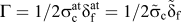 $\Gamma = {1 / {2\sigma _{\rm{c}}^{{\rm{at}}}}}\delta _{\rm{f}}^{{\rm{at}}} = {1 / 2}{\tilde{\sigma }_{\rm{c}}}{\tilde{\delta }_{\rm{f}}}$. It follows
 $${\tilde{\delta }_{\rm{f}}} = {{2\Gamma } \over {{{\tilde{\sigma }}_{\rm{c}}}}} = {{\delta _{\rm{f}}^{{\rm{at}}}} \over {\tilde{S}\left( N \right)}}\quad .$$
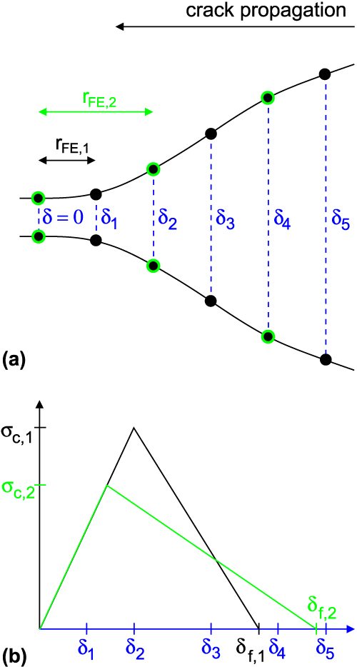
FIG. 7. (a) Schematic drawing of the region around a crack-opening sampled by elements of different sizes r FE. At each node, the crack opening is characterized by a δ. (b) Bilinear TS law in which critical stress and final displacement depend on the mesh size.
In the final step, a reasonable estimate for the length of the K-dominated region and thus the number N of atom pairs to consider is developed. The criterion for the length of this region is the decay of the stress to a value of σ0, which can be either the yield strength of a plastic material or the far-field stress  ${\sigma _0} = {{{K_{\rm{I}}}} / {\sqrt {\pi {a_{{\rm{crack}}}}} }}$ considered in linear-elastic fracture mechanics, where a crack is the crack length. Hence, N is defined by the requirement that
 $${{{F^{\left( N \right)}}} \over {{A_{{\rm{at}}}}}} = {{{F^{\left( 1 \right)}}} \over {{A_{{\rm{at}}}}\sqrt N }} = {\sigma _0}\quad .$$
For the critical condition, when the crack starts to propagate (F (1) = F c), we obtain
 $${N_{\rm{c}}} = {\left( {{{{F_{\rm{c}}}} \over {{\sigma _0}{A_{{\rm{at}}}}}}} \right)^2} = {\left( {{{\sigma _{\rm{c}}^{{\rm{at}}}} \over {{\sigma _0}}}} \right)^2}\quad .$$
Noting that the critical atomic stresses are typically a 1000 times larger than the yield strength or far-field stress, a reasonable estimate for the number of atom pairs in the K-dominated region is N c ≈ 106. This yields a size of K-dominated zone r coh = N ca cd ≈ 200 μm.
In summary, a scaling relation for the atomistic strengths and separations has been derived, in the form
 $${\tilde{\sigma }_{\rm{c}}} = \kappa \sigma _{\rm{c}}^{{\rm{at}}}\quad ,$$
 $${\tilde{\delta }_{\rm{f}}} = {{\delta _{\rm{f}}^{{\rm{at}}}} \over \kappa }\quad ,$$
with the scaling factor
 $$\kappa = \tilde{S}\left( N \right) = {2 \over {\sqrt N }} - {{1.4} \over N} = 2{{{\sigma _0}} \over {\sigma _{\rm{c}}^{{\rm{at}}}}} - 1.4{\left( {{{{\sigma _0}} \over {\sigma _{\rm{c}}^{{\rm{at}}}}}} \right)^2}\quad .$$
For practical applications, N is replaced by the ratio of the size of each element to the lattice parameter in crack propagation direction, and Eq. (19) becomes
 $${\kappa _{{\rm{FE}}}} = 2\sqrt {{{{a_{{\rm{cd}}}}} \over {{r_{{\rm{FE}}}}}}} - 1.4{{{a_{{\rm{cd}}}}} \over {{r_{{\rm{FE}}}}}}\quad .$$
This results in a critical stress and a final displacement, which are both adjusted to the element size, as shown in Fig. 7(b).
It is noted that the directional dependence of the model parameters in Eq. (20) is artificially introduced by the scaling of the FE size with the atomic interplanar distance in the crack propagation direction. A proper directional dependence could be introduced by using a direction-sensitive energy release rate as WoS.
B. Application and validation
As an application of the novel scaling relation, we conducted FE fracture simulations for a linear elastic material representing tungsten to calculate the fracture toughness K Ic. The numerical simulations have been performed using the commercial FE software ABAQUS. All simulations have been performed using an implicit time integration scheme. The surface-based CZ method is used to simulate fracture. The geometry of the model is the same as in the atomistic simulation [see Fig. 1(b)], whereas the ratio between the radius of the sample and the mesh at the crack tip is kept constant at 10,000. This is done to avoid the variation of results due to mesh-size variation in comparison to the sample size. This mesh size is applied to the area around crack tip up to 1% of the total size of the model and then increased gradually toward the outer boundary of the specimen to avoid too much computational cost. The geometry has been meshed with fully integrated 4-node quadratic elements with linear shape functions (CPE4) for the plane strain case. The mechanical boundary conditions have been applied as K I-displacement field in a similar way as in the atomistic simulations. This is achieved by selecting the outermost nodes of the FE model and applying the boundary conditions to those nodes. Isotropic elastic constants, Young’s modulus E and Poisson ratio ν, were determined according to the elastic constants for the Wang potential in Table I, which yields E = 410 GPa and ν = 0.281.
A series of FE simulations has been performed for K I loading using scaled parameters for the TS law according to different mesh sizes, i.e., the scaled critical stress  ${\tilde{\sigma }_{\rm{c}}}$, and the displacement at failure
  ${\tilde{\delta }_{\rm{f}}}$ according to Eq. (20). The value for the initial slope of the TS law has been kept constant at 1.634 × 10⁵ GPa for all cases. The fracture toughness K Ic is defined as the loading at which the first cohesive surface element breaks (δ ≥ δf).
In Fig. 8(a), it can be seen that the values of scaled critical stresses decrease over several orders of magnitude with the increasing mesh size. The values of final displacements (not shown) increases correspondingly to keep the cleavage energy (WoS) constant.
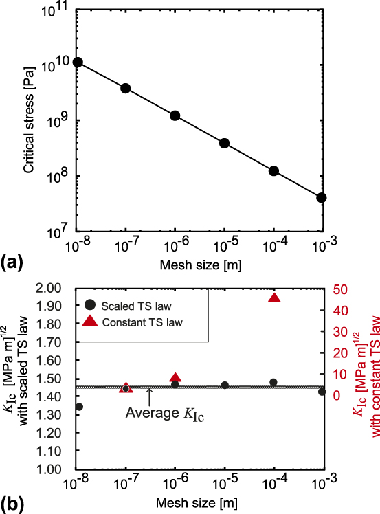
FIG. 8. (a) Scaling of the model parameter of the TS law with the mesh size. (b) Fracture toughness resulting from a FE simulation for a linear elastic material law with the properly scaled TS law (left ordinate axis) and with constant TS law (right ordinate axis) for the cohesive behavior.
Figure 8(b) shows the obtained values of K Ic for different mesh sizes. The value K Ic varies between 1.35 and 1.49 MPa m1/2 over variation of mesh size by 5 orders of magnitude. The average of the K Ic values over the range of mesh sizes is 1.45 MPa m1/2, which is close to the atomistic value  $K_{{\rm{Ic}}}^{{\rm{at}}} = 1.68$ MPa m1/2. This is remarkable because there is no fitting of parameters, but rather a consistent scaling of the atomistic quantities according to the mesh size over a range of five orders of magnitude. It can be seen that there is no pronounced scatter around the average value in the sense of a pronounced mesh-size dependence. To emphasize the importance of our scaling procedure, the calculation of K Ic with a constant TS law was also performed. In this case, the scaling is done only for the 10−7 m mesh and the same parameters for the TS law are used for the calculation of K Ic with the 10−6 m mesh (4.59 MPa m1/2) and the 10−4 m mesh (45.82 MPa m1/2). It can be seen in Fig. 8(b) that in this case the critical stress intensity factor scales with the square root of the mesh size (or in other words, the size of the sample), in agreement with the observation of BazantReference Bažant69 of K Ic variation for self-similar geometries but different sizes.
IV. CONCLUSIONS
In the strong stress gradient ahead of the crack tip, the definition of mechanical stress is necessarily scale-dependent. Thus, only fundamental atomistic methods provide a rigorous way to define stress-related material properties, e.g., the fracture strength.
In this work, it is shown that the widely used approach to derive the critical bond separation stress from ab initio calculations of RBSs is well justified. To accomplish this, we have compared forces occurring in atomistic simulations of RBS with those at crack tips under K I loading. The results demonstrate that they are indeed equivalent, which means that they are less environment-dependent than commonly expected. As a consequence, we can derive meaningful TS laws from much simpler model systems than from actual fracture simulations. This enables the use of computationally expensive, but quantitatively reliable methods such as ab initio DFT calculations.
Since the mesh sizes commonly used in continuum methods do not resolve the high atomistic stresses and the strong stress gradient at crack tips, we have introduced a physically meaningful approach to scale atomistic TS laws with the mesh size. It is based on the insight that the atomistically determined stresses ahead of the crack tip agree well with the prediction of LEFM. The approach defined in this work is based on properly averaging atomic forces over cohesive surface elements to convert them in mechanical stresses. This enables the use of fundamental atomistic material constants, such as theoretical strength, theoretical final separation, and work of separation as parameters in continuum fracture models.
It has also been demonstrated that the fracture toughness resulting from the thus-parameterized continuum model is independent of the mesh size, although numerical fluctuations occur. In this way, the atomistic data can be used directly to calculate TS parameters for continuum fracture models, such as CZ models or XFEM.
In our approach, the fracture model describes only the bond-breaking processes during cleavage; any additional (plastic) energy dissipation needs to be taken into account in the constitutive model of the material surrounding the crack. Therefore, the scaling method is ideally used in conjunction with micromechanical plasticity models or discrete dislocation dynamics simulations.
As ab initio tensile tests can be carried out using complex chemical compositions and including grain or interphase boundaries, the scheme enables the material-specific atomistically informed continuum modeling of fracture of engineering materials.
ACKNOWLEDGMENTS
EB gratefully acknowledges the funding from European Research Council (ERC) under the European Union’s Horizon 2020 research and innovation programme through the project “microKIc—Microscopic Origins of Fracture Toughness” (grant agreement No. 725483). AH and JJM gratefully acknowledge funding by the Deutsche Forschungsgemeinschaft (DFG) through Projects C3 and C4 of the collaborative research center SFB/Transregio 103 superalloy single crystals under grant number INST 213/747-2.


 Open access