

I. INTRODUCTION
Smart clothing is a new trend in wearable technology aimed at improving human life and satisfaction. Such clothing is made using combinations of micro-electronics embedded in fabrics to create functional and fashionable solutions that meet people's everyday needs. An area of interest is assisted living (AL), which takes into consideration the delicate needs of elderly individuals. In many countries, such as the USA and European Union (EU) countries, modern medicine has increased the longevity of people's lives. However, such countries are also experiencing a decreasing birth-rate that is leading to a disproportionate amount of people aged 65 and above when compared to the younger working population [Reference Florez-Revuelta and Chaaraoui1]. With current trends, it is estimated that, in the next 30 years, the elderly (i.e. individuals aged 65 or older) will outnumber their younger counterparts in the EU, for example, two to one [2]. This phenomenon will create a higher demand for AL solutions that can be used to provide long-term care to the aging population [Reference McCall3].
The primary objective of AL technologies is to improve lives by providing security, comfort, and independence [4]. These technologies can be applied to different environments, from homes and offices to outdoor public facilities [5–Reference Long, Joonsung, Seulki, Taehwan, Kiseok and Hoi-Jun16]. However, devices used in an AL system requires a continuous source of power which can be provided by supportive batteries (e.g. lithium-ion batteries) [Reference Yoo, Long, Seulki, Yongsang and Hoi-Jun17]. However, currently available batteries cannot always meet the demands of the devices that make up an AL system [Reference Xue, Cheng and Je18]. That is, prolonged use of an AL system's devices eventually requires battery recharging and replacement, which can be a tedious, expensive, and complicated task for the elderly and other individuals [Reference Baig, Gholamhosseini and Connolly15]. For example, replacing batteries in biomedical implants is expensive and a complex procedure. Research into energy harvesting [Reference Palazzi19–Reference Panatik21], wireless charging [Reference Jeremiah and Chukwuemeka22–Reference Guo26], battery and power management [Reference Heacock and Fundaro27–Reference Zhang, Song, Wang, Zhang, Wang and Li29] has been conducted for AL systems to improve the functionality and efficiency of device batteries.
Wireless charging offers a great solution to the problems with batteries as described above. For example, this way of charging batteries can be more convenient to a user of an AL system than wired charging and some early examples have been demonstrated [Reference Xue, Cheng and Je18], [Reference Wang, Nishino and Teo30], and [Reference Costanzo and Masotti31]. To address safety concerns of the technology, regulations and standards of implementing wireless power transfer (WPT) for charging should also be considered [32–Reference Lu, Wang, Niyato, Kim and Han38]. Currently, two main commercial WPT standards exist: (i) the Qi standard created by the wireless power consortium (WPC) and (ii) the A4WP standard the air fuel alliance (AFA). Both standards enable wireless charging techniques that use magnetic induction to transfer power from a transmitter (Tx) to a corresponding receiver (Rx) within a target device. WPC's Qi and AFA's A4WP standards are discussed extensively in [Reference van Wageningen and Staring39–41]. The two standards meet the international and regional regulations on safety and electromagnetic interference set up by government and health agencies [32]. Safety considerations are made by selecting a non-radiative WPT system design described in [Reference Mehdipour, Moarref, Kia and Yazdanipour42–Reference Catrysse, Puers, Hertleer, Van Langenhove, Van Egmond and Matthys50]. More specifically, the research presented in this paper is directed to exploring the design of a WPT system for wirelessly charging a wearable heating belt.
The challenges faced by these wirelessly charged devices include: (i) electromagnetic safety levels that lead to regulatory restrictions, which require a low power source with higher transmission efficiency [Reference RamRakhyani, Mirabbasi and Chiao47]; (ii) limited range of operation, which leads to positioning issues of the transmitter and receiver [Reference Borges Carvalho48]; and (iii) problems with integrating the transmitter and receiver in a seamless way to the user's everyday environment [Reference Sardini and Serpelloni49, Reference Catrysse, Puers, Hertleer, Van Langenhove, Van Egmond and Matthys50].
Works in [Reference Xue, Cheng and Je18], [Reference Wang, Nishino and Teo30], [Reference Kurs, Karalis, Moffatt, Joannopoulos, Fisher and Soljiacic51–Reference Wu, Wang, Yerazunis and Teo54] have also demonstrated high power transmission efficiency (PTE) using different approaches. For example, using small biomedical implant coils a PTE of 58% was achieved in [Reference Xue, Cheng and Je18]. Metamaterials have also been used to increase PTE in medium power applications [Reference Wang, Nishino and Teo30]. In [Reference Hatanaka52] and [Reference Pu and Hui53], a transmitter coil array was used to improve PTE to up to 85 and 50%, respectively.
Positioning issues have also been researched and overcome using different techniques in some works in [Reference Hatanaka52], [Reference Pacini, Mastri, Trevisan, Masotti and Costanzo55], [Reference Kim, Kim, Kim and Park56], and [Reference Jolani, Yu and Chen57]. In [Reference Hatanaka52], primary coils were embedded into a desk surface which significantly improved the charging area. Further, [Reference Pacini, Mastri, Trevisan, Masotti and Costanzo55] used a sequence of switchable couples of coils to adopt a transmitting link side that retains its coupling coefficient for a continuously moving receiver. In [Reference Kim, Kim, Kim and Park56], a similar concept to [Reference Hatanaka52] was adopted using magnetically coupled resonant wireless power, while [Reference Jolani, Yu and Chen57] used a bowl-shaped transmitter coil for free positioning.
In our proposed design as reported in this paper, which is based on the widely accepted Qi wireless charging standard, the transmitter of the WPT system is integrated within a backrest of a chair, while the WPT system's receiver is integrated in the user's belt together with a novel far-infrared heating element (see Figs 1(a) and 1(b)). The belt can be charged while its user is seated in the chair. This paper also investigates and examines alignment and power transfer conditions of the charging area on a chair's backrest, considering different coil arrangements and arrays. The WPT system proposed can also be used in multiple charging scenarios, including AL environments. In this way, the proposed WPT charging and heating system can be seamlessly integrated into the user's life with ease and comfort.
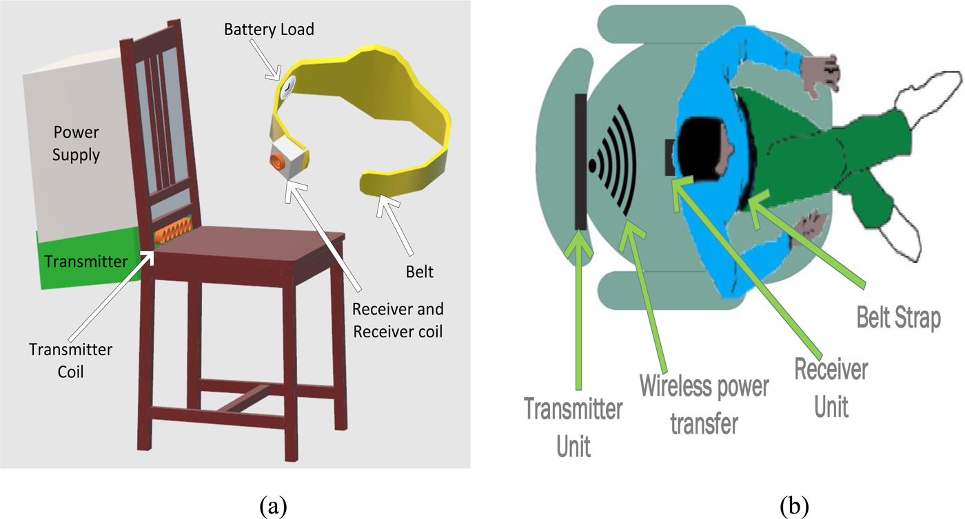
Fig. 1. (a) Illustration of the wireless power system to power a belt and integration into a chair. (b) Setup showing the working concept of the WPT system when the user is sitting on the chair. The actual wearable belt can be seen in Fig. 2.
II. WIRELESS SYSTEM DESIGN
The major factors that affect the performance of the WPT system described herein are: (i) distance and misalignment between the transmitter and receiver; and (ii) power transfer between the transmitter and receiver. Both are attributable to inductive power transfer, which is specified by the Qi standard [Reference van Wageningen and Staring39]. Table 1 shows the initial design constraints of the system.
Table 1. System specifications.
When the separation distance of the coils for the system is smaller than 1/10th of the wavelength of magnetic field, an Equivalent Lumped Parameter Circuit Model of the system can be made as further described in [Reference Hariri, Berzoy, Mohamed and Mohammed58].
The first constraint requires that the receiver to be near the transmitter of the WPT system. More specifically, and as shown in Fig. 1(b), the belt to be charged (which includes the receiver) must be close to the chair's backrest (which includes the transmitter). Furthermore, the second constraint requires power transfer in our WPT system to occur at any sitting position. The proposed WPT system overcomes the constraints described above by using an array of coils to be embedded in the backrest of the chair (previously shown in Fig. 1) and as similarly used in [Reference Hatanaka52] and [Reference Kim, Kim, Kim and Park56]. Thus our proposed design as described in Fig. 2 can increase the coverage area for WPT.
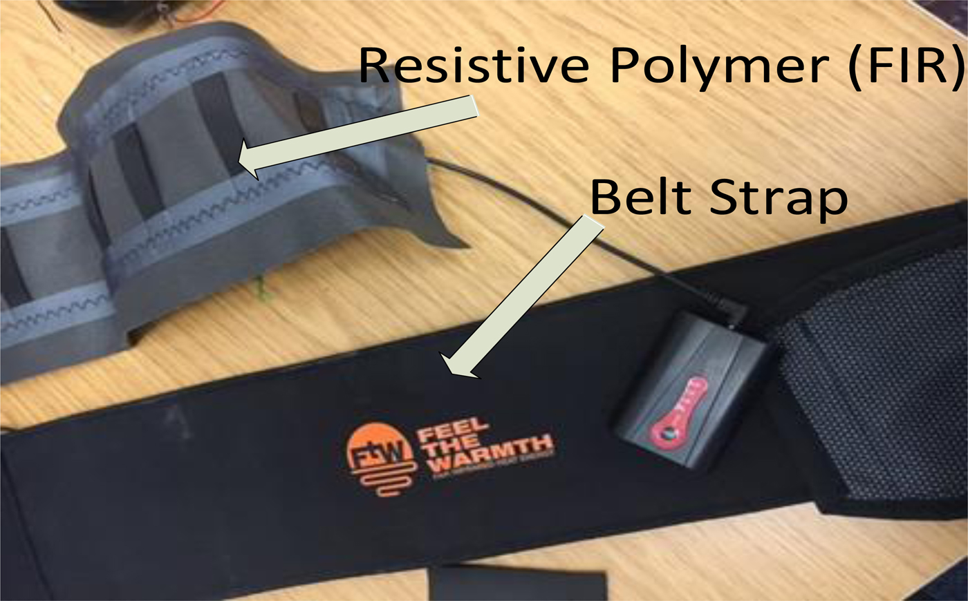
Fig. 2. Wearable belt with the charging element.
The main design constraints of the coil size of the system include the physical dimensions of the belt (for the receiver) and load (li-ion battery pack). The battery has a nominal input voltage of 7 V and an input power of 5 W as specified in [59].
Our design process is shown in Fig. 3 and physical dimensions of the coils were used as initial input parameters to calculate the required self-inductance of the coils and mutual inductance by the theory reported [Reference Buchmann60], which was then optimized based on the power transfer efficiency (PTE). The receiver coil had restrictions due to the belt size while there were no size constraints for the transmitter, other than it needed to fit within a chair.
 $$\eta = \displaystyle{1 \over {1 + \left[ {A\displaystyle{{R_1} \over {R_L}}} \right] + \left[ {R_2\displaystyle{{R_L} \over {{\lpar {wL_2} \rpar }^2}}} \right]}}. $$
Fig. 3. Flowchart of the design methodology for the proposed WPT system.
The circuit was then tuned to obtain the resonant capacitors for the primary and secondary coils by following [Reference Johns, Antonacci and Siddabattula61]. These parameters were then used in the simulation environment for further optimization and where the Keysight software Advanced Design System (ADS) was employed.
A) Transmitter parameters
The transmitting unit is based on the WPC1.1 Qi specification with a 5W power level [62]. A WPC A29-type coil was used and characterized with parameters as in [63]. The transmitter coil is fabricated from litz wire with nylon spinning having 180 strands of no. 40 AWG (0.08 mm diameter). The measured inductance and quality factor of the transmitter coil were 10 µH and 90, respectively. A ferrite sheet was placed underneath the coil to shield the electronics in the base of the charger [64].
B) Receiver parameters
The design constraints for the individual receiving coil (32 × 48 mm2) was more due to the limited dimensions of the textile belt. During the initial design phase, efforts were made to ensure that the employed receiver coil was able to provide a suitable mutual inductance [65] and thus provide sufficient coupling; i.e. the coil had an inductance of 15 µH and a quality factor of 60 (Fig. 4 illustrates the design process in terms of size, load resistance and coupling distance). Table 2 shows the performance data of the transmitter and receiver modules.
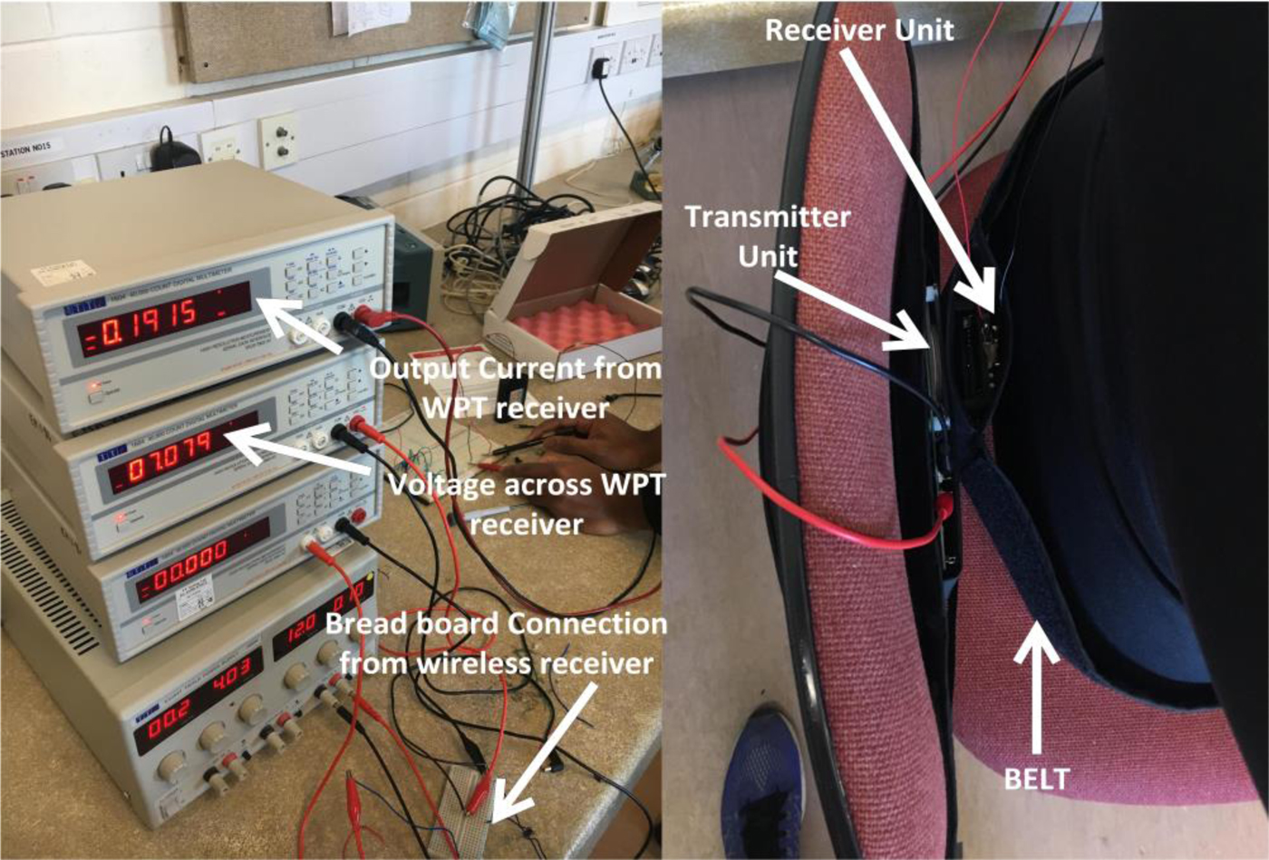
Fig. 4. Left side shows measurement equipment and setup. Right side shows the wireless power system operating in the belt and a chair.
Table 2. Relevant parameter for selected transmitter and receiver units.

III. WIRELESS POWER DESIGN
The wireless system transmits power from a transmitter embedded in a chair then a belt containing the receiver unit receives and harvests the power. The harvested power is used to provide a regulated supply voltage suitable for charging the lithium-ion battery. The connection between the battery and the receiver has been implemented on a breadboard. Voltmeters and ammeters were connected to allow power consumption to be measured, as shown in Fig. 4.
IV. SYSTEM MODELING AND SIMULATION
Modeling the wireless power system (transmitter and receiver modules) through a simulation tool is an important part of the design before implementing the physical system. This kind of simulation-based approach can help to estimate and quantify expected outcomes of the real time experimentation. The simulation software Keysight ADS was used to obtain the power output at the receiver for any coupling condition using coil types of the chosen transmitter and receiver modules.
The transmitter and receiver modules operated using inductive coupling regulated by the Qi standard which operates at frequencies between 100 and 200 kHz. The transmitter module is made up of an oscillator capable of producing the required resonant frequency. An amplifier then drives alternating current into the primary coil. The receiver converts the signal to DC through rectifying circuits [Reference van Wageningen and Staring39].
The combination of the BQ500215EVM-648 wireless power transmitter and the BQ51025EVM-649 receiver shown in Fig. 8 are expected to give an output of 7 V at a maximum current of 1 A.
A) Coupling factor and coil modeling
Coupling factor quantifies the strength of magnetic field generated by the transmitter coil and it varies between 0 and 1. It must be noted that, when k = 1 this represents perfect coupling. Coupling is also highly dependent on the distance between the coils as will be shown in the paper.
From [66] and [67] the inductance of the transmitter and receiver modules were obtained respectively to calculate the coupling coefficient, k, before calculating the mutual inductance between the coils, M. Also, the coupling factor can be measured from an existing system as a relative open loop voltage, u, it can be given as follows from (5a) in [Reference Johns, Antonacci and Siddabattula61]:
 $$u = \displaystyle{{U_2} \over {U_1}} = k\sqrt {\displaystyle{{{\rm \;} L_{22}} \over {L_{11}}}}, $$
where U 1 and U 2 are the voltages applied to coil, L 11 is the self-inductance of the transmitter coil, and L 22 is the self-inductance of the receiver coil. These parameters are also related to the general set of equations for coupled inductors as seen in [Reference Waffenschmidt68]:
 $$\displaystyle{{U_1} \over {j\omega}} = L_{11}I_1 + MI_2 = L_{11}I_1 + \Phi _{12},$$
 $$\displaystyle{{U_2} \over {j\omega}} = MI_1 + L_{22}I_2 = {\rm \Phi} _{21} + L_{22}I_2.$$
Inserting equation (2) into equations (3) and (4) we get the following:
 $$\displaystyle{{U_1} \over {j\omega}} = L_{11}I_1 + \Phi _{12},$$
 $$\displaystyle{{U_2} \over {j\omega}} = {\rm \Phi} _{21} + L_{22}I_2.$$
These equations show that the voltage can be expressed in the form of flux density. This condition is possible when the transmitting and receiving coils are coupled strongly with each other, in other words, a very small distance is separating them [Reference Ohira69]. The overall measured inductance is given by L S in [Reference Johns, Antonacci and Siddabattula61], which is:
 $$L_S = L_{11} + L_{22} + (2M).$$
B) Resonant capacitors
The receiver circuit has two resonant capacitors C s, and a series resonant capacitor and C sp. These capacitors along with the receiver coil make up a dual resonant circuit. The two capacitors are used to tune the receiver coil and by the Qi standard, should be sized correctly based on the WPC specification [62], and where the receiver coil is then placed on the spacer, and L rx is measured with a stimulus of 1-V RMS and 100 kHz. These capacitors can be further calculated using the 100 kHz resonant frequency:
 $$C_p = \displaystyle{1 \over {{\lsqb {100kHz\; \; 2\pi} \rsqb }^2\; L_p}}\;, C_s = \displaystyle{1 \over {{\lsqb {100kHz\; \; 2\pi} \rsqb }^2\; L_S}}, $$
and C sp is the secondary resonance considering 1 MHz:
 $$C_{sp} = \displaystyle{1 \over {{\lsqb {1MHz\; \; 2\pi} \rsqb }^2\; \; \left[ {L_S-\displaystyle{1 \over {C_s}}} \right]}}.$$
The quality factor must also be >77 after tuning and is given by:
 $$Q = \displaystyle{{1MHz\; \; 2\pi \; \; L_S} \over R},$$
where R is the resistance of the coil. Table 3 below shows data calculated for the circuit modeling.
Table 3. Data for simulation setup.
C) PTE simulations
Figure 5(a) shows the circuit schematic of the modeled wireless power system while Fig. 5(b) shows the ADS schematic of the system. This simulation model is expanded on and based on the reported findings from [Reference Solar, Alonso, Bustamante and Giers70]. The source is an oscillator which generates the AC signal at 100 kHz that flows into the transmitter coil, L p generates an oscillating magnetic field, C p is the resonant capacitor calculated from equation (8) that generates a resonance for L p with a coil resistance of R equation (10). Through the mutual induction tool from ADS, energy from the magnetic field induces AC current in the receiver coil, L s.
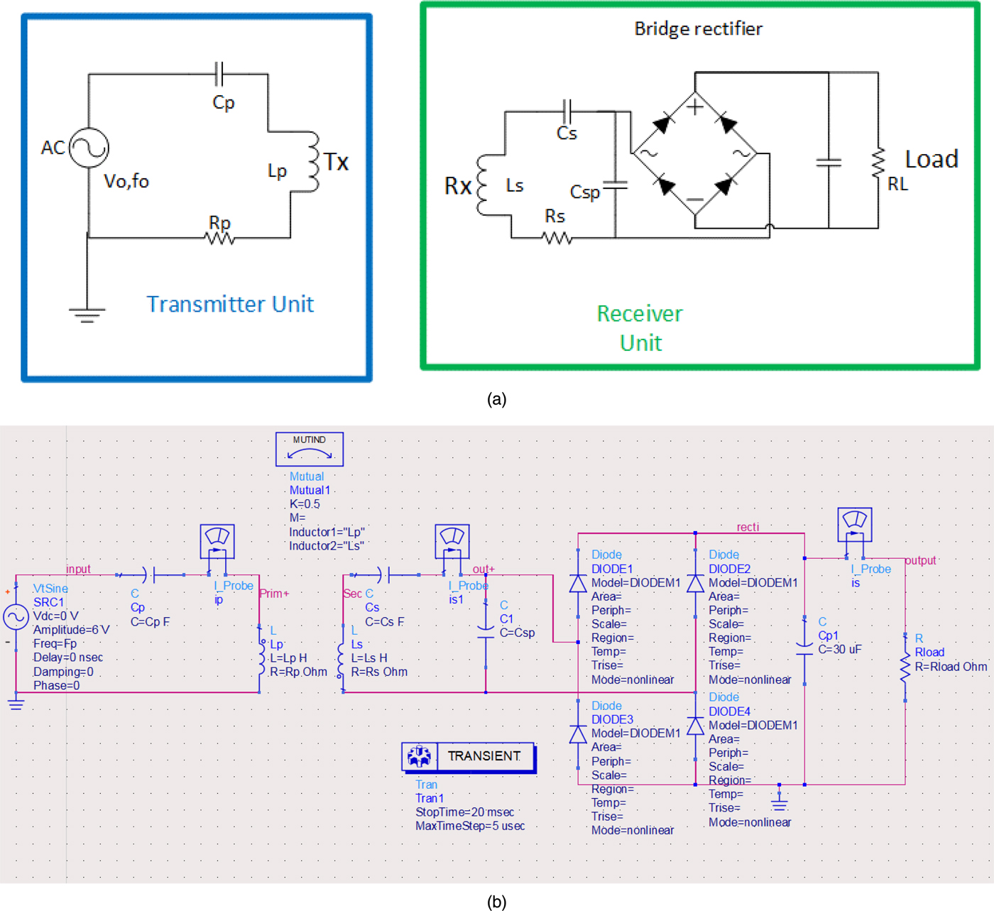
Fig.5. (a) Circuitry of the receiver and single coil transmitter units. (b) ADS simulation model illustrating receiver circuit and the single coil transmitter.
At the receiver the conventional bridge diodes made of Schottky diodes, convert the signal to DC. C s is the series resonant capacitor calculated in equation (8) while C sp is the parallel resonant capacitor calculated in equation (9) for the receiver coil under test. This receiver model is based on the Qi specification in [63] for type A5.
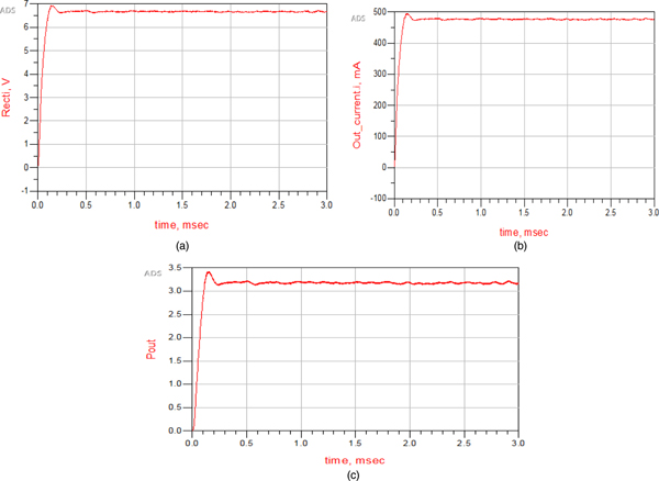
Figure 6 shows the rectified voltage of a 15 Ω load to be between 6.7 and 7 V. The current is between 500 mA (0.5 A) and 460 mA (0.46 A). The output power was tabulated for a load resistance ranging from 3 to 200 Ω.
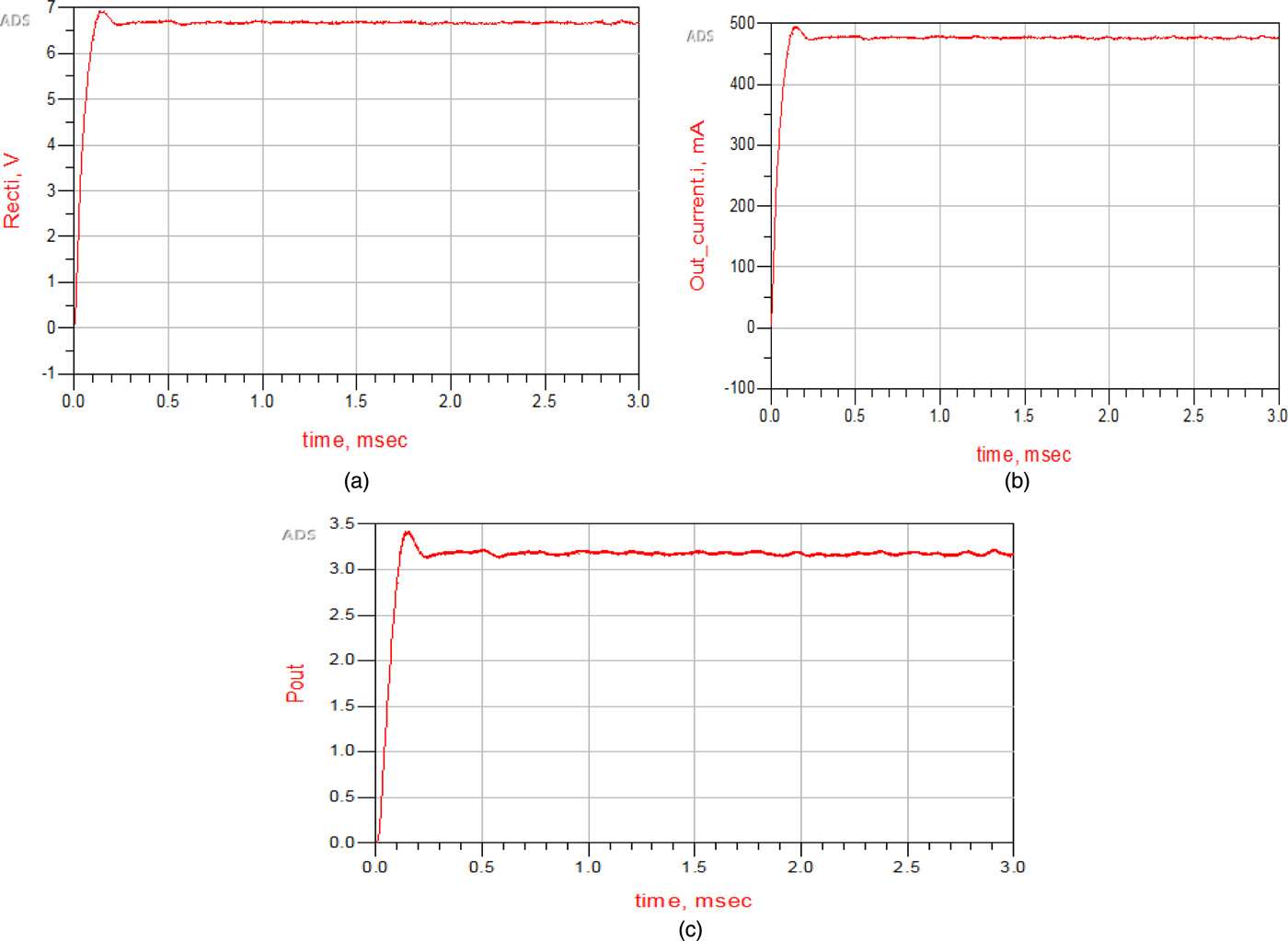
Fig. 6. ADS simulation results at 15 Ω: (a) voltage, (b) current, and (c) power.
The lithium ion battery used in our system has a high resistance at full charge. Also, to measure the impedance, a battery must be at least 50% charged in practice. A completely drained or nearly empty battery has a high internal resistance. As the battery reaches 50% state-of-charge (SOC), the resistance drops and then increases again towards full charge [Reference Buchmann60]. Table 4 shows the output efficiency of the system when charging the battery for increasing resistance as SOC increases towards full charge at 200 Ω. At a low charge, the system has higher and over time the efficiency drops as the battery continues to charge.
Table 4. Output result from simulation.
D) Misalignment calculations
Simulations for different alignment conditions were done in MATLAB using equation (22) from [Reference Khan, Pavuluri and Desmulliez71]. The translational misalignment, d tm was simulated at a varying distance of separation, d r between the coils as shown in Fig. 7.
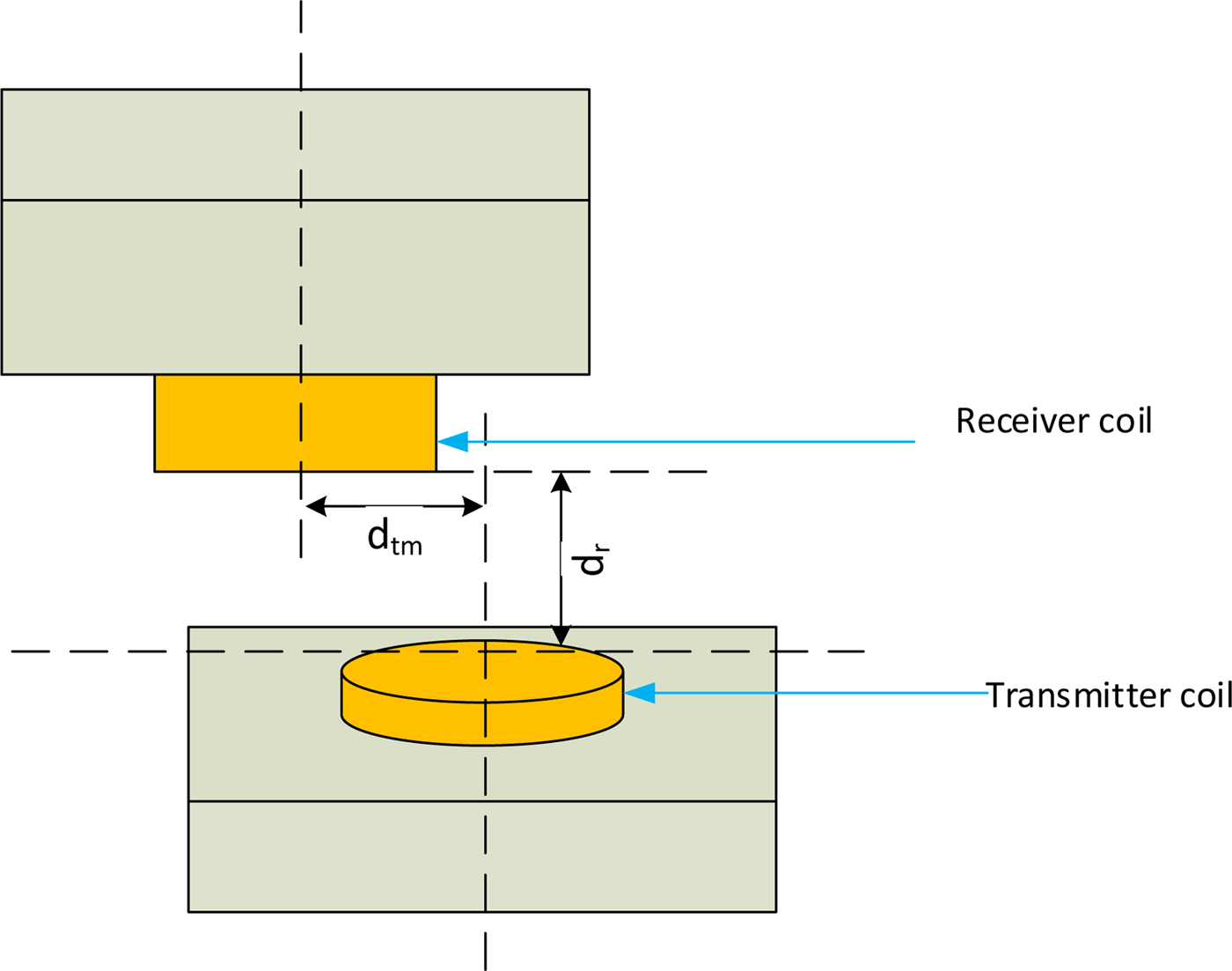
Fig. 7. Basic configuration of translational misalignment between the coils.
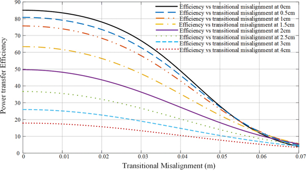
Figure 8 shows the plotted power efficiency against a changing transition misalignment, d tm going from 0 to 7 cm at a varying distance of separation, d r, ranging from 0 to 4 cm. The simulations suggest high coupling at smaller d tm and d r distances and tend to zero as the coils are further separated as a result of a lowered coupling factor. The analysis suggests that a misalignment up to about 3 cm will not affect the performance of the proposed system (since PTE is well above 10%) as this is usually the normal sitting position of the user.
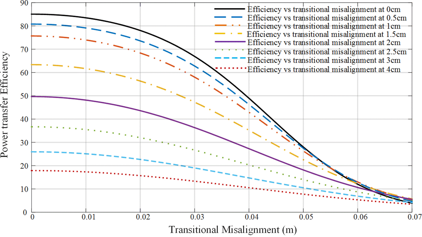
Fig. 8. Power transfer efficiency at different misalignment positions shown in Fig. 7 by varying the distance between the transmitter and receiver coils in x and y directions.
V. EXPERIMENTAL PROCEDURE
The amount of power transferred with the system varied depending on the load resistance connected to the receiver. Moreover, a range of dummy loads was tested to understand the battery's impedance since the battery's charging and discharging activity is a chemical process.
A) WPT efficiency
The first test procedure is to carry out measurements to determine the power efficiency of the WPT system. The connection was done between the wireless power system consisting of a dummy load, a receiver and transmitter. The methods, steps, and relevant documentation are described in [66]. These steps serve as a precaution against wrong connections which could lead to components blowing up.
B) Three-Element Array
The next step was to replace the single coil with an array of three overlapping coils; i.e. a 3 × 1 array. The coils overlap each other to achieve uniform distribution of the magnetic field, without fields canceling each other [Reference van Wageningen and Staring39]. The 3-coil array is the 760308106 wireless charging coil from Wurth Electronic made of ferrite core material. The middle coil has an inductance of 11.5 and 12.5 µH for the side coils. The coils were connected in parallel to the transmitter and tested with the receiver without the battery, as described in Fig. 9.
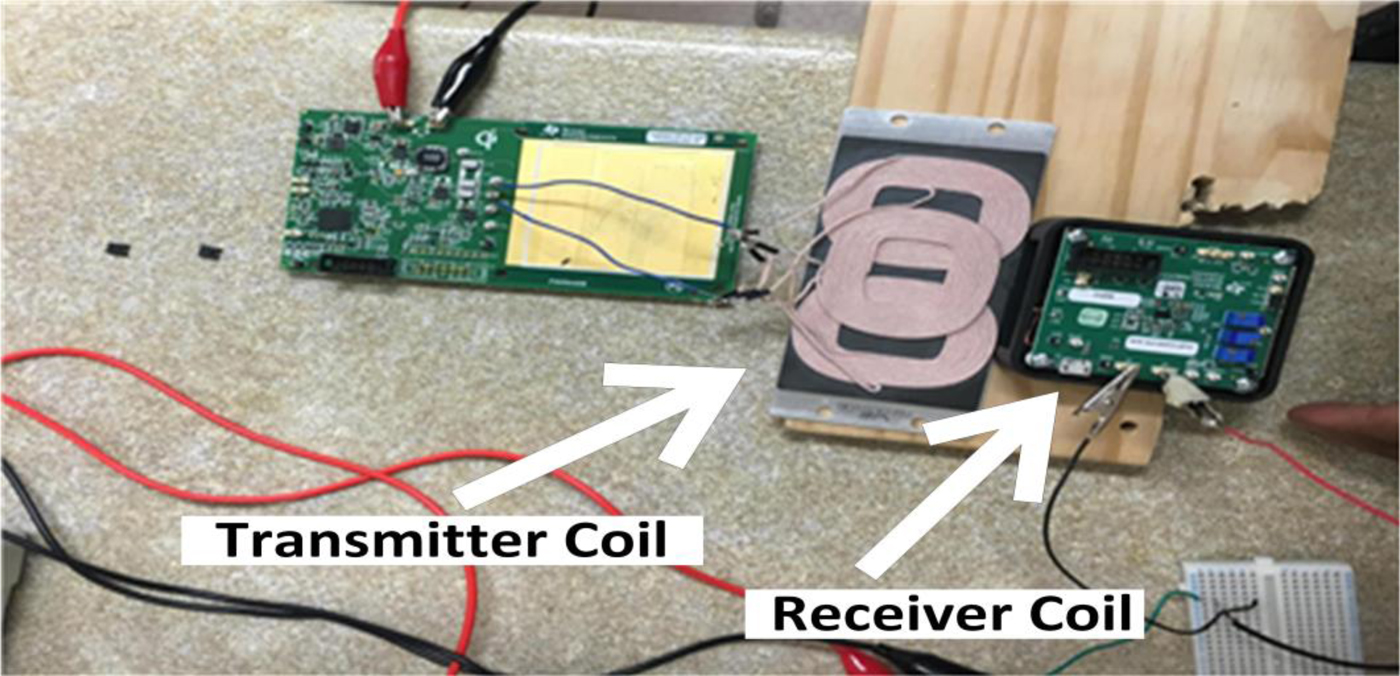
Fig. 9. Single transmitter coil replaced by the 3 × 1 array.
C) 3 × 3 Coil array
In this set-up a couple of rows were added to the 3 × 1 array (as described above) to increase the free positioning range on the backrest. Only the primary coils next to the receiver activated the power transfer process. This coil arrangement was made of three single 3 × 1 coil array resulting in a 3 × 3 coil arrangement array as described in Fig. 10.
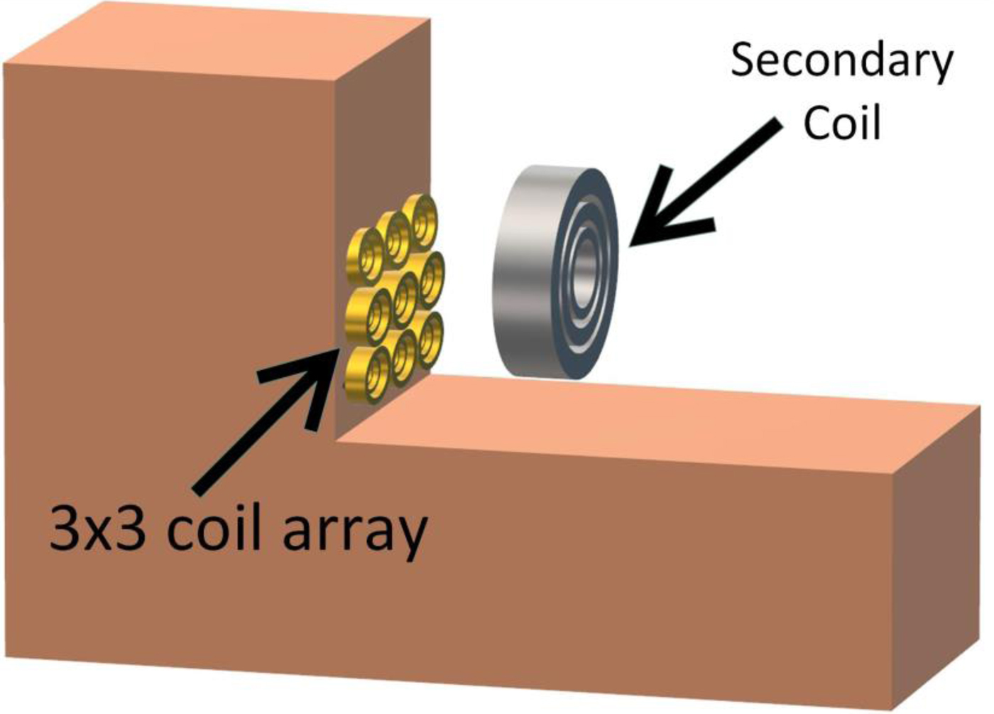
Fig. 10. Model illustrating the primary coil arrangement in the backrest.
VI. EXPERIMENTAL RESULTS
A) WPT efficiency measurement
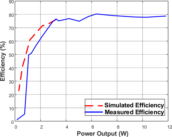
The wireless PTE of the system was calculated by measuring the input power at the transmitter and the output power at the receiver as expressed by:  $\eta = P_{RX}/P_{TX}\; \; 100\; \%, \; $. where η is the efficiency, P RX is the output power in watts and P TX is the input power in watts. The efficiency of the system went up to 80% and decreased as the load resistance increased.
Figure 11 shows the efficiency plot of the simulated and measured device. From this plot we are certain the WPT system works properly.
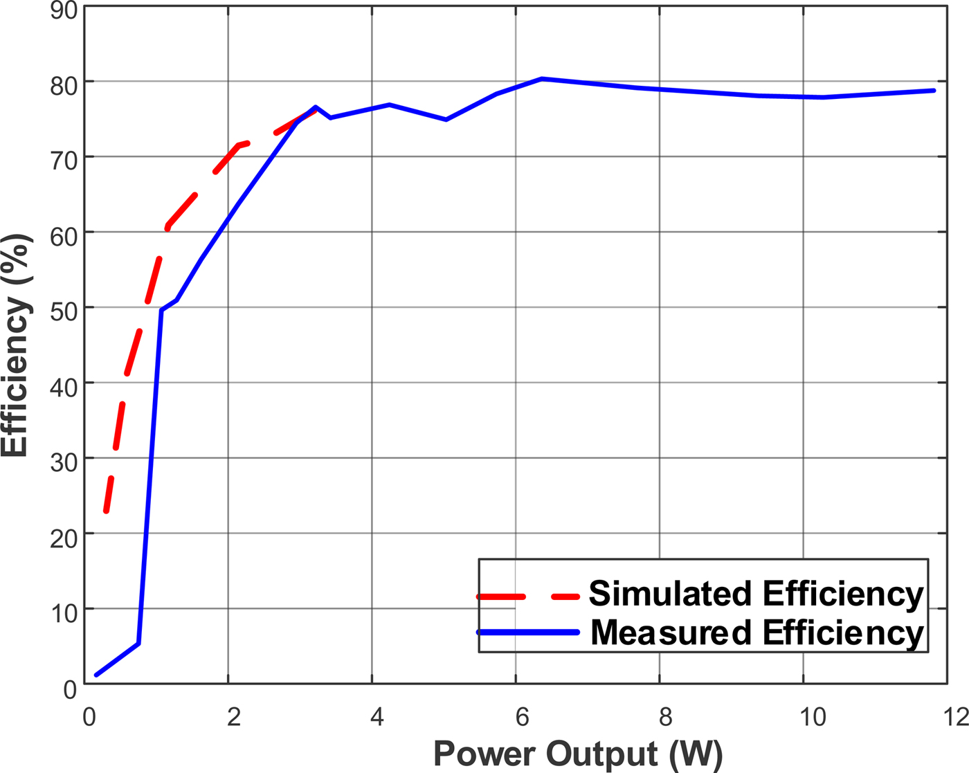
Fig. 11. Measured and simulated efficiency.
B) Power measurement
An open circuit test was done to estimate the batteries SOC, which is the maximum possible charge inside a battery at any one time. It mainly involves measuring the two terminals of a battery in open-circuit as described in [Reference Weng, Sun and Peng72] to obtain the voltage per cell. The battery was charged using an industrial charger and results from this were compared to the charging process done by the wireless power system, shown in Table 5, Fig. 12.
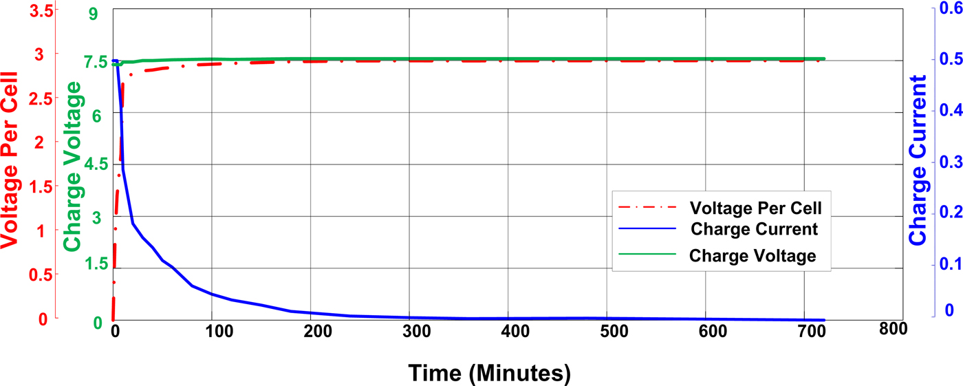
Fig. 12. Open-circuit measurements using WPT system.
Table 5. Open-circuit measurement using industrial charger.

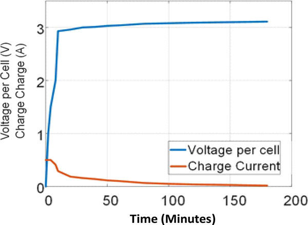
When the battery starts to charge, the voltage starts to rise quickly while the current is constant and then when charging progresses towards saturation, the current starts to drop while the voltage remains constant until terminated at stage 3. Meanwhile the charge capacity increases as shown in Fig. 13.

Fig. 13. Voltage-current curve of wireless power system and battery pack.
C) Discharge testing
It was observed the custom-made battery pack was able to regulate the current going into it. This safety feature was necessary as the battery was used to power a wearable and textile-based commercial product. This led to the significant drop of charge current as compared to the charger which employs a voltage regulator circuitry.
The WPT system cannot raise the voltage per cell higher as the charge current becomes too low resulting in lower saturation which can led to a lower discharge time of 2.5 h compared to 5 h seen when the battery reaches a higher capacity from the use of an industrial charger. Table 6 shows the voltage discharged after 3 hours when charged with the original charger and WPT system.
Table 6. Discharge result of battery.
D) Alignment testing
One of the main issues of concern is the systems flexibility particularly relating to alignment. Coupling should occur at any part of the system regardless of the sitting position. A possible solution is the use of an array of coils at the transmitter. The single transmitter coil was replaced by a 3-coil array as shown in Fig. 14, Table 7.
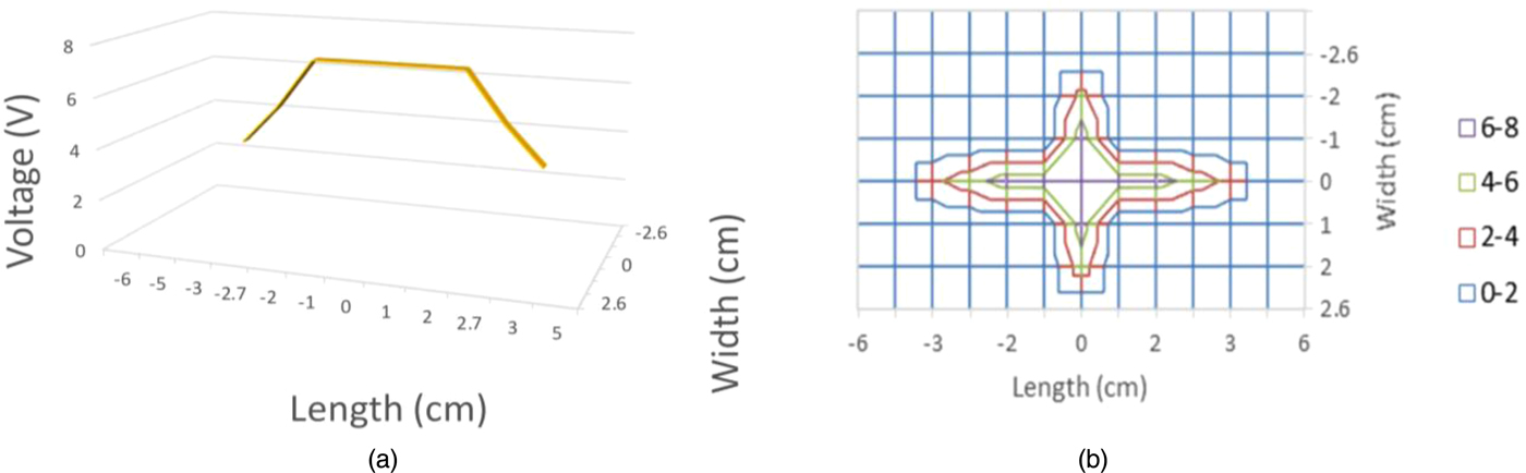
Fig. 14. Measured induced voltage in the secondary coil for the 3 × 1 array. (a) 3D representation, (b) contour plot representation.
Table 7. Alignment results.
VII. 3 × 3 COIL ARRAY IMPLEMENTATION
The voltage induced at the secondary coil using a 3 × 3 primary coil array was compared to that of a primary 3 × 1 coil array as shown in Figs 14 and 16, this was done to determine the dependence of the flux linkage. The primary coil array was connected in such a way to have an approximate inductance value of 10 uH as specified in [66]. The inner diameter and outer diameter of a single coil element within the array was 44.8 and 15.5 mm, respectively. It has 13 turns and a wire diameter of 1.19 mm. The gap between coils within the array was 1.85 mm and a single 3 × 1 array (3 elements) has a dimension of 94.7 mm × 53.35 mm while the complete 3 × 3 array (9 elements) is 94.7 mm × 162 mm.
The 3 × 3 array was found to have an increased coverage area of 187 cm2 from that of 28.62 cm2. Figure 14(b) shows the coverage area as a function of voltage recorded for the 3 × 1 array, the concentration, and charge area is seen to have increased in Fig. 16(b). The induced voltage at the receiver was measured by moving the coil center at grid intervals of 17 cm × 11 cm and spaced at 1 cm apart. A similar technique was used in [Reference Achterberg, Lomonova and de Boeij73]. Fig. 15 shows the coil arrangement under the charge area.
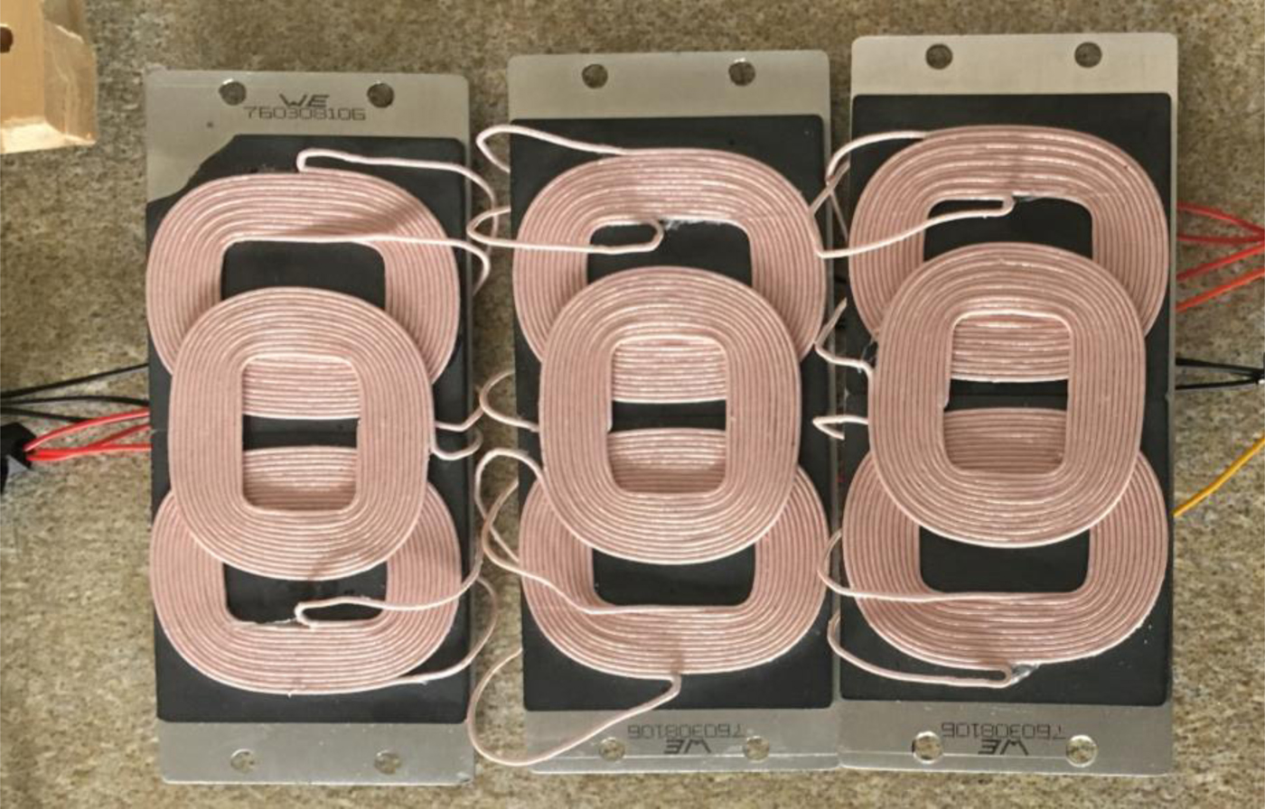
Fig. 15. The 3 × 3 coil array structure.
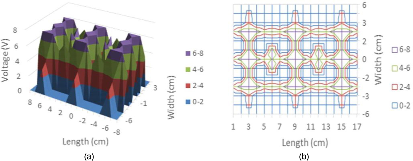
Fig. 16. Measured induced voltage in the secondary coil for the 3 × 3 array. (a) 3D representation, (b) contour plot. These plots indicate the considerably larger area for the WPT coverage when the 3 × 3 array of coils is used.
High and low peaks for the induced voltage can be observed in Fig. 16. The presence of low peaks indicates a low charge area due to the fact that the coil array elements do not completely overlap each other or are not completely close enough to ensure uniform coverage. Thus, improvements in the transfer efficiency could be possible by using a more compact array.
VIII. CONCLUSION AND FUTURE WORK
A WPT system was designed for a novel wearable heating system that provides warmth to its user. The wireless system consists of an array of coils at the transmitter and a single coil receiver that powers polymer resistors that generate heat when driven by applied current. This provides comfort and heat therapy for the wearer of the belt. The flux distribution was also investigated among two array configurations by moving the receiver across the array surfaces and recording the induced voltage. This helped determine the alignment conditions of the set of the arrays to achieve a considerable area of operation. Results in the paper demonstrated that a significantly increased charge area was made possible by the employed 3 × 3 coil array. Further improvements for the system can be made by designing an accompanying voltage regulator integrated circuit such as LM317 (variable regulator) or any fixed regulator such as LM7808 or LM7812 for better output voltage stability.
ACKNOWLEDGEMENT
This work was supported in part by the Horizon 2020 European Project CSA-EU (709372) and Scottish Enterprise. The authors would like to indicate that the work is only the authors views and that H2020 is not responsible for any information contained in the paper. The authors would also like to acknowledge the financial support of the UK Engineering & Physical Sciences Research Council (EPSRC) through the programme grant entitled Sonopill (EP/K034537/2). This work was partially supported by the H2020-MSCA-IF-2018 grant #840854 ViSionRF.
 Qassim S. Abdullahi was born in Jeddah, Saudi Arabia. He received MEng with distinction in electrical and electronics engineering from Heriot-Watt University, Edinburgh, UK in the summer of 2018. He is currently pursuing his Ph.D. in electrical engineering. His research area includes compact wearable antennas, frequency selective surface, metamaterials, wearable antennas, and wireless power transfer.
 Rahil Joshi was born in Satna, MP, India, and received BE (Hons) in electronics and communications engineering in 2014 from Birla Institute of Technology and Science, Pilani-Dubai Campus. In 2015, he received MSc in communication and signal processing engineering from Newcastle University, UK. He is currently working towards his Ph.D. in the Institute of Sensors, Signals, and Systems from Heriot-Watt University, UK. His research interests are in areas of compact antennas, planar antennas, wearable antennas, software-defined radio, and wireless power transfer.
 Symon K. Podilchak received BASc in engineering science from the University of Toronto, Ontario, Canada, in 2005. While studying at Queen’s University in Kingston, Ontario, Canada he received an MASc and a Ph.D. in electrical engineering in 2008 and 2013, respectively, and he was honored with an Outstanding Dissertation Award for his Ph.D. from the same institution. From 2013 to 2015, Symon was an assistant professor at Queen's University. He then joined Heriot-Watt University, Edinburgh, Scotland, UK in 2015 as an assistant professor and became an associate professor in 2017. Currently his research is supported by a H2020 Marie Skłodowska-Curie European Research Fellowship and cross-appointed at Edinburgh University, Scotland.
Dr. Podilchak is a registered professional engineer (P.Eng.) and has had industrial experience as a computer programmer, and has designed 24 and 77 GHz automotive radar systems with Samsung and Magna Electronics. Recent industry experience also includes the design of highfrequency surface-wave radar systems, professional software design and implementation for measurements in anechoic chambers for the Canadian Department of National Defence and the SLOWPOKE Nuclear Reactor Facility. Dr. Podilchak has also designed new compact multiple-input–multiple-output (MIMO) antennas for wideband military communications, highly compact circularly polarized antennas for microsatellites with COM DEV International, as well as new wireless power transmission systems for Samsung. His research interests include surface waves, leaky-wave antennas, metasurfaces, UWB antennas, phased arrays, and CMOS integrated circuits.
Dr. Podilchak has been the recipient of many best paper awards and scholarships; most notably Research Fellowships from the IEEE Antennas and Propagation Society, as well as, the IEEE Microwave Theory and Techniques Society. He also received a Postgraduate Fellowship from the Natural Sciences and Engineering Research Council of Canada (NSERC) and four Young Scientist Awards from the International Union of Radio Science (URSI). In 2011 and 2013 he received student paper awards at the IEEE International Symposium on Antennas and Propagation, and in 2012, the best paper prize for Antenna Design at the European Conference on Antennas and Propagation for his work on CubeSat antennas, and in 2016, received The European Microwave Prize for his research on surface waves and leaky-wave antennas. In 2017 and 2019, Dr. Podilchak was bestowed a Visiting Professorship Award at Sapienza University in Rome. In 2014, the IEEE Antennas and Propagation Society recognized Dr. Podilchak as an Outstanding Reviewer for the IEEE Transactions on Antennas and Propagation. Dr. Podilchak was also the founder and first chairman of the IEEE Antennas and Propagation Society and the IEEE Microwave Theory and Techniques Society, Joint Chapter of the IEEE Kingston Section in Canada as well as Scotland. In recognition of these services, the IEEE presented Dr. Podilchak with an Outstanding Volunteer Award in May 2015. Currently he also serves as a lecturer for The European School of Antennas and is an associate editor to the journal IET Electronic Letters.
 Sadeque Reza Khan received BSc in electronics and telecommunication engineering from the University of Liberal Arts Bangladesh, Dhaka, Bangladesh, in 2010 and an MTech in VLSI design from the National Institute of Technology, Mangalore, Karnataka, India, in 2014. He is currently pursuing Ph.D. in electrical engineering at Heriot-Watt University, Edinburgh, UK.
 Dr. Meixuan Chen holds a Ph.D. in textiles, awarded by the School of Textiles and Design, Heriot-Watt University in 2017. Her Ph.D. research began with practical experiments in designing interactive textiles and then investigated how this design aesthetics can affect viewers’ emotions and personal preferences. Prior to Ph.D. studies, she went on to be trained as a textile designer specializing in knitted textiles, at Central Saint Martin’s College of Arts and Design in London, and had completed a Bachelor degree in textiles design and a Master degree in design for Textiles Futures. She has been working as a research associate in School of Textiles and Design at Heriot-Watt University. The main focus of her role is to provide specialist support and conduct research projects in textile design and materials engineering.
Dr. Jean Rooney Bio not available at the time of publication.
Dr. John Rooney Bio not available at the time of publication.
 Dr. Danmei Sun is an associate professor and has over 25 years work experience in textile materials and engineering both practical and theoretical. Her research interests include smart polymers and fibres, engineering design 2D/3D textile structures for technical textiles and performance clothing, thermal regulated textiles and clothing by embedding thermal chemicals, finite element modelling and prediction or textile properties and environmental friendly finishing. Her research has been supported by various funding bodies such as UK Dstl/MoD, Oil and Gas Innovation Centre, Scottish Funding Council, as well as company partners such as Harris Tweed, Iron and Ocean Ltd. etc.
 Marc P. Y. Desmulliez (SM’87) received a Ph.D. in optoelectronics from Heriot-Watt University, Edinburgh, UK, in 1995. He is currently a professor of microsystems engineering with Heriot-Watt University, where he leads the Multimodal Sensing and Micro-Manipulation Research Group.
 Dr. Apostolos Georgiadis was born in Thessaloniki, Greece. He received BS in physics and an MS in telecommunications from the Aristotle University of Thessaloniki, Greece, in 1993 and 1996, respectively. He received Ph.D. in electrical engineering from the University of Massachusetts, Amherst, in 2002. In 1995, he spent a semester with Radio Antenna Communications (RAC), Milan Italy, working on Yagi antennas for UHF applications. In the summer of 2000, he was with Telaxis Communications, South Deerfield, MA, USA, where he assisted in the design and testing of a pillbox antenna for LMDS applications.. In 2002 he joined Global Communications Devices (GCD), North Andover, MA, USA, as a systems engineer and worked on CMOS transceivers for wireless network applications. In June 2003, he joined Bermai, Inc., Minnetonka, MN, USA, as an RF/Analog Systems Architect. In 2005 he joined the University of Cantabria, Spain, as a Juan de la Cierva Fellow researcher. In 2006 he was a consultant for Bitwave Semiconductor, Lowell, MA, USA. In addition he collaborated with ACORDE S.A., Santander, Spain, in the design of integrated CMOS VCOs for ultra-wideband (UWB) applications. In March 2007 he joined CTTC as a senior research associate in the area of Communications Subsystems. In 2013–2016 he was a group leader of the Microwave Systems and Nanotechnology Department of CTTC. In July 2016 he joined Heriot-Watt University, Edinburgh as an associate professor. In 1996, Dr. Georgiadis received a Fulbright Scholarship for graduate studies at the University of Massachusetts, Amherst. He received the Outstanding Teaching Assistant Award from the University of Massachusetts, Amherst, in 1997 and 1998. He also was the recipient of the Eugene M. Isenberg Award from the Isenberg School of Management, University of Massachusetts, Amherst, in 1999 and 2000. He was the general chair of 2011 IEEE RFID-TA Conference and general co-chair of the 2011 IEEE MTT-S IMWS on Millimeter Wave Integration Technologies. He was the chairman of COST Action IC0803 RF/Microwave communication subsystems for emerging wireless technologies (RFCSET). He is vice-chair of COST Action IC1301 Wireless Power Transmission for Sustainable Electronics (WiPE). He was the coordinator of Marie Curie Industry-Academia Pathways and Partnerships (IAPP) project Symbiotic Wireless Autonomous Powered system (SWAP). He is member of the IEEE MTT-S TC-24 RFID Technologies (past chair) and member of IEEE MTT-S TC-26 Wireless Energy Transfer and Conversion. He serves as an associate editor of the IEEE Journal on RFID. He has been associate editor of the IEEE Microwave and Wireless Components Letters, the IET Microwaves Antennas and Propagation and the IEEE RFID Virtual Journal. He co-founded and was editor-in-chief of the Cambridge Wireless Power Transfer Journal. He was a distinguished lecturer of IEEE Council on RFID. He is URSI fellow and chair of URSI Commission D: Electronics and Photonics. He is IEEE senior member. His research interests include energy harvesting and wireless power transmission, RFID technology, active antennas and phased array antennas, inkjet and 3D printed electronics, millimeter wave systems. He has published more than 200 papers in peer-reviewed journals and international conferences.
 Dr. Dimitris E. Anagnostou (S'98-M'05-SM'10) received the BSEE degree from the Democritus University of Thrace, Greece, in 2000, and the MSEE and Ph.D. from the University of New Mexico, Albuquerque, NM, USA, in 2002 and 2005, respectively. From 2005 to 2006, he was a postdoctoral fellow at the Georgia Tech, Atlanta, GA, USA. In 2007, he joined as assistant professor the SD School of Mines & Technology, SD, USA, where he received promotion as associate professor with tenure. In 2016, Dr. Anagnostou joined the Heriot-Watt University, Institute of Signals, Sensors and Systems (ISSS) where he is currently a MSCA IF fellow and associate professor. Dr. Anagnostou has also worked at the Kirtland AFB, NM, and at the Democritus University of Thrace, Greece.
Dr. Anagnostou has authored or co-authored more than 130 peer-reviewed papers (h-index: 21) and he holds two U.S. patents. His interests include electromagnetic devices (antennas, microwave circuits, reconfigurable RF electronics, RADAR, sensors, and wearable electronics) for space satellites, defense, assisted living, and consumer applications such as 5G, as well as phase-change materials (VO2), artificial neural networks, printable spacecraft, and security printing.
Dr. Anagnostou has received multiple prestigious awards, including the IEEE John D. Kraus Antenna Award, the DARPA Young Faculty Award by the U.S. Department of Defense, the ASEE Campus Star Award by the American Society for Engineering Education, the UNM Young Alumni Award, the SDSMT Honored Faculty Award (4 times), and many others. Most recently, he was awarded the H2020 Marie Skłodowska-Curie European Research Fellowship that currently supports his research. Many of his students have also been recognized with IEEE and university awards such as Engineering Prize award (HWU) and Best PhD Thesis award (SDSMT).
Dr. Anagnostou serves or has served as associate editor for the IEEE Transactions on Antennas and Propagation, the IET Microwaves, Antennas and Propagation, IEEE Access, and as guest editor for the IEEE Antennas and Wireless Propagation Letters (two special issues), the Hindawi Intl’ Journal of Antennas and Propagation (two special issues), and the MDPI Technologies (one special issue). He is a member of the IEEE-APS Educational Committee, a member of the Technical Program Committee (TPC) and session chair for IEEE-APS and EuCAP Intl’ Symposia, and a reviewer for international journals such as Nature and IEEE Transactions. He is a member of Eta Kappa Nu (HKN) Honor Society, ASEE, and a professional engineer (PE) of the Technical Chamber of Greece (TEE).


 Open access