


1. Introduction
Interactive robots, such as exoskeletons and rehabilitation robots, require good abilities, such as the sensitive perception of interaction force and efficient movement performance, to interact with humans or unstructured environments safely and efficiently. There are many ways to obtain contact forces to realize reliable interactive performance, such as calculating contact torque by using torque sensors at joint of robots [Reference Tsetserukou and Tachi1], estimating contact torque by detecting electric current in driving motors [Reference Bertoluzzo, Buja and Menis2], and calculating contact torque by measuring deflections of elastic components embedded in robot joints [Reference Sunkyum and Chung3]. Compared with two former methods, elastic components can improve the safety of interactions because intrinsic compliance is implanted in the robot’s body. In addition, using elastic components has many advantages, such as stable force control, buffering ability, low cost, and high reliability [Reference Ham, Sugar, Vanderborght, Hollander and Lefeber4]. As a result, compliant actuators using elastic components have attracted increasing attentions, especially in robotics in unstructured environments, such as rehabilitation robots [Reference DeBoon, Nokleby, Delfa and Rossa5], prostheses [Reference Au, Herr, Weber and Martinez-Villalpando6], exoskeletons [Reference Karavas, Ajoudani, Tsagarakis, Saglia, Bicchi and Caldwell7], and walking robots [Reference Van Ham, Vanderborght, Van Damme, Verrelst and Lefeber8]. A representative compliant actuator is the series elastic actuator (SEA) [Reference Pratt and Williamson9], which typically uses a linear spring as the elastic component to achieve the required motion and stiffness characteristics. Next, SEAs with linear springs developed rapidly [Reference Kong, Bae and Tomizuka10–Reference Pei, Han, Zallek, Liu, Yang and Hsiao-Wecksler16]. Owing to the constant stiffness of linear spring, there is a trade-off between the torque resolution and control bandwidth. To be specific, high stiffness increases control bandwidth and position tracking precision but reduces torque/force resolution and safety performance. Low stiffness increases torque/force resolution and shock absorption and improves safety performance at the cost of system control bandwidth [Reference Robinson17–Reference Paine, Oh and Sentis19].
To address the limitation of SEA, variable stiffness actuator (VSA) was proposed and developed rapidly [Reference Tsagarakis, Sardellitti and Caldwell20–Reference Liu, Misgeld, Pomprapa and Leonhardt33]. However, most VSAs are equipped with two actuators (usually motors) to actively adjust the stiffness and equilibrium position independently, which leads to bulky and complex structures and causes additional power consumption. Moreover, from the perspective of increasing torque resolution and bandwidth, completely decoupling of load and stiffness in VSAs results in some useless load-stiffness mapping space where stiffness is high under small loads, and stiffness is low under large loads [Reference Ju, Gong, Qi, Kang, Dai and Song34]. In addition, the speed of adjusting the stiffness is usually limited by the drive response and control efficiency, which reduces the interaction safety. To overcome limitations of VSAs, a new concept of compliant actuators was proposed, named nonlinear stiffness elastic actuator (NSEA), which has a purely passive nonlinear spring and omits the active stiffness tuning motor at the cost of embedding a single load-deflection profile. The stiffness and equilibrium position of the NSEA are coupled, and stiffness is adaptatively adjusted by load [Reference Song, Lan and Dai35, Reference Hu, Song and Ma36]. The NSEA can achieve the high torque/force resolution in the low stiffness range and the high bandwidth in the high stiffness range; therefore, it can improve the performance of compliant actuators and provide good force sensing ability and control bandwidth [Reference Zhao, Song, Ma and Dai37].
The key to design a NSEA is designing a mechanism with nonlinear stiffness characteristic. Many researchers used assembled mechanical solutions to achieve nonlinear stiffness. Thorson and Caldwell [Reference Thorson and Caldwell38] designed an NSEA that uses a hypocycloid mechanism to stretch a linear tension spring in a nonlinear manner. Although it achieves a high dynamic performance, it has a low power-to-weight ratio. Zhang et al. [Reference Zhang, Guo, Wu, Gao, Kou and Eriksson39] designed a flexure revolute joint with nonlinear stiffness by substituting the stiff rocker as flexible material in crank-rocker mechanisms. Liu et al. [Reference Liu, Wang, Yang, Liu and Hao40] utilized a double-stage four-linkage mechanism to design a passive power-source-free stiffness-self-adjustable mechanism which can automatically adjust nonlinear stiffness in accordance with the magnitude of the payload. Although many designs achieved nonlinear stiffness, they are not suitable for those applications which need predefined nonlinear stiffness characteristic. To achieve predefined nonlinear stiffness characteristic, Migliore et al. [Reference Migliore, Brown and DeWeerth41] used cams, rollers, and linear spiral springs to design a translational nonlinear stiffness mechanism, which can produce specific load-deflection relationships. Shao et al. [Reference Shao, Zhang, Su and Ding42] designed a load-adaptative actuator with variable stiffness, in which a novel nonlinear spring mechanism with user-defined load-deflection behavior was designed by combining a cam mechanism with parabolic beams. For assembled mechanical solutions, assembly errors and frictions are inevitable issues, which can affect the performance of compliant actuators. In addition, the increment in part count is not conducive to simplify the mechanical system.
As common elastic components, compliant mechanisms with monolithic structures are widely used in precision engineering [Reference Rakuff and Cuttino43], flexible intelligent structures [Reference Lens, Kunz, von Stryk, Trommer and Karguth44], and interactive robots [Reference Lu and Kota45], owing to their advantages such as free assembly, no friction, energy storage, and high transmission efficiency. Compliant mechanism can be designed dexterously with respect to topology and dimension so that it can potentially achieve a given coupling nonlinear relationship between torque and deflection. However, the design of compliant mechanism with nonlinear stiffness is a big challenge. Tummala et al. [Reference Tummala, Frecker, Wissa and Hubbard46] designed a twist compliant mechanism with nonlinear stiffness, which is flexible in one direction but has high stiffness in the opposite direction. Hao [Reference Hao47] proposed a general framework for designing compliant mechanisms with nonlinear stiffness, including stiffness-softening and stiffness-hardening. Although above-mentioned compliant mechanisms exhibit nonlinear stiffness characteristics, they are unable to meet the needs of applications that require a specific nonlinear stiffness characteristic. To satisfy the constraint of a given nonlinear stiffness characteristic, Bilancia et al. [Reference Bilancia, Berselli and Palli48] used slender spline beams as basic elements to design a compliant mechanism; meanwhile, its shape was optimized using finite element analysis (FEA) in order to provide a user-defined torque-deflection relationship. Radaelli and Herder [Reference Radaelli and Herder49] used isogeometric analysis paradigm to carry out shape optimization of compliant beams for prescribed load–displacement response.
In our previous work, by optimizing the stiffness form through an interactive strategy [Reference Zhao, Song, Ma and Dai37], a compliant actuator with nonlinear stiffness based on cams and cantilever flexible beams was developed, which requires high accuracy of manufacturing and assembly [Reference Song, Lan and Dai35]. In this study, to improve the performance of [Reference Song, Lan and Dai35], a general design method of torsional compliant mechanism with given torque-deflection profile was proposed. Considering the complexity of flexible beams in proposed compliant mechanism, a theoretical method to describe the large deformation in flexible beam was established. Moreover, a flexible beam-based compliant mechanism was designed, and its theoretical model of stiffness was developed. Its dimensional parameters were designed according to given torque-deflection points. Finally, simulation and physical experiment of the designed compliant mechanism through three given torque-deflection points are conducted to show the effectiveness of the proposed method.
2. Stiffness of proposed torsional compliant mechanism
A SEA can transform force information to position information owing to embedded compliant elements between its motor system and load, which improves the accuracy and stability of the force control, as shown in Fig. 1(a). Different elastic structures have been adopted to act as compliant elements. However, few of them exhibit a nonlinear relationship between torque and deflection. Compliant mechanisms can perform nonlinear stiffness, which have attracted the interests of many researchers. Although nonlinear stiffness characteristics commonly exist in many compliant mechanisms, it is a big challenge to design a compliant mechanism with desired nonlinear stiffness characteristic.

Figure 1. Schematic diagram of SEA and proposed torsional compliant mechanism: (a) structure of SEA and (b) torsional compliant mechanism.
In this study, using flexible beams as basic elements, we proposed a compliant mechanism with the given nonlinear torque-deflection relationship, as shown in Fig. 1(b). A flexible beam is composed of N basic beam elements connected in series, and there are angles between adjacent basic beam elements. A flexible beam is shown as green ellipse in Fig. 1(b), and a basic beam element is shown as red ellipse in Fig. 1(b). To ensure the stability of the mechanism under loads, multiple same flexible beams were uniformly arranged. To be embed in the NSEA, three parts were included in the compliant mechanism: the inner ring, the outer ring, and the flexible beams between them, and two ends of flexible beam are rigidly connected with inner ring and outer ring, respectively.
The nonlinearity of the proposed compliant mechanism comes from the geometric nonlinearity of the flexible beams. To be specific, when the flexible beam deforms, all basic beam elements deflect so the angles between them varies. As a result, the directions of force applied on all basic beam elements vary, and the relationship between external torque and rotational deflection of the compliant mechanism varies nonlinearly. Considering the complexity of flexible beams in the compliant mechanism, by comprehensively comparing the advantages and disadvantages of various existing flexible beam analysis methods, including the chain algorithm [Reference Howell and Midha50], pseudo-rigid-body model [Reference Howell and Midha51], and topology optimization [Reference Sigmund52], a chain algorithm based on 2R pseudo-rigid-body model is used to describe the large deformation in flexible beams. Moreover, the stiffness characteristic model of the torsional compliant mechanism is established.
2.1. Chain algorithm based on 2R pseudo-rigid-body model
To realize the design of compliant mechanism with a given torque-deflection profile, a model that can describe the large deformation in flexible beams is necessary. Considering the configuration of proposed compliant mechanism, we combined the chain algorithm and 2R pseudo-rigid-body model to describe the deformation of the flexible beam.
For definiteness and without loss of generality, the shape of a flexible beam is as the dotted line in Fig. 2. One end of the flexible beam is fixed on the inner ring, and the other end is subjected to a concentrated force F from the outer ring. The states of a flexible beam before and after deflection are shown in Fig. 2. According to the traditional chain algorithm, every basic beam element can be treated as an element so the flexible beam is discretized into N elements, which are numbered from the fixed end. One basic beam element is shown as the red ellipse, which corresponds to red ellipse in Fig. 1(b). The 2R pseudo-rigid-body model is established within each basic beam element, which composed of three rigid rods connected by two equivalent torsion springs. As a result, a flexible beam contains 2N equivalent torsion springs, which are also numbered from the fixed end.
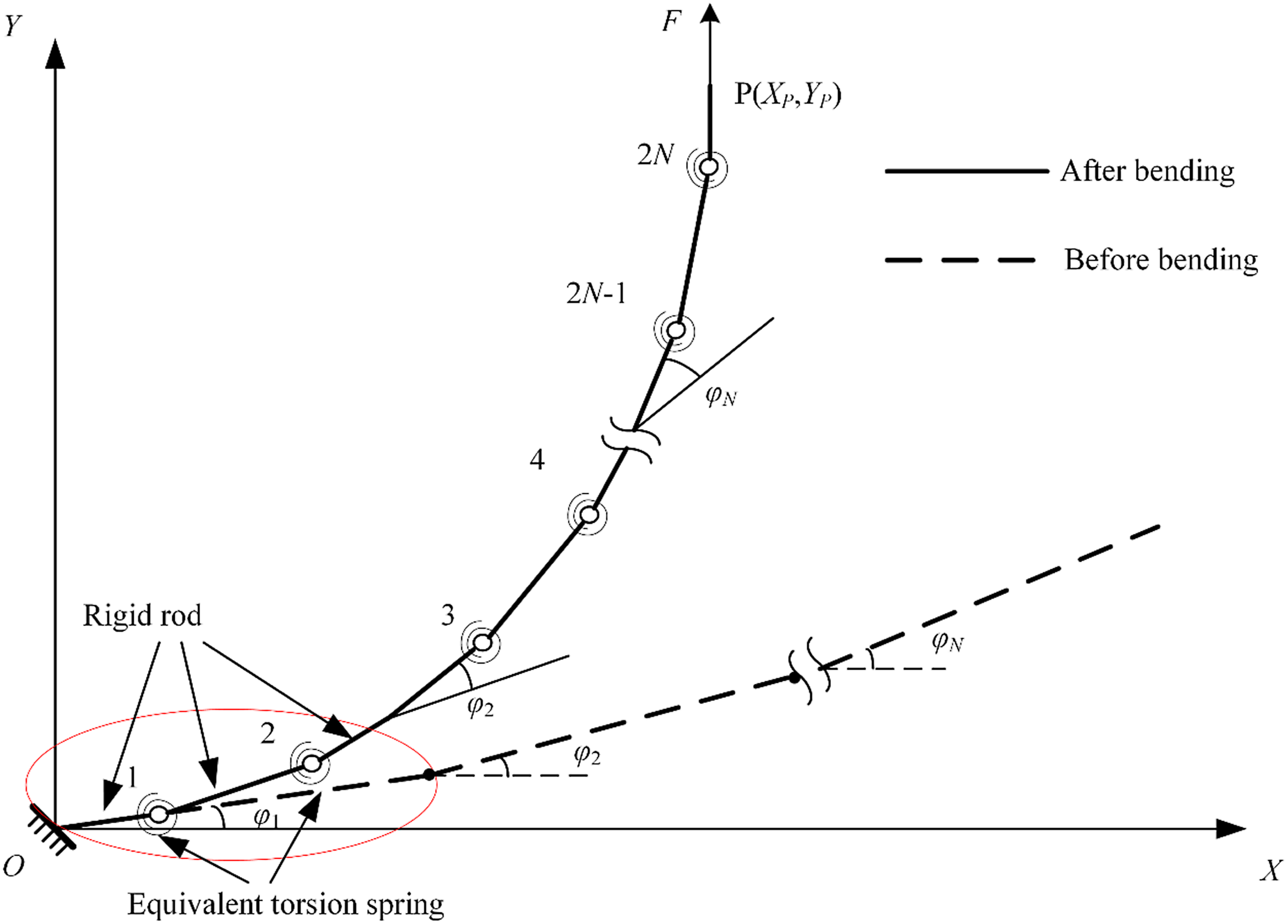
Figure 2. Schematic of a flexible beam.
In the chain algorithm based on 2R pseudo-rigid-body model, the deformation of the flexible beam can be evaluated only by calculating the deflection angle of each equivalent torsion spring, which is related to moment and stiffness on them. Firstly, a coordinate system XOY are established with the positive direction of the Y-axis conforming with the external force F, and the origin of the coordinate is set at the fixed end of the flexible beam, as shown in Fig. 2. Assuming that the angle between the nth basic beam element and the X-axis is $\varphi$
n
(n = 1, 2, …, N), the analysis and calculation are performed based on the static equilibrium state after the deformation of the compliant mechanism.
$\varphi$
n
(n = 1, 2, …, N), the analysis and calculation are performed based on the static equilibrium state after the deformation of the compliant mechanism.
To calculate the deformation of a flexible beam, we need to obtain the deformation of a basic beam element firstly. It is assumed that the end of the flexible beam moves slowly during the deformation process opposed to external force, ignoring the influence of the dynamic effect. Thus, the mechanism can be assumed to be statically balanced. A static analysis diagram of a basic beam element in the flexible beam is conducted, as shown in Fig. 3. Assuming the end of flexible beam connecting the outer ring is P and the reaction force is F. Firstly, we analyze the stress of the Nth basic beam element.

Figure 3. Static analysis diagram of a basic beam element.
Because in the chain algorithm model, the subsequent basic beam element is considered as a cantilever beam inserted at the end of the previous basic beam element, the balance equations of shearing force $\boldsymbol{F}'_{\!\!N}$
and bending moment
$\boldsymbol{F}'_{\!\!N}$
and bending moment $\boldsymbol{M}'_{\!\!N}$
in the front end of the Nth basic beam element can be written as follows:
$\boldsymbol{M}'_{\!\!N}$
in the front end of the Nth basic beam element can be written as follows:
 \begin{equation} \boldsymbol{F}^{\boldsymbol\prime}_{N}=\boldsymbol{F} \end{equation}
 \begin{equation} \boldsymbol{M}^{\boldsymbol\prime}_{N}=\boldsymbol{F}\cdot \left(X_{\mathrm{P}}-X_{N}\right) \end{equation}
where X P and X N are the abscissas of the point P and front end of the Nth basic beam element, respectively. Because the positive direction of the Y-axis is the same as the direction of the external force, it is convenient to calculate the force arm by using the abscissa difference. Similarly, the torques applied on the equivalent torsion springs in the Nth basic beam element are as follows:
 \begin{equation} \boldsymbol{T}_{2N}=\boldsymbol{F}\cdot \left(X_{\mathrm{P}}-x_{2N}\right) \end{equation}
 \begin{equation} \boldsymbol{T}_{2N-1}=\boldsymbol{F}\cdot \left(X_{\mathrm{P}}-x_{2N-1}\right) \end{equation}
where T 2N and T 2N−1 denote the torques applied on the (2N)th and (2N−1)th equivalent torsion springs, and x 2N and x 2N−1 denote the abscissas of the torsional centers of the (2N)th and (2N−1)th equivalent torsion springs.
Because the Nth basic beam element is fixed at the end of the (N−1)th basic beam element, the stress of the (N−1)th basic beam element can be obtained from the boundary conditions given by the Nth basic beam element:
 \begin{equation} \boldsymbol{F}^{\boldsymbol\prime}_{N-1}=\boldsymbol{F} \end{equation}
 \begin{equation} \boldsymbol{M}^{\boldsymbol\prime}_{N-1}=\boldsymbol{M}^{\boldsymbol\prime}_{N}+\boldsymbol{F}\cdot \left(X_{N}-X_{N-1}\right)=\boldsymbol{F}\cdot \left(X_{P}-X_{N-1}\right) \end{equation}
where $\boldsymbol{F}'_{\!\!N-1}$
and
$\boldsymbol{F}'_{\!\!N-1}$
and $\boldsymbol{M}'_{\!\!N-1}$
denote the shearing force and bending moment applied in the front end of the (N−1)th basic beam element, and X
N−1 is the abscissa of the front end of the (N−1)th basic beam element.
$\boldsymbol{M}'_{\!\!N-1}$
denote the shearing force and bending moment applied in the front end of the (N−1)th basic beam element, and X
N−1 is the abscissa of the front end of the (N−1)th basic beam element.
Similarly, the shearing force and bending moment in the front end of (N−2)th basic beam element can be deduced from the (N−1)th basic beam element. The above steps are repeated N times to obtain shearing forces and bending moments for all basic beam elements.
Similarly, the torques T i applied on the ith equivalent torsion springs are expressed as follows:
 \begin{equation} \boldsymbol{T}_{i}=\boldsymbol{F}\cdot \left(X_{\mathrm{P}}-x_{i}\right) \end{equation}
where x i denotes the abscissa of the torsional centers of the ith equivalent torsion springs and i = 1, 2, 3…, 2N.
To simplify the problems, it is assumed that the flexible beam has a constant cross section, and lengths of every basic beam element are l. According to the 2R pseudo-rigid-body model, in a flexible beam, each basic beam element is composed of two equivalent torsional springs with different stiffnesses and phases. According to the odd and even serial numbers, stiffnesses of equivalent torsion springs in the nth basic beam element can be obtained by:
 \begin{equation} \left[\begin{array}{l} K_{2{n}-1}\\[5pt] K_{2{n}} \end{array}\!\right]=\left[\begin{array}{l} K_{{\Theta\,} 2{n}-1}\\[5pt] K_{{\Theta\,} 2{n}} \end{array}\!\right]\cdot \frac{EI}{l} \end{equation}
Correspondingly, the relationship between the deflection angles, stiffnesses, and torques of equivalent torsion springs in the Nth basic beam element can be expressed as follows:
 \begin{equation} \left[\begin{array}{l} K_{2n-1}\\[5pt] K_{2n} \end{array}\!\right]=\left[\begin{array}{c@{\quad}c} \dfrac{1}{{\Theta }_{2n-1}} & 0\\[5pt] 0 & \dfrac{1}{{\Theta }_{2n}} \end{array}\!\right]\cdot \left[\begin{array}{l} \boldsymbol{T}_{2n-1}\\[5pt] \boldsymbol{T}_{2n} \end{array}\!\right] \end{equation}
where n is the number of basic beam element and n = 1, 2, 3…, N; K
2n−1 and K
2n
denote stiffnesses of equivalent torsion springs with odd and even numbers, respectively; $K_{\Theta 2n-1}$
and
$K_{\Theta 2n-1}$
and $K_{\Theta 2n}$
are the stiffness coefficients of the pseudo-rigid-body model, which can be found in literature [Reference Kimball and Tsai53]; E and I are the Young’s modulus and section moment of inertia of the flexible beam;
$K_{\Theta 2n}$
are the stiffness coefficients of the pseudo-rigid-body model, which can be found in literature [Reference Kimball and Tsai53]; E and I are the Young’s modulus and section moment of inertia of the flexible beam; $\Theta_{2n-1}$
and
$\Theta_{2n-1}$
and $\Theta_{2n}$
are the deflection angles of the equivalent torsion springs with odd and even numbers, respectively; T
2n−1 and T
2n
are torques applied on the torsion spring with odd and even numbers, respectively:
$\Theta_{2n}$
are the deflection angles of the equivalent torsion springs with odd and even numbers, respectively; T
2n−1 and T
2n
are torques applied on the torsion spring with odd and even numbers, respectively:
 \begin{equation} I=\frac{bh^{3}}{12} \end{equation}
where b and h denote the width and thickness of the flexible beam.
In chain algorithm based on 2R pseudo-rigid-body model, the deformation of flexible beam cam be expressed by deflection angles of equivalent torsion spring. From Eq. (8), we can get the values of K
2n−1 and K
2n
. By substituting the values of K
2n−1 and K
2n
into Eq. (9), we can get the deflection angles of the equivalent torsion springs, namely $\Theta$
2n−1 and
$\Theta$
2n−1 and $\Theta$
2n
on condition that
T
2N
and
T
2N−1 are known. To get
T
2N
and
T
2N−1, only the abscissas difference between P and rotational center of torsion springs, as revealed by Eq. (7). Therefore, we need to analyze the deformation of each basic beam element.
$\Theta$
2n
on condition that
T
2N
and
T
2N−1 are known. To get
T
2N
and
T
2N−1, only the abscissas difference between P and rotational center of torsion springs, as revealed by Eq. (7). Therefore, we need to analyze the deformation of each basic beam element.

Figure 4. Deformation of the first basic beam element.
In the chain algorithm, the angular displacements of each basic beam element in static equilibrium are superimposed consecutively from the fixed end, and the coordinates changes in the equivalent torsion spring in the first basic beam element are analyzed first. As shown in Fig. 4, the coordinates of the two equivalent torsion springs in the first basic beam element after deformation can be obtained as follows:
 \begin{equation} x_{1}=\gamma _{0}l\cdot \cos \varphi _{1} \end{equation}
 \begin{equation} y_{1}=\gamma _{0}l\cdot \sin \varphi _{1} \end{equation}
 \begin{equation} x_{2}=x_{1}+\gamma _{1}l\cdot \cos \!\left(\varphi _{1}+\Theta _{1}\right) \end{equation}
 \begin{equation} y_{2}=y_{1}+\gamma _{1}l\cdot \sin \!\left(\varphi _{1}+\Theta _{1}\right) \end{equation}
where, γ 0, γ 1, and γ 2 are the characteristic radial coefficients of the 2R pseudo-rigid-body model, and their values are γ 0 = 0.16, γ 1 = 0.66, and γ 2 = 0.18 [Reference Kimball and Tsai53].

Figure 5. Coordinate transformation of the Nth basic beam element.
After the deformation of the first basic beam element is obtained, the deformation of the second basic beam element can be analyzed. For the subsequent basic beam elements, their total displacement includes both its own elastic deformation and the rigid body rotation and translation superimposed on its previous basic beam elements, as shown in Fig. 5. Therefore, the coordinates of torsion springs in the nth basic beam element can be deduced by a recursive method as follows:
 \begin{equation} x_{2n-1}=x_{2n-2}+\gamma _{2}l\cdot \cos\!\left(\varphi _{n-1}+\sum _{i=1}^{2n-2}\Theta _{i}\right)+\gamma _{0}l\cdot \cos\!\left(\varphi _{n}+\sum _{i=1}^{2n-2}\Theta _{i}\right) \end{equation}
 \begin{equation} y_{2n-1}=y_{2n-2}+\gamma _{2}l\cdot \sin\!\left(\varphi _{n-1}+\sum _{i=1}^{2n-2}\Theta _{i}\right)+\gamma _{0}l\cdot \sin\!\left(\varphi _{n}+\sum _{i=1}^{2n-2}\Theta _{i}\right) \end{equation}
 \begin{equation} x_{2n}=x_{2n-1}+\gamma _{1}l\cdot \cos\!\left(\varphi _{n}+\sum _{i=1}^{2n-1}\Theta _{i}\right) \end{equation}
 \begin{equation} y_{2n}=y_{2n-1}+\gamma _{1}l\cdot \sin\!\left(\varphi _{n}+\sum _{i=1}^{2n-1}\Theta _{i}\right) \end{equation}
Assuming n = N, the coordinated of the last basic beam element can be obtained; subsequently, the recurrence formulas of (X N , Y N ), namely coordinates of the end point P(X P, Y P) of the flexible beam are given as follows:
 \begin{equation} X_{\mathrm{P}}=x_{2N}+\gamma _{2}l\cdot \cos\!\left(\varphi _{n}+\sum _{i=1}^{2N}\Theta _{i}\right) \end{equation}
 \begin{equation} Y_{\mathrm{P}}=y_{2N}+\gamma _{2}l\cdot \sin\!\left(\varphi _{n}+\sum _{i=1}^{2N}\Theta _{i}\right) \end{equation}
The coordinates of P0 (X P0, Y P0) which are the position of P before deformation are as follows:
 \begin{equation} X_{\mathrm{P}0}=l\cdot \sum _{i=1}^{N}\cos \varphi _{n} \end{equation}
 \begin{equation} Y_{\mathrm{P}0}=l\cdot \sum _{i=1}^{N}\sin \varphi _{n} \end{equation}
On condition that N, l, b, h, $\varphi$
i
are known, opposed to
F
, by combining Eqs. (7)–(20), the deflection angles Θ
i
of torsion springs can be solved. Moreover, by substituting values of Θ
i
into coordinates P(X
P, Y
P), the coordinates of P after deformation can be obtained. The deformation of flexible beam can be obtained by coordinates of P and P0.
$\varphi$
i
are known, opposed to
F
, by combining Eqs. (7)–(20), the deflection angles Θ
i
of torsion springs can be solved. Moreover, by substituting values of Θ
i
into coordinates P(X
P, Y
P), the coordinates of P after deformation can be obtained. The deformation of flexible beam can be obtained by coordinates of P and P0.
2.2. Stiffness model of torsional compliant mechanism
On the basis of deformation of flexible beam, the stiffness model of proposed torsional compliant mechanism can be further derived. In proposed compliant mechanism, torque is transformed between the inner ring and outer ring, while the flexible beams are deformed. Because the inner and outer rings are rigid and do not participate in the deformation, the overall stiffness characteristic of the compliant mechanism depends on the flexible beam. Therefore, we need to build the coupling relationship between deformation of flexible beam and rotational deflection of proposed compliant mechanism.
Considering the coupling relationship between force and motion, it is assumed that the inner ring of the mechanism is fixed, and the outer ring is subjected to an external torque. Therefore, the flexible beam is regarded as a cantilever beam with one end fixed on the inner ring and the other end rigidly connected to the outer ring, as shown in Fig. 1(b).
In practice, the end of the flexible beam, namely point P is subjected to reaction force F′ and a moment whose directions are unknown from the outer ring. To further simplify the stress of flexible beams, hinges are used to connect the flexible beams and the outer ring. Therefore, the flexible beams are only subjected to the reaction force F ′ and the friction of the hinges is ignored, as shown in Fig. 6.

Figure 6. Deformation of a flexible installed in the compliant mechanism.
Assuming that the angle between the direction of F ′ and F is Ψ F , a new coordinate system X′OY′ is established with the direction of positive direction of Y′ -axis conforms with F′ and its origin coincides with coordinate XOY. The equivalent torsion springs are numbered consecutively, and the deformation of each torsion spring is analyzed and calculated as follows:
 \begin{equation} \left\{\begin{array}{l} x^{\boldsymbol\prime}_{2n-1}=x^{\boldsymbol\prime}_{2n-2}+\gamma _{2}l\cdot \cos\!\left(\varphi ^{\boldsymbol\prime}_{n-1}+\sum _{i=1}^{2n-2}{\Theta }_{i}\right)+\gamma _{0}l\cdot \cos\!\left(\varphi ^{\boldsymbol\prime}_{n}+\sum _{i=1}^{2n-2}{\Theta }_{i}\right)\\[9pt] x^{\boldsymbol\prime}_{2n}=x^{\boldsymbol\prime}_{2n-1}+\gamma _{1}l\cdot \cos\!\left(\varphi ^{\boldsymbol\prime}_{n}+\sum _{i=1}^{2n-1}{\Theta }_{i}\right)\\[9pt] X^{\boldsymbol\prime}_{\mathrm{P}}=x^{\boldsymbol\prime}_{2N}+\gamma _{2}l\cdot \cos\!\left(\varphi ^{\boldsymbol\prime}_{n}+\sum _{i=1}^{2N}{\Theta }_{i}\right)\\[9pt] \boldsymbol{T}_{i}=\boldsymbol{F}^{\boldsymbol\prime}\cdot \left(X^{\boldsymbol\prime}_{P}-x^{\boldsymbol\prime}_{i}\right)\\[9pt] \left[\begin{array}{l} K_{2n-1}\\[9pt] K_{2n} \end{array}\right]=\left[\begin{array}{c@{\quad}c} \dfrac{1}{{\Theta }_{\mathrm{I}}} & 0\\[9pt] 0 & \dfrac{1}{{\Theta }_{\mathrm{II}}} \end{array}\!\right]\cdot \left[\begin{array}{l} \boldsymbol{T}_{2n-1}\\[9pt] \boldsymbol{T}_{2n} \end{array}\!\right]\\[-4pt] \\ \varphi ^{\boldsymbol\prime}_{n}=\varphi _{n}-\Psi _{F} \end{array}\right. \end{equation}
where $x'_{\!\!2n-1}$
,
$x'_{\!\!2n-1}$
, $x'_{\!\!2n}$
, and
$x'_{\!\!2n}$
, and $X'_{\!\!\textrm{P}}$
are the abscissas of the two equivalent torsion springs and point P in the coordinate system X′OY′
, respectively;
$X'_{\!\!\textrm{P}}$
are the abscissas of the two equivalent torsion springs and point P in the coordinate system X′OY′
, respectively; $\varphi'_{\!\!N}$
is the angle between the nth basic beam element and the X′
-axis before deformation.
$\varphi'_{\!\!N}$
is the angle between the nth basic beam element and the X′
-axis before deformation.
To establish the relationship between the external torque and deflection angle of the compliant mechanism, the constraint equation can be supplemented according to the geometric constraint that P is always located in the outer ring of the compliant mechanism, as shown in Fig. 7.

Figure 7. Geometric constraints of the flexible beam.
Thus, (X P0, Y P0) should satisfy following constraint:
 \begin{equation} R=\sqrt{\left(X_{\mathrm{P}0}+r\right)^{2}+{Y_{\mathrm{P}0}}^{2}} \end{equation}
where r is the diameter of inner ring, and R is the diameter of outer diameter.
Assuming that the deflection angle of the compliant mechanism is λ, when the compliant mechanism reaches static equilibrium state and the overall deflection angle of the mechanism is λ = Λ, the coordinate variations of P in coordinate system XOY can be obtained as follows:
 \begin{equation} {\Delta} x=R\cdot \cos\!\left(\Lambda +\Lambda _{0}\right)-R\cdot \cos \Lambda _{0} \end{equation}
 \begin{equation} {\Delta} y=R\cdot \sin\!\left(\Lambda +\Lambda _{0}\right)-R\cdot \sin \Lambda _{0} \end{equation}
where Δx and Δy are coordinates variations of P; Λ 0 is the angle of flexible beam before deformation relative to the X-axis, which can be calculated as follows:
 \begin{equation} \Lambda _{0}=\arctan \frac{Y_{\mathrm{P}0}}{X_{\mathrm{P}0}+r} \end{equation}
Therefore, the coordinates of P in the coordinate system XOY after deformation are as follows:
 \begin{equation} X_{\mathrm{P}}=X_{\mathrm{P}0}+{\Delta} x \end{equation}
 \begin{equation} Y_{\mathrm{P}}=Y_{\mathrm{P}0}+{\Delta} y \end{equation}
According to the coordinate transformation matrix, the coordinates of P in coordinate system X′OY′ can be obtained as:
 \begin{equation} \left[\begin{array}{l} X^{\boldsymbol\prime}_{\mathrm{P}}\\[5pt] Y^{\boldsymbol\prime}_{\mathrm{P}} \end{array}\right]=\left[\begin{array}{l@{\quad}l} \cos \psi _{F} & \sin \psi _{F}\\[5pt] -\!\sin \psi _{F} & \cos \psi _{F} \end{array}\right]\cdot \left[\begin{array}{l} X_{\mathrm{P}}\\[5pt] Y_{\mathrm{P}} \end{array}\right] \end{equation}
According to Eq. (23), we can derive the recurrence formula of the ordinates of torsion spring and point P in coordinate system X ′ OY ′ as follows:
 \begin{equation} \left\{\begin{array}{l} y^{\boldsymbol\prime}_{2n-1}=y^{\boldsymbol\prime}_{2n-2}+\gamma _{2}l\cdot \sin\!\left(\varphi ^{\boldsymbol\prime}_{n-1}+\sum _{i=1}^{2n-2}\Theta _{i}\right)+\gamma _{0}l\cdot \sin\!\left(\varphi ^{\boldsymbol\prime}_{n}+\sum _{i=1}^{2n-2}\Theta _{i}\right)\\[8pt] y^{\boldsymbol\prime}_{2n}=y^{\boldsymbol\prime}_{2n-1}+\gamma _{1}l\cdot \sin\!\left(\varphi ^{\boldsymbol\prime}_{n}+\sum _{i=1}^{2n-1}\Theta _{i}\right)\\[8pt] Y^{\boldsymbol\prime}_{\mathrm{P}}=y^{\boldsymbol\prime}_{2N}+\gamma _{2}l\cdot \sin\!\left(\varphi ^{\boldsymbol\prime}_{n}+\sum _{i=1}^{2N}\Theta _{i}\right) \end{array}\right. \end{equation}
where $y'_{\!\!2n-1}$
,
$y'_{\!\!2n-1}$
, $y'_{\!\!2n}$
, and
$y'_{\!\!2n}$
, and $Y'_{\!\!\textrm{P}}$
are the ordinates of the two equivalent torsion springs and point P in the coordinate system X′OY′
, respectively.
$Y'_{\!\!\textrm{P}}$
are the ordinates of the two equivalent torsion springs and point P in the coordinate system X′OY′
, respectively.
To realize the design of compliant mechanism with the given discrete torque-deflection points, the relationship between the reaction force F′ in the flexible beam and the external torque M on the compliant mechanism is established as follows:
 \begin{equation} \boldsymbol{M}=C\boldsymbol{F}\cos\!\left(\psi _{F}-\Lambda -\Lambda _{0}\right)R \end{equation}
where C is the number of flexible beams in a compliant mechanism.
By combining Eqs. (23)–(32), one can solve the stiffness of the proposed compliant mechanism, namely the relationship between external torque M and deflection angle Λ.
3. Design of compliant mechanisms with given torque-deflection points
The theoretical contents above explain the fundamental methods for designing a compliant mechanism with flexible beams to exhibit a given torque-deflection profile. But above formulation is on condition that many geometric parameters are known in advance. In practical designs, materials and some geometric parameters of the compliant mechanism should be determined firstly, including the number of flexible beams C, the number of basic beam element in a flexible beam N, the length of a basic beam element l, the width b, and thickness h of a flexible beam, diameter of inner ring r, and diameter of outer ring R. The angles $\varphi$
i
between basic beam elements and X-axis are considered. Considering that the design is based given torque-deflection points, we select the angles
$\varphi$
i
between basic beam elements and X-axis are considered. Considering that the design is based given torque-deflection points, we select the angles $\varphi$
i
between basic beam elements and X-axis as unknown variable. By solving the
$\varphi$
i
between basic beam elements and X-axis as unknown variable. By solving the $\varphi$
i,
the shape of compliant mechanism is uniquely determined.
$\varphi$
i,
the shape of compliant mechanism is uniquely determined.
The number of flexible beams C can be decided according to arrangement of flexible beams. The number of basic beam element in a flexible beam N is closely related with the solution of stiffness model of compliant mechanism. To obtain a unique solution, N should equal to the number of given torque-deflection points. The diameter r of the inner ring is usually related to the size of the connector of the NSEA and can be determined directly. The diameter R of the outer ring can be decided by the application scenario. As for the length of a basic beam element l, it should satisfy following constraint and determined empirically and preliminarily:
 \begin{equation} l\leq \frac{R-r}{N} \end{equation}
The overall width of the compliant mechanism should not exceed b 0. For hinged compliant mechanism, the width b of flexible beam is considered to ensure structural strength:
 \begin{equation} b\leq \frac{b_{0}}{2} \end{equation}
The cross-sectional dimension of the basic beam element, including b and h, directly affects the overall stiffness range of the compliant mechanism, which is reflected in the stiffness of the equivalent torsion spring in the 2R pseudo-rigid-body model. Therefore, it is necessary to verify whether the cross-sectional dimension of a basic beam element meets the requirements of the given torque-deflection characteristic. Here, we use a given torque-deflection point to solve one set of cross-sectional dimension and use FEA to carry out verification.
In summary, the parameter design process of the compliant mechanism is as follows:
-
1. According to the number of stiffness characteristic points, the number of basic beam elements N is first determined. Combined with the overall size limit, the value of the beam element length l is decided preliminarily.
-
2. One given discrete torque-deflection point is substituted into the stiffness model of compliant mechanism for an initial estimation of the cross-sectional moment of the flexible beam. According to the simulation results of FEA, the values of b and h on the basis of known cross-sectional moment are adjusted to satisfy the stiffness range of the compliant mechanism.
-
3. A chain algorithm based on the 2R pseudo-rigid-body model is established. The equilibrium equations corresponding to each torque-deflection point are written, and the equations are solved numerically to obtain the values of $\varphi _{i}$
. If an effective solution cannot be obtained, the dimension the cross section is adjusted and recalculated until a group of effective solutions meets the design objectives.
$\varphi _{i}$
. If an effective solution cannot be obtained, the dimension the cross section is adjusted and recalculated until a group of effective solutions meets the design objectives. -
4. Bending strength of the flexible beam is checked, and the three-dimensional model of the mechanism is established based on the parameters.

4. Simulations and experiments
4.1. Parameters of compliant mechanism
The proposed design method in this study is verified by designing a compliant mechanism with three given torque-deflection points. The given discrete torque-deflection points and comprehensive design objectives of the compliant mechanism are presented in Table I. To fabricate compliant mechanisms cheaply and conveniently, 3D printing technology was adopted, and the material was photosensitive resin.
Table I. Comprehensive design objectives of the compliant mechanism prototype.

According to design objectives, the final geometric dimensions are decided and listed in Table II. The 3D model based on the parameters in Table II was built as shown in Fig. 8(a), and its 3D-printed prototype is shown in Fig. 8(b).
Table II. Dimensional parameters of flexible beams.


Figure 8. Virtual and physical compliant mechanism: (a) 3D model of compliant mechanism and (b) 3D-printed prototype.
4.2. Simulation of the given torque-deflection profile
In the simulation process, simulation software was used to obtain the relationship between torque and rotational deflection angles. The flexible beam end connection was considered as an ideal hinge. The inner ring of compliant mechanism is fixed, and a rotation was applied on the outer ring. The external torque and rotational angle of the outer ring, namely the deflection angle of the mechanism, were exported and compared with three given torque-deflection points, as shown in Fig. 9.

Figure 9. Comparison of simulated results with given torque-deflection points.
The simulation results show that the designed compliant mechanism has a stiffness characteristic that passes through the three given points, and the errors in the simulation results at the three torque-deflection points were approximately 0.01 rad, 0.0002 rad, 0.0022 rad, respectively, which achieved the design objective. This indicates that the proposed design method for compliant mechanism with given stiffness characteristic has high accuracy and reliability. It should be noted that the proposed design method only analyzes the discrete stiffness characteristic points, and the obtained mechanism design scheme cannot guarantee the stiffness performance under other rotation angles or loads. However, by increasing the number of given torque-deflection points, we can improve the fineness of the stiffness performance of the compliant mechanism.
4.3. Fabricated prototype and experiments
The compliant mechanism was fabricated and embedded into a NSEA prototype. To verify the accuracy of the prototype of performing given torque-deflection points, an experimental setup was built as shown in Fig. 10. The external torque and deflection angle of compliant mechanism were measured by a torque sensor and an angle encoder, respectively. The external torque was applied on the compliant mechanism by fixing the outer ring of the compliant mechanism and actuating the inner ring. In the meanwhile, the outer ring is connected to the torque sensor. The deflection angle of compliant mechanism was measured by installing the static disk of angle encoder on the inner ring and installing the kinetic disk of angle encoder on the outer ring. The measured angle and torque were recorded using a STM32F103 control board and processed in a PC. The selected torque sensor has a display that can show the torque value with a resolution of up to 0.001 Nm.

Figure 10. Prototype of the NSEA with the designed compliant mechanism and experimental setup.

Figure 11. Comparison of simulation and experimental results of stiffness characteristics of the designed compliant mechanism.

Figure 12. Compliant mechanism with rolling bearings.

Figure 13. Torque-deflection characteristic of compliant mechanism prototype using rolling bearings.
Figure 11 shows the relationship between the deflection angle and external torque of the designed compliant mechanism, which were derived from the simulation and experiment. It can be observed that the overall stiffness obtained from the experiment has a similar shape but is larger than that obtained from the FEA. The error in experimental results increases with an increase in the deflection angle of the compliant mechanism, and the maximum error of the torque is approximately 15%. Several factors can influence the experimental error, such as manufacturing error, assembly error, measurement error, and friction. During the theoretical analysis and simulation process, the end hinge of the flexible beam was considered as an ideal hinge, and its friction was ignored. However, in the physical prototype experiment, friction existed in the hinges. The force acting on the end of the flexible beam was the pressure between the inner wall of the hinge hole and the surface of the connecting shaft. According to the solutions of the equations, with an increase in the deflection angle of the compliant mechanism, the value of the pressure also exhibits an increasing trend, which causes the friction resistance at the hinge to increase gradually, so that the overall torsional stiffness of the compliant mechanism increases. To solve this problem, rolling bearings were used in the hinges to reduce the friction and thus, the overall errors. A physical prototype was again constructed with bearings installed as Fig. 12, and the stiffness characteristics of the new prototype were evaluated again as shown in Fig. 13.
Figure 13 shows that after using rolling bearings to reduce the hinge friction, the errors of torque-deflection relationship of the prototype are reduced, which indicates that the friction at the hinge is one of the factors of inducing the torque-deflection error in the previous prototype. The maximum relative error at the given torque-deflection points is approximately 5.67%.
The results of the simulation and prototype experiment show that the proposed method of designing a torsional compliant mechanism for NSEA with the given discrete torque-deflection points is effective. For achieving a more refined design, the method of increasing the given torque-deflection points can be used. However, with an increase in the number of points, the number of basic beam elements increase, which results in an increase in the complexity of solving the equations and accumulation of errors step by step, and further calculation is required to obtain the results.
5. Conclusions
This study proposed a general design method of a torsional compliant mechanism for NSEA, which has the given discrete torque-deflection points. Series flexible beams were used to obtain the desired stiffness owing to the existence of geometric nonlinearity. The chain algorithm was combined with the 2R pseudo-rigid-body model to describe the deformation of the flexible beam. A stiffness model of the proposed compliant mechanism was established, and then the dimensional parameters were designed according to given discrete torque-deflection points. Considering using a flexible beam including three basic beam elements as an example, the feasibility of the design method was verified through simulation and prototype experiment. Moreover, to relieve the friction and improve the accuracy of the performance of the given torque-deflection profile, a modified compliant mechanism using rolling bearings in the end of the flexible beam was designed and simulation verified the improvement of rolling bearings on performance of the proposed compliant mechanism. This study provides a new idea for the design of compliant mechanisms with given stiffness characteristics, which can be used in precision engineering, flexible intelligent structures, and interactive robots.
Author contributions
Wenjie Ju built the model and prototype and wrote the article; Zhibin Song conceived and designed the research and funded the research; Bingwei Li improved the model, conducted experiments, and analyzed experimental data. Rongjie Kang improved the article; Songyuan Zhang also funded the study and revised the article.
Financial support
This work was supported by the National Natural Science Foundation of China (Project No. 51975401, 51875393 and 51721003) and Opening Project of State Key Laboratory of Robotics and System (Harbin Institute of Technology).
Conflicts of interest
The authors declare no conflicts of interest exist.
Ethical approval
Not applicable.


