


Introduction
Ferrites belong to a large class of metal oxides and have been a center of extensive study because of the simultaneous presence of electrical with magnetic properties inside the same material. Due to the low cost, shape versatility, wide frequency range (10–50 kHz), temperature and time stability, high resistivity, economical assembly, and large selection material, ferrites have an edge over other magnetic materials.[Reference Srivastava and Yadav1] At the nanoscale, ferrites show unique properties which are very much distinct from their identical parts present inside bulk. The change in properties of ferrite nanoparticles is due to significant structural changes, joint rearrangements of electrons because of the reduced dimensionality and the surface atoms dominance.[Reference Tsuji, Wada, Yamamoto, Sano and Tamaura2–Reference Rondinone, Samia and Zhang4] In all these years, enough work has been done over ferrite nanoparticles with quite attractive industrial and scientific applications like rotary transformers, telecommunication, magnetic memory cores, magnetic recording heads, and electrical appliances.[Reference Golman5]
Multiferroics are scientifically as well as technologically fascinating materials because of the cross coupling between their ferroic order states within a single material. Bismuth ferrite (BiFeO3), abbreviated as BFO, perhaps is an alone perovskite structure depicting not even strong ferroelectric but magnetic effect naturally at a normal room temperature.[Reference Catalan and Scott6] The perovskite frameworks are of vast importance in today's research field due to exhibiting magnetic effect, excellent multiferroic properties, and photocatalytic behavior. These characteristics are beneficial to various applications including nonvolatile memory devices,[Reference Zaleski7] photoelectrochemical solar cells,[Reference Borse, Joshi, Ji, Jang, Jeong, Kim and Lee8] capacitors having magneto-capacitive effects,[Reference Kimura, Goto, Shintani, Ishizaka, Arima and Tokura9] and nonlinear optics.[Reference Nippolainen, Kamshilin, Prokoev and Jaskelainen10] For enhancing the electromagnetic behavior and structural properties of BFO, the researchers have doped it with numerous elements. This improvement in various physical properties exhibits an opportunity for the implementation of co-doped BFO nanostructures in our industry and different medical fields.
Carbon, an abundantly found element in nature, is a significant element among others in its family. Graphene is a two-dimensional allotropic form of carbon comprised of a single atomic layer organized in the shape of a hexagon. Graphene being the thinnest material can easily cover approximately 0.052 nm2 area and also 0.77 mg/m2 denser.[Reference Roussak and Gesse11] In comparison with the steel, graphene is hundred times mechanically stronger but much lighter in weight.[Reference Lee, Wei, Kysar and Hone12] In recent years, the graphene charm has covered the whole industry and owing to its exceptional optical behavior,[Reference Falkovsky13] mechanical strength, and electromagnetic properties,[Reference Choi and Lee14] it is treated as a most valuable material not even for the electronic industry but also for optical media. Its potential uses are limitless ranging from unique kinds of malleable electronics which on one hand can be worn over clothes but can be folded easily to put into a pocket, hence resulting a complete fresh generation consisting of small flexible computers, highly productive solar cells, and ultra-fast smart phones. Chemically, multilayer graphene is prepared by peeling of flake graphite with a suitable oxidizing and reducing agents since the single sheet of graphene is unstable and is challenging to fabricate under normal conditions. Graphene nanohybrids are the simplest structures which can be easily prepared with the addition of a small amount of graphene into polymers or different kinds of metals.[Reference Mertens15] Graphene presence inside these nanohybrids not even makes them mechanically much stronger and conductive but also more heat resistive in comparison with their pure forms. The hybrid structures of graphene with different magnetic materials or ferrites play a vital role in many applications such as band-gap tuning, various types of sensors, dye-sorption, antimicrobial activity, oil spill pollution, photocatalysis, etc.[Reference Silva and Carabineiro16]
Photocatalysts, comprised of semiconductors, have been widely used for the removal of pollutants from air and water over last few decades.[Reference Asahi, Morikawa, Ohwaki, Aoki and Taga17–Reference Tonga, Ouyang, Bi, Umezawa, Oshikiri and Ye19] A good photocatalyst should have minimal electron–hole (charge carriers produced when light falls) recombination, promote efficient charge transfer, and should absorb a wide solar spectrum. Under these specifications, different oxides[Reference Meng, Hong, Arndt, Li, Zhi, Yang and Wu20, Reference Zhang, Shao, Mu, Huang, Zhang, Guo, Zhang and Liu21] and their composites[Reference Seh, Liu, Low, Zhang, Liu, Mlayah and Han22–Reference Kong, Chen, Ma, Yang, Liu and Huang24] have been reported for degrading the organic molecules under irradiation of ultraviolet (UV) light. TiO2 has been very important in the photocatalytic activity as it was the first discovered UV light driven photocatalytic material.[Reference Fujishima and Honda25] In TiO2, photo-generated electrons and holes recombine at a fast rate which in turn makes it an inefficient photocatalyst.[Reference Stengl, Popelkova and Vlaci26, Reference Liang, Wang, Casalongue, Chen and Dai27] Since, sunlight is accessible as an easy and sufficient cheap source of electromagnetic radiation whose major portion is comprised of visible light, the finest way of its usage is purification of water and for doing so we need to design a photocatalyst which can actively perform its duty under irradiation of solar light. Freshly, it has been explored that BFO is not even an important multiferroic magnetoelectric material but also stimulates effectively under solar light. BFO nanoparticles exhibit a significant photocatalytic activity due to highly stable crystal structure, a sufficient band-gap, and vast surface area.[Reference Gao, Chen, Yin, Dong, Ren, Yuan, Yu and Liu28] By fabricating smaller particles with large surfaces it is possible to break down the organic pollutants in a shorter time duration. The water degradation occurs due to the oxidation of organic molecules which results in carbon dioxide (CO2) and water (H2O); both are harmless to the living tissues. The effective separation within holes and electrons acts as a vital entity in the process of oxidation and also in photo-catalytic activity. If a photocatalyst fails to maintain a sufficient electron–hole separation then the charge carriers with in the photocatalyst will recombine and hence there will be no oxidation. Graphene hybrids with BFO provides an active way of increasing photocatalytic behavior by maintaining a sufficient separation within the photo-generated electron–hole pairs.[Reference An, Zhu, Wang, Song, Yang, Du and Tang29, Reference Li, Shen, Yang, Lei, Guan, Lin, Liu and Nan30] Single crystalline perovskite BFO nanocubes were synthesized by a simple microwave method for good photocatalytic applications.[Reference Joshi, Jang, Borse and Lee31] Under UV-vis irradiation, BFO nanoplatelets and nanosheets showed enhanced photocatalytic behavior in degrading methyl orange (MO).[Reference Ruan and Zhang32] A multi-band semiconductor Bi2Fe4O9 was used for improving photocatalysis by promoting the electron–hole separation.[Reference Sun, Wang, Zhang and Shang33] Ferrite bismuth photocatalysts were fabricated via ultrasound and efficiently removed the methylene blue and rhodamine B under sunlight.[Reference Soltani and Entezari34, Reference Soltani and Entezari35] Gd-doped BFO nanoparticles were reported as good photocatalysts with a low recombination rate of photo-generated charge carriers.[Reference Zhang, Chen, Niu, Wang, Qin and Huang36] Mesoporous gyroid-like La- and Mn-doped BFO nanostructures having a surface area of 9 m2/g were reported as effective photocatalysts.[Reference Irfan, Rizwan, Shen, Tomovska, Zulfiqar, Sarwar and Nan37] A more efficient photocatalytic system for degrading different organic dyes like methylene blue also known as methylthioninium chloride, Congo red (CR), and methylene violet have been recently developed by doping of Gd and Sn with BFO.[Reference Irfan, Rizwan, Shen, Li, Asfandiyar, Butt and Nan38] Doping of rare earths by a sol–gel method showed an enhanced effect in photocatalytic activity of BFO.[Reference Wang, Chen, Niu, Zhang, Qin and Huang39] In the BFO–graphene composite, graphene behaves as an electron acceptor and can easily capture the electrons and hence, more holes are available for photocatalysis. Another important point is that the graphene bears a comparatively bigger surface area (calculated approximately 2600 m2/g for single layer[Reference Peigney, Laurent, Flahaut, Bacsa and Rousset40]) and is expected to increase the surface area with an external material used to make the composite material. Hence, a desire for exploring advances in graphene-based nanohybrids with tunable band-gap and enhanced surface area is always a challenging field for researchers. Graphene–semiconductor-based systems were discussed as attractive photocatalysts in both environmental and energy applications.[Reference Xiang, Yu and Jaroniec41] A successful degradation process of MO with BiFeO3–graphene nanocomposite was reported with an irradiation time of 5 h.[Reference Dai, Xian, Di and Yang42] BiFeO3–graphene nanohybrids were prepared through a hydrothermal process with an increased surface area ranging from 4.1 to 37 m2/g and reported as good photocatalysts.[Reference Li, Shen, Yang, Lei, Guan, Lin, Liu and Nan30] A Bi25FeO40–graphene nanocomposite was used as an efficient photocatalyst with an increase of surface area up to 59.0 m2/g.[Reference Sun, Chen, Song, Jiang, Wang and Fu43] Bi2Fe4O9/rGO were used to degrade hydrophobic pollutants in a competent way.[Reference Sun, Liu, Zhang, Lv, Zhou and Chen44, Reference Hu, Liu, Yan, Oh and Lim45] Photodegradation of BPA was completed in 70 min using BFO/rGO nanocomposites.[Reference Soltani and Lee46]
In the current work, we address the fabrication of functionalized graphene oxide (GO) using a chemical method. The nanohybrids of ferrite nanoparticles and GO were successfully synthesized by a co-precipitation (co-ppt) method and their enhanced photocatalytic activity is reported.
Experimental section
BFO nanoparticles, doped with 8% lanthanum (La), also called as BLFO, co-doped with manganese (Mn = 5%, 10%, 15%, 20%, and 25%) nanoparticles, abbreviated, respectively, as BLFO, BLFMO-5, BLFMO-10, BLFMO-15, BLFMO-20, and BLFMO-25, were synthesized with the help of the sol–gel method. A detailed fabrication scheme can be found elsewhere.[Reference Irfan, Rizwan, Shen, Li, Asfandiyar, Butt and Nan38]
Preparation of GO
3 g of graphite powder was mixed with nitric acid (HNO3) and 98% concentrated sulfuric acid (H2SO4) in a ratio of 1:2. The stirring of mixture was done for 40 min. Then, KMnO4 was gradually added into the acidic mixture under an ice bath and stirred for 60 min by maintaining the temperature below 8 °C and the color of the mixture was then turned dark green from black. After adding potassium permanganate carefully, the temperature was raised to 38 °C for 30 min. Then, 200 mL deionized (DI) water was poured into this mixture at a slow rate for 60 min and the temperature was then increased to 98 °C, resulting in the change of color of mixture to dark brown. Maintaining the same temperature, the DI water and 30 mL of 35% concentrated H2O2 was added and the mixture color was completely turned bright yellow. The solution was filtered and washed four to five times with 200 mL of 1 M hydrochloric acid (HCl) solution and DI water for neutralizing the pH of the mixture. Graphite oxide was exfoliated ultrasonically for 2 h and this solution was subjected to centrifugation at 12,000 rpm for 40 min; the GO was collected in the form of a paste. The paste was desiccated under 60 °C for approximately 24 h.
Preparation of nanohybrids
The dispersion of 1 mg/mL of GO was prepared in DI water. The 0.02 molar dispersions of BLFO and BLFMOs were made in acetic acid and ethylene glycol in a 1:1 ratio through sonication under 60 °C for 150 min. Both dispersions were mixed together and sonicated for 15 min. Then, the mixture was placed on a magnetic stirrer and stirring was done for 60 min at 85 °C. The nanohybrid was turned into a precipitate and was seen clearly separated from the rest of the solution. After stirring, the mixture was then set aside to cool down at normal room temperature. After cooling the precipitates were washed using DI water several times followed by vacuum filtration. A paste-like filtrate was obtained after filtration and was then dried in an oven for 24 h at 50 °C. The as obtained thin paper-like dried form was further crushed to obtain a fine powder. The structural analysis and surface morphology were studied using x-ray diffraction (XRD) with a monochromatic radiation of λ = 1.54 Å, scanning electron microscopy, (SEM) and transmission electron microscopy (TEM), respectively. X-ray photon spectroscopy (XPS) was used to check the chemical bonding among the BLFMO nanoparticles and GO inside BLFMO/GO nanohybrids. Photo-luminescence (PL) emission measurements were also performed for checking the charge carrier (electron–hole) recombination rate inside nanohybrids. Brunauer Emmett Teller (BET) measurement was done for calculating the material's surface area by the nitrogen adsorption–desorption isotherm and the photocatalytic degradation was performed to analyze the enhanced efficiency of the nanohybrids as compared with the pure ferrite nanoparticles.
The diffuse reflectance spectra (DRS) and photocatalytic properties of BLFMO/GO samples were measured by UV-vis DRS using a UV-vis spectrophotometer (Hitachi U3310). A 300 W xenon lamp was acted as a visible-light source. A 15 cm distance was maintained between the strip lamp and fluid level. The 0.1 g of the photocatalyst and 0.1 L of aqueous solution of dye (initial concentration = 0.1 mg/mL) were involved inside the response system. The aqueous suspension was stirred for 2 h in the dark to verify that the suspension had attained an adsorption evenness. The 3 mL of the blend was extracted from the suspension after every 30 min during the photoreaction process. The photocatalyst was removed from this blend using a centrifuge and the residual clear liquid was further subjected to UV-vis spectroscopy.
Results and discussion
Structure and morphology
The crystal structure of GO, BLFO, and BLFMO nanoparticles, BLFO/GO and BLFMO/GO nanohybrids are verified by XRD given in Fig. 1. The XRD patterns of GO are shown in Fig. 1(a). It is obvious from the figure that one major peak appears at an angle of 11.2° for the (001) plane due to oxidation of graphite with an interlayer spacing of 7.8 Å and the second peak appears at an angle of 42.3° showing the disordered graphitic (101) plane with a d-spacing of 2.1 Å. Generally, the d-spacing among the materials is proportional to the extent of oxidation. So, the increase in the interlayer distance from 3.4 Å (for graphite) to 7.8 Å results in successful oxidation and hence, incorporation of oxygen functional groups inside the graphite layers with few structural defects.

Figure 1. The XRD patterns of (a) GO, (b) BLFO, BLFMO (5%, 10%, 15%, 20%, and 25% Mn) nanoparticles, and (c) BLFO/GO, BLFMO/GO nanohybrids with Mn concentration ranging from 5% to 25%.
Figure 1(b) shows the XRD analysis patterns of BLFO and BLFMO nanoparticles with the changing Mn concentration. All peaks correspond to the conventional hkl planes of (012), (104), (110), (006), (202), (024), (116), (112), (018), and (214) in comparison with the XRD standard JCPDS card: 20-0169. With the inclusion of La inside BFO nanoparticles results in a distortion in the rhombohedral perovskite crystal structure which is why the intensity of some peaks is decreased, as is already discussed.[Reference Garcia, Riccardi and Simes47] A low impurity phase also appears in the BLFO compound which is suppressed in BLFMO by compensating the bismuth/iron vacancies upon Mn substitution. By moving from BLFO to BLFMO, the overlapping of the peaks shows a complete phase change of the rhomboidal crystal structure to the orthorhombic crystal structure due to addition of Mn concentration.[Reference Irfan, Rizwan, Shen, Tomovska, Zulfiqar, Sarwar and Nan37] The increase in Mn concentration till 15% creates an increment of peak position toward higher angle with a decrease in lattice constant because the interplanar spacing is inversely proportional to the angle. This decrease in d-spacing is due to the replacement of larger ionic radii, i.e., Fe atoms with smaller ionic radii element, i.e., Mn. After 15% of Mn concentration, the peaks shift again toward small angle because of the compressive strain within the crystal lattice. Widening inside the peaks for BLFMO-20 and BLFMO-25 is owing to the creation of defect states and trapping of Mn atoms. The trapping produces strain inside the lattice and hence, decreases the crystallite size.[Reference Arya and Negi48] The calculated particle sizes for BLFMO, BLFMO-5, BLFMO-10, BLFMO-15, BLFMO-20, and BLFMO-25 are 24.1, 16.3, 19, 19.5, 20.2, and 20.3 nm.
The XRD peaks of BLFO/GO and BLFMO/GO hybrids are shown in Fig. 1(c). No extra peak is observed in the XRD pattern except a bismuth iron oxide impurity peak at 32.4° (in correspondence with the standard JCPDS card: 20-0836). The disappearance of GO peak in nanohybrids is due to the damage of GO structure upon the crystal growth of BLFO or BLFMO. The temperature and ultra-sonication also helps in removing oxygen functional groups and hence, non-appearance of the GO peak in the hybrid structure. This results in formation of more sp2 domains in graphene sheets.[Reference Soltani and Lee46] The peaks’ intensity is decreased which shows that the crystallization of BFLO and BFLMO is also affected by incorporation of graphene into the perovskite crystal structure. Hence, the hybrid crystals will have a low degree of periodicity. In addition, the hybrid peaks are also broadened due to small crystallite size as compared with the pure BLFO and BLFMO nanoparticles. The increased melding of graphene sheets inside the nucleation centers causes the delay of the crystallization process and helps in formation of uniform nanohybrid.[Reference Trapalis, Todorova, Giannakopoulou, Boukos, Speliotis, Dimotikali and Yu49] In BLFMO-10/GO, splitting of (104) and (110) is due to the presence of less amount of graphene inside the nanohybrid hence, the periodicity is high. The particle size calculated using Scherrer's formula for BLFO/GO is 12 nm, while for BLFMO-5/GO, BLFMO-10/GO, BLFMO-20/GO, and BLFMO-25/GP is 14, 23, 19.3, 19.9, and 20 nm.
Figure 2 shows the SEM images showing the surface morphology of GO sheets, BLFO, BLFMO-5/GO, BLFMO-15/GO, BFLMO-20/GO, and BFLMO-25/GO nanohybrids.
Figure 2. The FE-SEM images of (a) layered structure of graphite oxide. Inset: layers shown up to a scale of 5 µm. (b) BLFO/GO, (c) BLFMO-5/GO, and (d) well-dispersed BLFMO nanoparticles with GO sheets in BLFMO-15/GO. Inset: nanoparticles on sheets at 200 nm. (e) BLFMO-20/GO, (f) BLFMO-25/GO showing both, nanoparticle and layer morphology mixed inside the hybrid composites.
The layered structure of GO is shown in Fig. 2(a). GO sheets are stacked together and can be seen clearly in the inset image of SEM. The hybrid contains a mixed morphology of both, GO sheets and mesoporous BLFO nanoparticles [Fig. 2(b)] and BLFMO nanoparticles [Figs. 2(c)–2(f)]. In the BLFO/GO hybrid, the nanoparticles are embedded over the GO surface. In the BLFMO-5/GO composite, it is seen that the GO sheets are strongly ingrained inside the BLFO nanoparticles and the nanoparticles are completely dispersed over these nanosheets. This is the reason why it is hard to distinguish between the nanolayers and nanoparticles in these hybrid composites. In BLFMO-15/GO, well dispersed particles can be seen on the GO sheets while in the inset, intermixed particle-layer structure is formed at a scale of 200 nm. In BLFMO-20/GO, there is an agglomeration of nanoparticles due to the surface defects and in the BLFMO-25/GO hybrid, rapid growth of BLFMO nanoparticles inside the GO layers toward active sites destroy the graphene layers which is consistent with the XRD results shown.
TEM was performed to explore the structural details at higher resolution. TEM images of BLFMO-5/GO and BLFMO-15/GO are shown in Fig. 3. The thin crumpled graphene sheets are clearly visible in TEM images. The well dispersed mesoporous BLFMO nanoparticles (in spherical form) are connected at the interface with the graphene layers and also dispersed above the GO surface which indicates the successful formation of our nanohybrid. We found that the thin interconnected graphene sheets enable an increase in the surface to volume ratio and hence, increased the catalytic degradation efficiency of the nanohybrids.
Figure 3. TEM images of (a) BLFMO-5/GO and (b) BLFMO-15/GO.
XPS investigation was done in order to probe the chemical composition of BLFMO/GO nanohybrids. The XPS spectra are shown in Fig. 4. The XPS spectra give us the detailed information related to the chemical bonding present inside the BLFMO and GO. Figure 4(a) shows all chemical bonds of Bi, La, Fe, Mn, O, and C present inside the BLFMO/GO nanohybrid with respect to their binding energies.[Reference Li, Shen, Yang, Lei, Guan, Lin, Liu and Nan30, Reference Li, Cao, Wang and Yuan50, Reference Xu, Sheng, Khalid, Cao, Wang, Qiu, Zhang, He, Wang, Zhou, Li, Wu, Zhai, Liu, Wang, Xu and Du51] The major components (Bi, C, and O) of the nanohybrid structures are also shown in Figs. 4(b)–4(d). Two main peaks of Bi4f are obtained in the range of 156–166 eV [Fig. 4(b)]. Similarly, two species are present inside C1s [Fig. 4(c)] corresponding to C![]() C (sp2 C) and C–O. The signal of C–O is very much strong in the C1s electrons which is due to the incorporation of BFO over the GO surface.[Reference Li, Shen, Yang, Lei, Guan, Lin, Liu and Nan30] Other species such as C–H and COOR (C
C (sp2 C) and C–O. The signal of C–O is very much strong in the C1s electrons which is due to the incorporation of BFO over the GO surface.[Reference Li, Shen, Yang, Lei, Guan, Lin, Liu and Nan30] Other species such as C–H and COOR (C![]() O), which are introduced onto the surface of GO during the oxidation process, have been reduced during the hybrid formation because of the introduction of BFO and thermal treatment. A major peak of O1s is centered at 532 eV as shown in Fig. 4(d). Oxygen vacancies (O KLL) are also appeared inside BFO to compensate the overall charge.[Reference Hu, Liu, Withers, Frankcombe, Noren, Snashall, Kitchin, Smith, Gong, Chen, Schiemer, Brink and Wong-Leung52] An impurity peak of N1s electrons is also appeared inside the BLFMO/GO hybrid which may be introduced during oxidation of graphite and is not eliminated.
O), which are introduced onto the surface of GO during the oxidation process, have been reduced during the hybrid formation because of the introduction of BFO and thermal treatment. A major peak of O1s is centered at 532 eV as shown in Fig. 4(d). Oxygen vacancies (O KLL) are also appeared inside BFO to compensate the overall charge.[Reference Hu, Liu, Withers, Frankcombe, Noren, Snashall, Kitchin, Smith, Gong, Chen, Schiemer, Brink and Wong-Leung52] An impurity peak of N1s electrons is also appeared inside the BLFMO/GO hybrid which may be introduced during oxidation of graphite and is not eliminated.
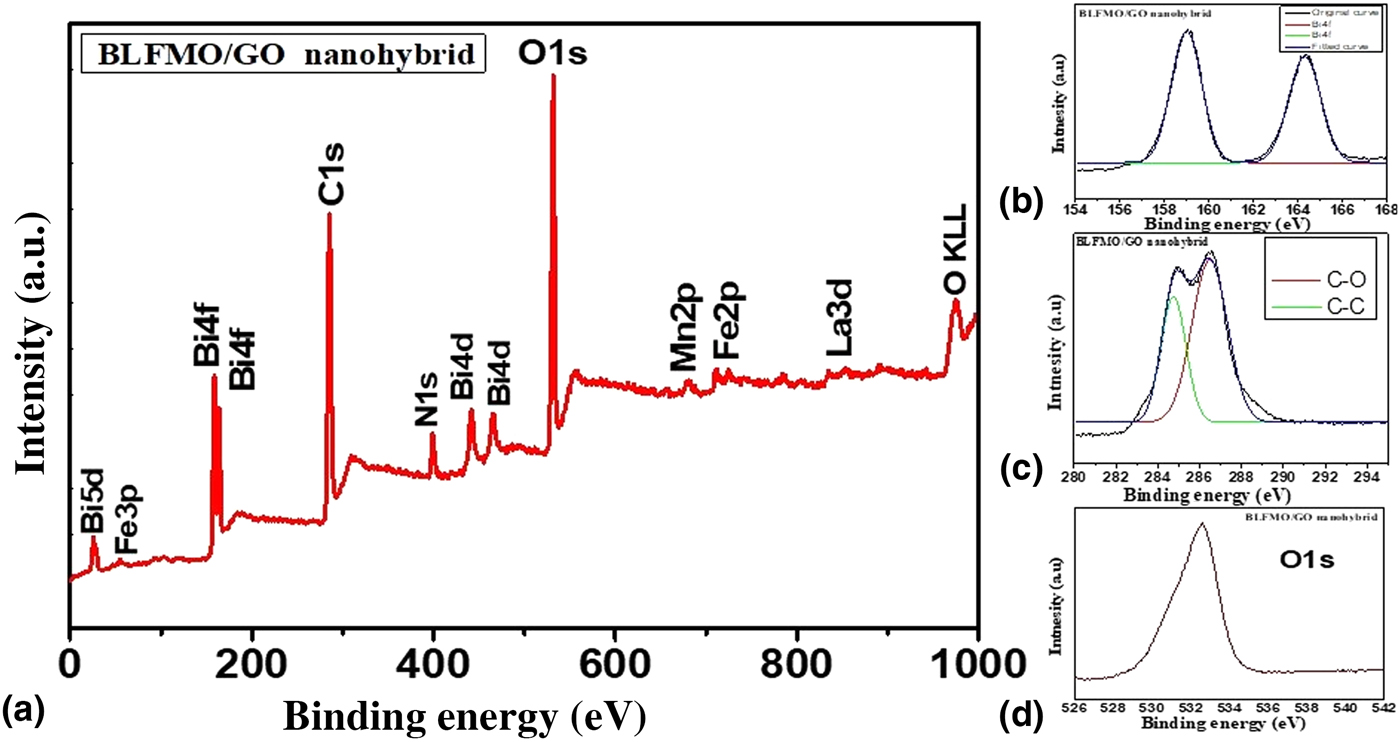
Figure 4. (a) XPS spectra of the BLFMO-15/GO nanohybrid. (b) XPS spectra for Bi4f. (c) XPS spectra for C1s containing C![]() C and C–O. (d) XPS spectra for O1s.
C and C–O. (d) XPS spectra for O1s.
The surface area measurements of nanohybrids were obtained by the analysis of nitrogen adsorption which represents the higher surface area of BLFO/GO and BLFMOs/GO nanohybrids than the pure forms of these ferrite nanoparticles. The highest surface area of 62.68 m2/g was observed for the BLFMO-15/GO nanohybrid. The type-IV BET isotherm and pore size distribution for BLFMO-15/GO are shown in Fig. 5. The sheet-like mesoporous system with an average pore diameter of 12.3 nm and a total pore volume of 0.193 cm3/g with less crystallinity was observed.
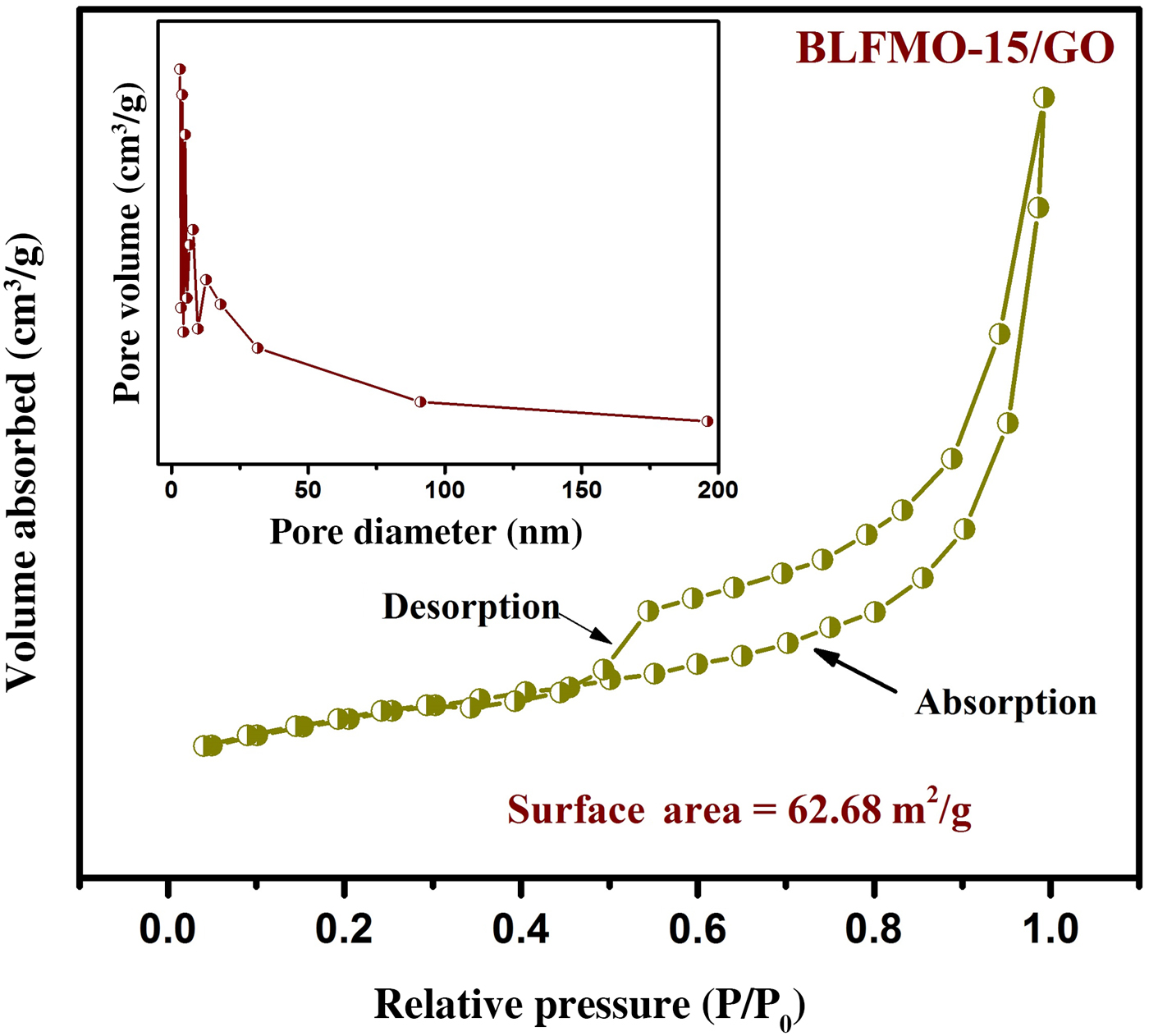
Figure 5. Nitrogen adsorption–desorption isotherm with BET specific surface area for the BLFMO-10/GO nanohybrid. Inset: BJH pore size distribution curve.
The addition of graphene within the nanohybrid causes the decrement inside crystallite size and hence, increment in the surface area.
The PL emission measurements were performed by using a fluorescence spectrophotometer for the BLFMO-5 and BLFMO-15 samples and the results are shown in Fig. 6. The PL spectra shown here give information regarding the photo-generated charge carrier transfer, electron–hole recombination, and migration in semiconductor photocatalysts.[Reference Shi, Liang, Ma, Wang and Sun53]
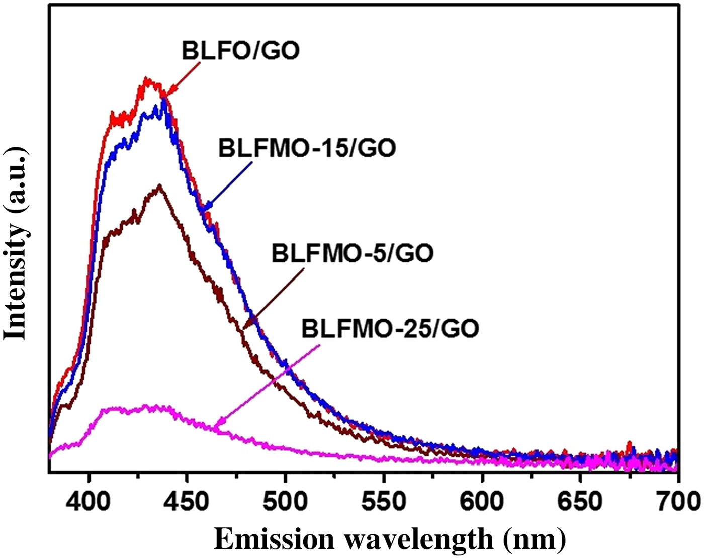
Figure 6. PL spectra of BLFMO-5/GO and BLFMO-15/GO nanohybrids.
In the PL spectra, the much lower the peak intensity the much higher the degradation efficiency of the nanohybrid. The PL intensity for BLFO/GO and BLFMO-15/GO is higher as compared with other nanohybrids and approximately equal as the photo-degradation of dye inside both of these is 4% and 5% in 30 min. The PL intensity is lower for the BLFMO-5/GO nanohybrid whose photo-degradation efficiency is 8% in 30 min. The PL is very low in the BLFMO-25/GO nanohybrid representing the lower electron–hole recombination rate and hence higher photocatalytic activity. The dye degradation efficiency inside BLFMO-25/GO is comparatively higher than other hybrid structures which is 15% in 30 min. Lower the PL intensity means more generation of active species (peroxides and OH- radicals) helps in enhancing the redox reactions over the hybrid surface with the organic dye molecules which results in quick and efficient dye extraction from the aqueous blend. After the introduction of graphene, the visible light generated charge carriers are effectively transported over the top of the photocatalyst under visible light irradiation as graphene behaves as a grabbing site for excited electrons and promotes an adequate charge separation over the photocatalyst surface and hence, improves the degradation efficiency of our nanohybrids.[Reference Liao, Chen, Quan, Yu and Zhao54]
Photocatalytic measurements
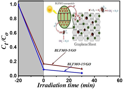
Figure 7 shows the general mechanism involved in the photodegradation of organic molecules using BLFMO/graphene nanohybrids. The electron–hole generation under visible light helps in deterioration of pollutants with the formation of water and carbon dioxide as by-products.
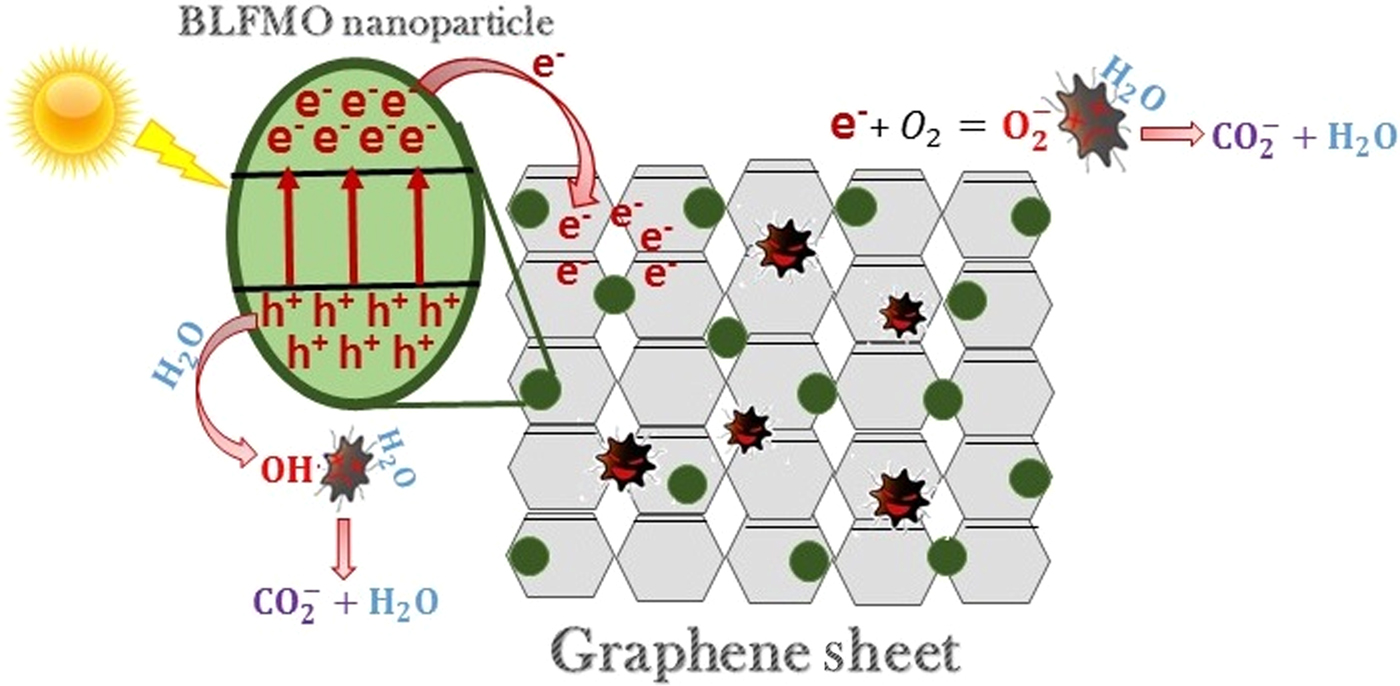
Figure 7. Photocatalytic mechanism of BLFMO–graphene nanocomposites.
It was found that the optical band-gap of nanohybrids of BiFeO3 with GO is significantly tuned to their pure form. The DRS for band-gap evaluation of BLFMO/GO series are presented in Fig. 8.
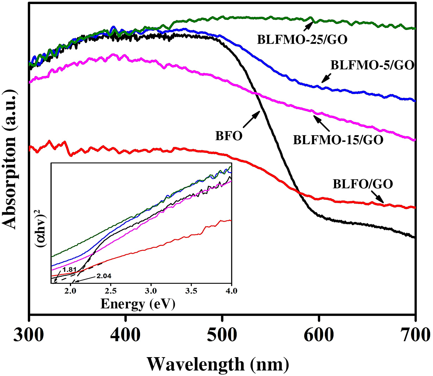
Figure 8. UV-vis absorption spectra for BiFeO3, BLFO, and BLFMO/GO; the inset is the measurement of the bands.
Two bulging characteristics of the reflectance spectra were noticed. First of all, the BLFMO/GO series exhibit approximately the similar optical absorption conduct as shown by pure BiFeO3 nanostructures around the 300–400 nm UV range, but also present a considerably higher visible light absorption in the range of 400–800 nm, near to peak limit of our reflectance measurements. Furthermore, the BLFMO/GO absorption is enough decreased within the range of 300–400 nm and is fairly superimposed with pure BiFeO3 and BLFO/GO at 400 nm and above. The sudden decline in absorption above 400 nm has been recorded by other researchers too[Reference Miriyala, Prashanthi and Thundat55] and was assigned to the BiFeO3 (pure sample) band edge. These features indicate that the nanohybrid of BLFMO with GO was favorable for visible to IR absorption. The near edge optical absorption is based upon Kubelka–Munk function, (αhυ) = A(hυ − E g)n/2 where h and E g are Planck's constant and band-gap energy while υ is the light frequency and A is a constant.[Reference Kubelka and Munk56]
The plots based on (αhυ)2 versus hυ shown in the inset of Fig. 8 provide the optical band-gaps of pure BiFeO3 with BLFMO/GO nanohybrids. By extrapolating the smooth part of these plots toward the x-axis we can determine the band-gap energies (E g) of the samples. Correspondingly, the band-gap energy for BiFeO3 was 2.04 eV which is well comparable with already recorded results.[Reference Gao, Chen, Yin, Dong, Ren, Yuan, Yu and Liu28, Reference Joshi, Jang, Borse and Lee31, Reference Guo, Fang, Dong, Zheng and Shen57] An increment in dopant concentration decreases the band-gap. Hence the measured reduced band-gap energies ware found within the range of 2.04–1.81 eV for BLFO/GO. The decrease in the band-gap energy empowers the improvement in photocatalytic behavior of BiFeO3,[Reference Satar, Aziz, Yaakob, Yahya, Hassan, Kudin and Kaus58] further reducing the bang-gap of BLFMO-5/GO and BLFMO-15/GO to 1.81 and 1.75 eV, respectively. For the small alterations in optical absorption for BLFMO-25/GO within the visible light range, it was quite difficult to calculate the outbreak of the decrement in optical absorption, as shown in Fig. 8 (inset) which is due to the limited impurity states. The photocatalysis of pure BFO and BLFMO/GO was verified by checking the elimination of organic dye pollutant CR in the presence of visible light.
Figure 9 shows photo-degradation effectiveness of BiFeO3 and BLFMO/GO nanohybrids under visible light. Excellent photocatalytic results were obtained for BLFMO-5/GO and BLFMO-15/GO among which CR was significantly degraded within the time interval of 30 min. The CR removal was approximately negligible for the BFO photocatalyst. The overall degradation relies over both catalytic (under dark conditions) and photocatalytic (presence of light radiations) activity of nanohybrids. The catalytic activity is highest in the BLFMO-15/GO nanohybrid (91%) which is attributed to more dye adsorption over the hybrid surface due to having a higher specific surface area while in BLFO/GO, BLFMO-GO, and BLFMO-25/GO it is 44%, 82%, and 70%. As compared with catalytic activity, the photocatalytic activity is higher in BLFMO-25/GO (15%) due to having a low carrier recombination rate (low PL intensity) while the photocatalytic activity in BLFO/GO, BLFMO-5/GO, and BLFMO-15/GO is 4%, 8%, and 5%. The total degradation rate among BLFO/GO, BLFMO-5/GO, BLFMO-15/GO, and BLFMO-25/GO is 77%, 90%, 96%, and 92%. The removal rate of dye was significantly improved by inserting GO inside BLFMO/GO nanohybrids which helps in increasing specific surface area and active transfer of charge carriers toward active sites due to being a trapping site for electrons. The XRD patterns of the BLFMO-5/GO and BLFMO-15/GO nanocomposites before and after photocatalytic reaction are shown in Fig. 10(a). The crystal structure of both, BLFMO-5/GO and BLFMO-15/GO photocatalysts did not change after photocatalytic reaction. There was no presence of any other secondary phase at the end of reaction. Furthermore, the stability of these photocatalysts was also inspected up to four cycles and is illustrated in Fig. 10(b); the photocatalytic efficiency of nanohybrids was not affected with the repetition of the reaction. The constancy in the catalytic activity confirms that BLFMO/GO nanohybrids are well persistent photocatalysts and show very good potential for different applications.
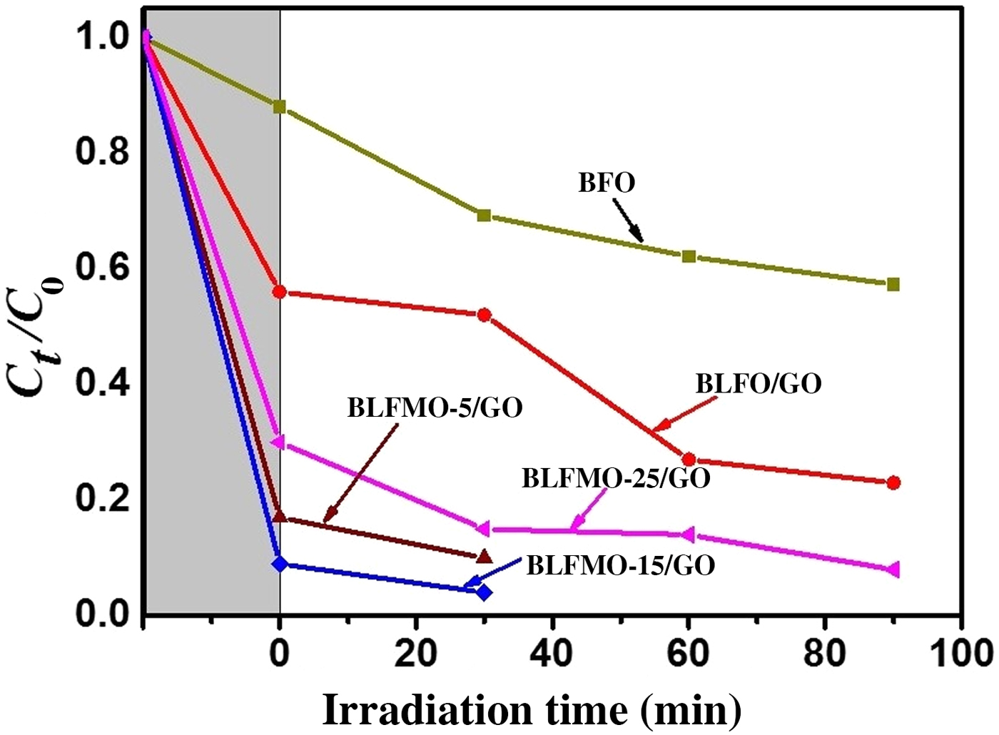
Figure 9. The photocatalytic activities of BLFMO/GO nanohybrids in comparison with pure BiFeO3.
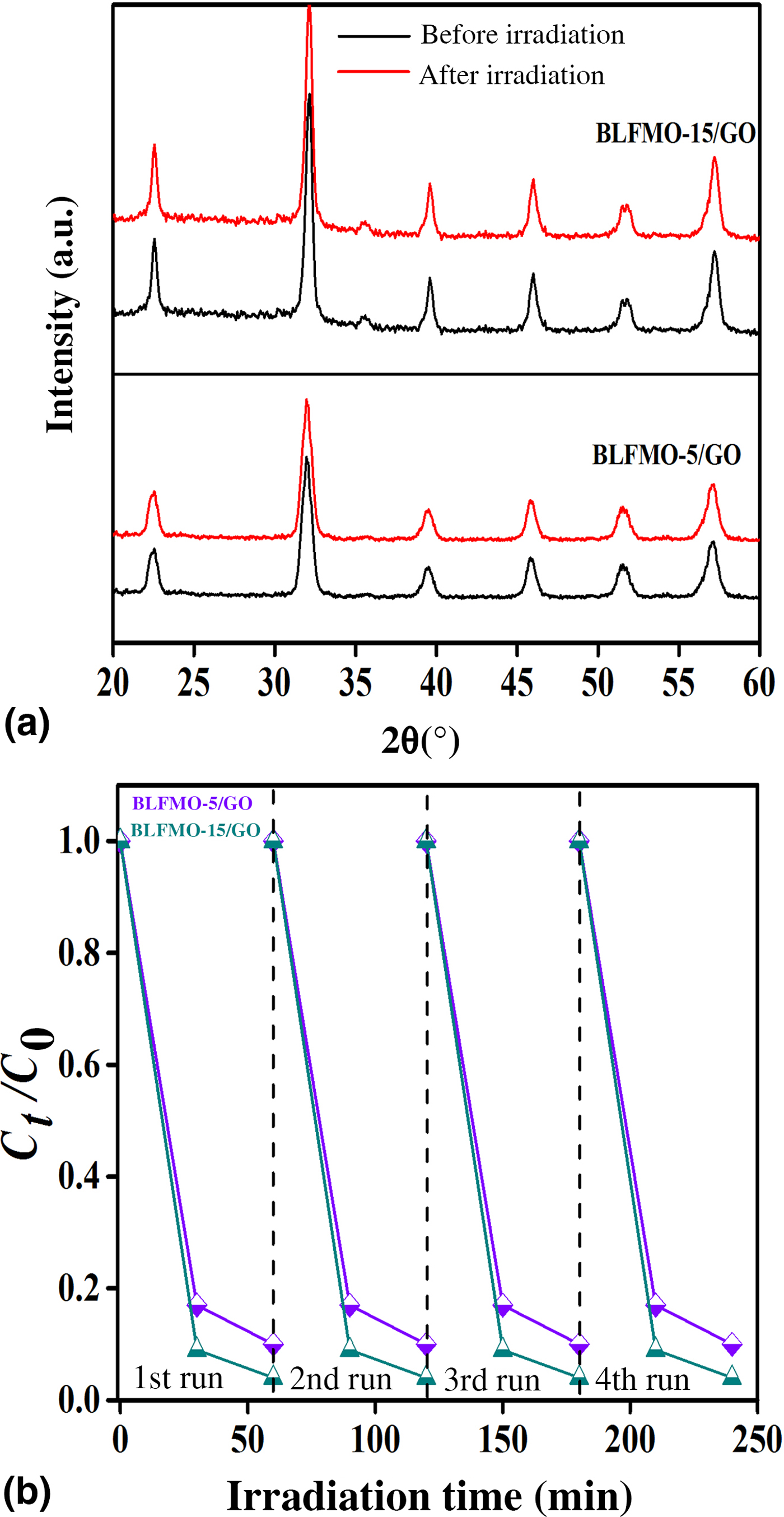
Figure 10. (a) XRD curves of BLFMO/GO nanohybrids in the beginning and at the end of photocatalytic reaction. (b) Stable photocatalytic curves for the BLFMO-5/GO and BLFMO-15/GO nanohybrids up to four cycles.
Conclusion
BFO co-doped nanoparticles (BLFO and BLFMO) were prepared via the sol–gel fabrication technique and the GO was chemically synthesized. The BLFO/GO and BLFMO/GO nanohybrids were prepared by a co-ppt method. Well embedded mesoporous nanoparticle-two-dimensional sheet-like nanostructures were obtained and analyzed for photocatalytic application. BLFMO-5/GO and BLFMO-15/GO were obtained with sizeable surface areas of 30.06 and 62.68 m2/g, respectively. The enhanced catalytic activity was observed in nanohybrids (96% in 30 min) because of the incorporation of GO layers within the nanoparticles. Graphene, due to the presence of more reactive sites, results in more electron–hole pair generation with a low recombination rate, hence, an increase in the photocatalytic degradation. Higher surface area encourages the nanohybrids to absorb a broad spectrum of visible light thus, encourages the fast degradation of organic dye. The cost effective preparation and higher photocatalytic efficiency of these BLFMO/GO nanohybrids make them suitable candidates for useful commercial applications.
Acknowledgment
The Higher Education Commission (HEC) of Pakistan funded the research activity under the Project #39/HEC/R&D/PAKUS/2017/783 and 6040/Federal/NRPU/R&D/HEC/2016 to carry out part of the research work within Pakistan. This work was also funded by benevolent support of United States Agency for International Development (USAID) under the Pakistan–U.S. Science & Technology Cooperation Program grant. The essence does not inevitably express the perspectives of the US Government.


