1. INTRODUCTION
Autonomous navigation technology enables a spacecraft to determine its position and velocity by itself, without need for ground tracking. This technology can not only improve the reliability of a space mission, but also reduce operational complexity while working.
The capability of spacecraft autonomous navigation relies mainly on its navigation method and navigation algorithm. A variety of autonomous navigation methods have been proposed so far: photoelectric autonomous navigation (fully autonomous navigation), including horizon-sensing (Ning and Fang, Reference Ning and Fang2007), magnetometer-based navigation (Shorshi and Bar-Itzhack, Reference Shorshi and Bar-Itzhack1995), star sensor (Ning and Fang, Reference Ning and Fang2008) and inertial navigation (Xu and Fang, Reference Xu and Fang2008); inter-satellite link (semi-autonomous navigation), including Doppler measurement (Ning and Fang, Reference Ning and Fang2008) and Global Positioning System (Choi et al., Reference Choi, Yoon, Lee, Park and Choi2010; Chiaradia et al., Reference Chiaradia, Kuga and Prado2003; Yoon et al., Reference Yoon, Lee and Choi2000; Bolandi et al., Reference Bolandi, Ashtari Larki, Abedi and Esmailzade2013) and so on. Unlike other autonomous navigation methods, GPS has the following advantages: (1) global coverage; (2) low cost; (3) able to determine positions with centimetre level accuracy and measure velocities with high precision by Differential GPS (DGPS) (Chiaradia et al., Reference Chiaradia, Kuga and Prado2003). Therefore, GPS is widely applied to spacecraft autonomous navigation.
A nonlinear filtering algorithm is employed for autonomous navigation. The filtering algorithms applied to spacecraft autonomous navigation can be divided into three classes according to the handling methods of nonlinear problems. The first is the approximation analytic method, which approximates the nonlinear measurement and transition equations with the Taylor series expansion, e.g. Extended Kalman Filter (EKF). The second is the deterministic sampling method, which approximates the underlying density functions of state-vectors by producing a variety of sigma points according to a rule, e.g. Unscented Kalman Filter (UKF). The last is a method based on the Monte Carlo simulation, which approximates the posterior density functions on the basis of the law of large numbers, e.g. Particle Filter (PF). EKF is widely used in spacecraft autonomous navigation (Shorshi and Bar-Itzhack, Reference Shorshi and Bar-Itzhack1995; Yim et al., Reference Yim, Crassidis and Junkins2000; Zhang et al., Reference Zhang, Cheng, Yang, Pan and Gu2009). Compared with other nonlinear filtering algorithms, EKF has an algorithm design of low complexity and its estimation accuracy satisfies the requirements of practical applications. However, EKF needs to linearize the measurement and transition equations in real time, which leads to a large online calculation quantity. It will also introduce large approximation model errors that may lead to poor filtering performance or sometimes divergence of the filter in a highly nonlinear and non-Gaussian system.
In order to improve the estimation accuracy and considering the lower approximation model errors than EKF, the application of UKF in spacecraft autonomous navigation has also received great attention (Ali and Fang, Reference Ali and Fang2006; Cheng et al., Reference Cheng, Chen, Landry, Zhao and Guan2014; Liu et al., Reference Liu, Kang, White, Ma and Tian2011). UKF uses the actual nonlinear model and a set of sigma sample points produced by the unscented transformation to capture the mean and covariance of states (Julier and Uhlmann, Reference Julier and Uhlmann2004). This has proved to have a better performance than EKF in nonlinear system state estimation. Nevertheless, UKF has not only a complicated algorithm design and large online calculation quantity, but also serious influence on the preference in system state estimation, caused by the uncertainty of the true distribution (Song and Han, Reference Song and Han2008). The poor stability of UKF limits its application in spacecraft autonomous navigation to some extent. Compared with UKF, PF has not only a high-precision state estimation, but also stable performance with an uncertain distribution. PF approximates the posterior density function of state vector by obtaining a random sample. It achieves the optimal estimation by adjusting the weights of samples and changing samples based on measured data (Song et al., Reference Song, Han and Geng2009). However, the large online calculation quantity caused by vast samples and the complicated algorithm design also limit the application of PF in spacecraft autonomous navigation, in spite of the above advantages. A lot of modified nonlinear filtering algorithms based on EKF, UKF and PF have appeared in recent years (Ning and Fang, Reference Ning and Fang2008; Li et al., Reference Li, Wang and Tan2012; Yang et al., Reference Yang, Li and Li2014). In order to improve the performance of UKF in case of uncertain noise statistic characteristics, a noise statistic estimator was designed to estimate uncertain noise characteristics online for UKF by Cheng et al. (Reference Cheng, Chen, Landry, Zhao and Guan2014). Moreover, the single algorithms can be integrated to enhance their estimation performance. Ning and Fang (Reference Ning and Fang2008) proposed the unscented particle filter by combining UKF with PF to enhance the stability of UKF, while according to the research of Yang et al. (Reference Yang, Li and Li2014), by designing a switch-mode information fusion filter, the iterated square root unscented filter was combined with EKF to strengthen the reliability of autonomous navigation. However, it will be more and more difficult for the increasingly complex algorithm to provide real-time navigation, especially for modern spacecraft with limited computing resources.
Aiming at improving the poor real-time performance of the nonlinear filtering algorithms applied to spacecraft autonomous navigation, an effective spacecraft autonomous navigation algorithm based on Polytopic Linear Differential Inclusion (PLDI) is proposed in this paper. Firstly it is demonstrated that the estimation error system of spacecraft autonomous navigation can be modelled as a Polytopic Linear Differential Inclusion Systems (PLDIs) model and the problem of the nonlinear filtering is converted to the problem of multiple linear time-invariant systems in the form of convex combination on linear filtering. Then the PLDIs model of spacecraft autonomous navigation is determined by TP model transformation. And on this basis the spacecraft autonomous navigation algorithm based on PLDI is proposed by combining multi-model Kalman filtering with data fusion. This algorithm has better performance in state estimation and lower complexity of algorithm design than EKF.
This paper is structured as follows: after this introduction, the orbit dynamic model and GPS measurement model are introduced in Section 2. In Section 3, it is demonstrated that the estimation error system of spacecraft autonomous navigation can be modelled as a PLDIs model. Meanwhile, the methods for determining the PLDIs model and the spacecraft autonomous navigation algorithm based on PLDI are given. The navigation algorithm is verified by using simulation in Section 4 and the simulation results of the algorithm will be compared with that of EKF. Conclusions are drawn in Section 5.
2. SPACECRAFT AUTONOMOUS GPS NAVIGATION MODEL
2.1. Orbit dynamic model
WGS84 is selected as the reference coordinate system, and we suppose that the high order terms of disturbance caused by the Earth, Sun, Moon or atmosphere are ignored. The equations of this model are given below (Ning and Fang, Reference Ning and Fang2007):
 $$\left\{ \eqalign{\displaystyle{{{\rm d}x} \over {{\rm d}t}} = & v_x + w_x \cr \displaystyle{{{\rm d}y} \over {{\rm d}t}} = & v_y + w_y \cr \displaystyle{{{\rm d}z} \over {{\rm d}t}} = & v_z + w_z \cr \displaystyle{{{\rm d}v_x} \over {{\rm d}t}} = & - \mu \displaystyle{x \over {r^3}} \left[ {1 - J_2 \left( {\displaystyle{{R_e} \over r}} \right)\left( {7.5\displaystyle{{z^2} \over {r^2}} - 1.5} \right)} \right] + a_x + w_{v_x} \cr \displaystyle{{{\rm d}v_y} \over {{\rm d}t}} = & - \mu \displaystyle{y \over {r^3}} \left[ {1 - J_2 \left( {\displaystyle{{R_e} \over r}} \right)\left( {7.5\displaystyle{{z^2} \over {r^2}} - 1.5} \right)} \right] + a_y + w_{v_y} \cr \displaystyle{{{\rm d}v_z} \over {{\rm d}t}} = & - \mu \displaystyle{z \over {r^3}} \left[ {1 - J_2 \left( {\displaystyle{{R_e} \over r}} \right)\left( {7.5\displaystyle{{z^2} \over {r^2}} - 4.5} \right)} \right] + a_z + w_{v_z} \cr \displaystyle{{{\rm d}a_x} \over {{\rm d}t}} = & - \alpha _x a_x + w_{a_x} \cr \displaystyle{{{\rm d}a_y} \over {{\rm d}t}} = & - \alpha _y a_y + w_{a_y} \cr \displaystyle{{{\rm d}a_z} \over {{\rm d}t}} = & - \alpha _z a_z + w_{a_z}} \right.$$
where r represents  $\sqrt {\left( {x^2 + y^2 + z^2} \right)} $, x, v x, y, vy, z, vz are satellite positions and velocities on the three axes respectively; a x, ay, az are part of the perturbing accelerations on the three axes respectively which can be approximated by the Singer model; α x, αy, αz are reciprocals of the correlation time constants on the three axes respectively; R e is the earth radius; μ is the gravitational constant of the earth; J 2 is the second zonal coefficient.
2.2. Measurement model of GPS
The theory of satellite navigation is illustrated by Figure 1.

Figure 1. Diagram of satellite navigation.
The pseudo-range between spacecraft receiver and navigation satellite is regarded as the observation of the measurement equations. To determine unknown position vectors of the target spacecraft in space, the position information of three navigation satellites needs to be obtained. Considering that the clock bias can produce a big observation error that can neither be ignored nor be predicted, the clock bias is regarded as an unknown quantity that needs to be determined. As a result, the information of a fourth navigation satellite is needed. Now, the position information of four navigation satellites need to be obtained to determine the position vectors of the target spacecraft and clock bias of receiver using the least squares method. The number of observable satellites is assumed to be four, and the measurement equations are given as follows:
 $$\left\{ {\matrix{ {\rho _1 = \sqrt {\left( {x^1 - x} \right)^2 + \left( {y^1 - y} \right)^2 + \left( {z^1 - z} \right)^2} + c\delta t_u + \varepsilon _1} \cr {\rho _2 = \sqrt {\left( {x^2 - x} \right)^2 + \left( {y^2 - y} \right)^2 + \left( {z^2 - z} \right)^2} + c\delta t_u + \varepsilon _2} \cr {\rho _3 = \sqrt {\left( {x^3 - x} \right)^2 + \left( {y^3 - y} \right)^2 + \left( {z^3 - z} \right)^2} + c\delta t_u + \varepsilon _3} \cr {\rho _4 = \sqrt {\left( {x^4 - x} \right)^2 + \left( {y^4 - y} \right)^2 + \left( {z^4 - z} \right)^2} + c\delta t_u + \varepsilon _4} \cr}} \right.$$
where [xi, yi, zi]T (i = 1, 2, 3, 4), [x, y, z]T denote the position of observable satellites and position of spacecraft receiver in the WGS84 coordinate system respectively; c denotes the velocity of light; δt u denotes the GPS clock bias; ρ i (i = 1, 2, 3, 4) denotes the pseudo-range between spacecraft receiver and observable satellites; ε i is the measurement noise and assumed to be zero-mean white noise.
Define δf u as the clock bias drift of receiver, and δt u is caused by the clock bias drift with the following equation:
 $$\dot \delta t_u = \delta f_u $$
In practice, δf u is usually regarded as coloured noise, and can be modelled as a Markov model:
 $$\dot \delta f_u = - \lambda _\xi \delta f_u + s$$
where λ ξ denotes the reciprocal of the correlation time constants for the model, s denotes the zero-mean Gaussian noise.
2.3. Autonomous navigation system model based on GPS measurement
X = [x, v x, ax, y, vy, ay, z, vz, az, δtu, δfu]T is regarded as the state variable of an autonomous navigation system, where δt u and δf u denote the clock bias and clock bias drift of GPS receiver respectively. According to Equations (1) to (4), the autonomous navigation model based on GPS measurement can be given by:
 $$\eqalign{{\bi \hat X} &= f\,({\bi X}) + {\bi w} \cr {\bi Z} &= h({\bi X}) + {\bi \varepsilon}} $$
where  ${\bi X} \in {\opf R}^n $ and ${\bi Z} \in {\opf R}^m $ denote the state variable and observation which is comprised of the pseudo-range between target spacecraft and GPS navigation satellites; f(·) and h(·) denote the general equation of Equation (1) and Equation (2) respectively; w = (w x, wvx, wax, wy, wvy, way, wz, wvz, waz, 0, w t)T, ε = (ε 1, ε 2, ε 3, ε 4)T denotes the system noise and measurement noise respectively.
3. SPACECRAFT AUTONOMOUS NAVIGATION ALGORITHM BASED ON PLDI
EKF needs to linearize the nonlinear system model in real time and update the Jacobian matrices online. However, updating the Jacobian matrices may lead to not only poor real-time performance, but also higher complexity of the algorithm design in case the dynamic and measurement models have high nonlinearities. In order to simplify the algorithm design, a spacecraft autonomous navigation algorithm based on PLDI (PLDI Kalman Filter (PKF)) is proposed in this Section.
3.1. PLDIs model of autonomous navigation estimation error system ${\bi \hat X}$ is assumed to be the optimal system state estimation. The system state and observed estimation satisfy:
 $$\eqalign{{\bi \dot {\hat X}} = f\left( {{\bi \hat X}} \right) \cr {\bi \hat Z} = h\left( {{\bi \hat X}} \right)} $$
where  ${\bi \hat Z}$ denotes the observed estimation of measurement model.
The state estimation error and observed residual can be defined as:
 $$\eqalign{\Delta {\bi X} = & {\bi X} - {\bi \hat X} \cr \Delta {\bi Z} = & {\bi Z} - {\bi \hat Z}} $$
Therefore, the estimation error model of autonomous navigation system can be given by:
 $$\eqalign{\Delta {\bi \dot X} = f\left( {\bi X} \right) - f\left( {{\bi \hat X}} \right) + {\bi w} \cr \Delta {\bi Z} = h\left( {\bi X} \right) - h\left( {{\bi \hat X}} \right) + {\bi \varepsilon}} $$
Theorem 1
Ωx is a subset of n-dimensional space,  ${\bi \Omega} _x \subseteq {\opf R}^n $, and the vector function f is defined as: ${\bi \Omega} _x \to {\opf R}^m $. If Ωx and f satisfy the following conditions:
(1) f is continuously differentiable;
(2) The arbitrary point X and vector H at the subset Ωx satisfy: X + α H ∈ Ωx;
(3) Partial derivatives of f vary in a bounded domain belonging to ${\opf R}^{m \times n} $;

Then,
 $$f\left( {{\bi X} + {\bi H}} \right) - f\left( {\bi X} \right) \in Co\left( {{\bi \Omega} _f} \right){\bi H}$$
where 0 ⩽ α ⩽ 1,  ${\bi H} \in {\opf R}^n $, Co(Ωf) is the convex hull generated by Ωf.
Proof:
The vector function  $f{\hskip -2pt}:{\bi \Omega} _x \to {\opf R}^m $ is continuously differentiable. The arbitrary point X and X + H ∈ Ωx satisfy X + α H ∈ Ωx, thus according to differential mean value theorem of vector function (de Boor, Reference De Boor2005) we have:
 $$f\,({\bi X} + {\bi H}) - f\,({\bi X}) = [\int_0^1 {\nabla f\,({\bi X} + \alpha {\bi H}){\rm d}\alpha} ]{\bi H}$$
where ∇f is the partial derivative of f, namely, the Jacobian matrix of f. Therefore,
 $$f_i ({\bi X} + {\bi H}) - f_i ({\bi X}) = \int_0^1 {\sum\limits_{\,j = 1}^n {\left[\displaystyle{{\partial f_i} \over {\partial x_j}} ({\bi X} + \alpha {\bi H})h_j\right ]} {\rm d}\alpha} $$
where i = 1, 2···m. Because partial derivatives of f vary in a bounded domain belonging to  ${\opf R}^{m \times n} $, the value of each element in ∇f is bounded, and can be expressed as:
 $$\eqalign{\nabla f_{{\rm ij}} = & \displaystyle{{\partial f_i} \over {\partial x_j}} \cr \nabla f_{{\rm ij}}^{\max} = & \max \left( {\nabla f_{{\rm ij}} \left( {{\bi X} + \alpha {\bi H}} \right)} \right) \cr \nabla f_{{\rm ij}}^{\min} = & \min \left( {\nabla f_{{\rm ij}} \left( {{\bi X} + \alpha {\bi H}} \right)} \right)} $$
∇f ij can also be expressed as:
 $$\nabla f_{{\rm ij}} ({\bi X} + \alpha {\bi H}) = \lambda _1 \nabla f_{{\rm ij}}^{\max} + \lambda _2 \nabla f_{{\rm ij}}^{\min} $$
where,
 $$\eqalign{\lambda _1 = & \displaystyle{{\nabla f_{{\rm ij}} ({\bi X} + \alpha {\bi H}) - \nabla f_{{\rm ij}}^{\min}} \over {\nabla f_{{\rm ij}}^{\max} - \nabla f_{{\rm ij}}^{\min}}} \cr \lambda _2 = & \displaystyle{{\nabla f_{{\rm ij}}^{\max} - \nabla f_{{\rm ij}} ({\bi X} + \alpha {\bi H})} \over {\nabla f_{{\rm ij}}^{\max} - \nabla f_{{\rm ij}}^{\min}}}} $$
When ∇f ijmax = ∇f ijmin, one of λ 1 and λ 2 can be assumed to be 1 and the other is assumed to be 0. As a result, the above equation holds. According to the above equation, ranges of λ 1 and λ 2 are 0 ⩽ λ 1 ⩽ 1, 0 ⩽ λ 2 ⩽ 1. Therefore, according to Equation (12):
 $$\nabla f_{{\rm ij}} ({\bi X} + \alpha {\bi H}) \in Co(\nabla f_{{\rm ij}}^{\max}, \nabla f_{{\rm ij}}^{\min} )$$
The following equation can be given by substituting the above equation into Equation (10):
 $$f_i \left( {{\bi X} + {\bi H}} \right) - f_i \left( {\bi X} \right) \in \int_0^1 {\sum\limits_{\,j = 1}^n {\left[ {Co(\nabla f_{{\rm ij}}^{\max}, \nabla f_{{\rm ij}}^{\min} )h_j} \right]} {\rm d}\alpha} $$
Let Ωi be Ωi = {a|a j ∈{∇f ijmax, ∇f ijmin}, j = 1, 2···n}, namely, each point at set Ωi is  ${\bi a} \in {\opf R}^n $, a j is the n-th element of a and its value is ∇f ijmax or ∇f ijmin. Thus, the above equation can also be expressed as:
 $$f_i \left( {{\bi X} + {\bi H}} \right) - f_i \left( {\bi X} \right) \in \int_0^1 {Co\left( {{\bi \Omega} _{\bi i}} \right){\bi H}} {\rm d}\alpha $$
Considering that the integral term is irrelevant to α, the above equation is equivalent to:
 $$f_i \left( {{\bi X} + {\bi H}} \right) - f_i \left( {\bi X} \right) \in Co\left( {{\bi \Omega} _i} \right){\bi H}$$
The above equation shows that each row in the Jacobian matrix of f can be expressed in the form of differential inclusion,  $\displaystyle{{{\rm \partial} f_i} \over {\partial {\bi X}}} = Co({\bi \Omega} _i )$. The left side of Equation (9) can also be expressed as:
 $$\eqalign{\,f\left( {{\bi X} + {\bi H}} \right) - f\left( {\bi X} \right) &= \sum\limits_i^m {\left( {\,f_i \left( {{\bi X} + {\bi H}} \right) - f_i \left( {\bi X} \right)} \right)} {\bi I}_{m \times 1}^i \cr & \in \sum\limits_i^m {\left[ {Co({\bi \Omega} _i ){\bi H}} \right]} {\bi I}_{m \times 1}^i} $$
Where  ${\bi I}_{m \times 1}^i $ denotes the i-th unit of space ${\opf R}^{m \times 1} $ whose elements are all 1. According to Equation (17), the above equation is equivalent to:
 $$f\left( {{\bi X} + {\bi H}} \right) - f\left( {\bi X} \right) \in Co\left( {{\bi \Omega} _f} \right){\bi H}$$
where Ωf = {a|a ij ∈ {∇f ijmax, ∇f ijmin}, i= 1, 2···m; j = 1, 2···n} means that each point in Ωf is  ${\bi a} \in {\opf R}^{m \times n} $, and the value of element in a, a ij, is ∇f ijmax or ∇f ijmin.
QED.
According to Theorem 1, the estimation error system represented by Equation (7) can be expressed as:
 $$\eqalign{& \Delta {\bi \dot X} \in Co({\bi \Omega} _f )\Delta {\bi X} + {\bi w} \cr & \Delta {\bi Z} \in Co({\bi \Omega} _h )\Delta {\bi X} + {\bi \varepsilon}} $$
Theorem 2
Considering the nonlinear system represented by Equation (5), if f(·), h(·) are both continuously differentiable and the value set of the Jacobian matrices is a bounded set, the estimation error system can be modelled as follows:
 $$\eqalign{\Delta {\bi \dot X} = {\bi A}\Delta {\bi X} + {\bi w} \cr \Delta {\bi Z} = {\bi C}\Delta {\bi X} + {\bi \varepsilon}} $$
where matrix A and matrix C are defined as:
 $$({\bi A},{\bi C}) = \sum\limits_{i = 1}^l {\lambda _i ({\bi A}_i, {\bi C}_i )} $$
where λ i are weights of convex combination, and  $\sum\limits_{i = 1}^l {\lambda _i} = 1$, 0 ⩽ λ i ⩽ 1, Ai and Ci are system vertex matrices of the PLDIs model; l is number of the system vertex matrices.
Proof:
The estimation error system represented by Equation (7) can be expressed as:
 $$\left( {\matrix{ {\Delta {\bi \dot X}} \cr {\Delta {\bi Z}} \cr}} \right) = \left( {\matrix{ {\,f\left( {{\bi \hat X} + \Delta {\bi X}} \right)} \cr {h\left( {{\bi \hat X} + \Delta {\bi X}} \right)} \cr}} \right) - \left( {\matrix{ {\,f\left( {{\bi \hat X}} \right)} \cr {h\left( {{\bi \hat X}} \right)} \cr}} \right) + \left( {\matrix{ {\bi w} \cr {\bi \varepsilon} \cr}} \right)$$
For a nonlinear filtering algorithm with good estimation performance, the difference between state estimation and real state of system, ΔX, tends to be zero or very small. As a result, we can find a proper subset  ${\bi \Omega} _x \subset {\opf R}^n $ which includes ${\bi \hat X}$ and ${\bi \hat X}$ + αΔX, where 0 ⩽ α ⩽ 1. Considering that nonlinear functions f(·), h(·) are both continuously differentiable and partial derivatives of them vary in a bounded domain, the above estimation error system can be expressed as:
 $$\left( {\matrix{ {\Delta {\bi \hat X}} \cr {\Delta {\bi Z}} \cr}} \right) \in Co\left( {{\bi \Omega} _{{\rm fh}}} \right)\Delta {\bi X} + \left( {\matrix{ {\bi w} \cr {\bi \varepsilon} \cr}} \right)$$
Where 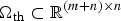 ${\bi \Omega} _{{\rm th}} \subset {\opf R}^{(m + n) \times n} $ is the value set of partial derivative of nonlinear function g (X) = (f(X)T h (X)T)T with respect to the system state variable. The above equation represents a Linear Differential Inclusion system (LDIs). In general, Co(Ωfh) can be approximated by an endo-tangent polytope with any accuracy (Xie et al., Reference Xie, Soh and Du2005; Li, Reference Li2002). Therefore, there will always be a polytope Ω satisfying:
 $$Co\left( {{\bi \Omega} _{{\rm fh}}} \right) \approx {\bi \Omega} = \left\{ {\left. {\left( {\matrix{ {\bi A} \cr {\bi C} \cr}} \right)} \right|\left( {\matrix{ {\bi A} \cr {\bi C} \cr}} \right) = \sum\limits_{i = 1}^l {\lambda _i \left( {\matrix{ {{\bi A}_i} \cr {{\bi C}_i} \cr}} \right)}, 0 \les \lambda _i \les 1} \right\}$$
Thus, Equation (23) can be expressed in the form of Equation (21).
QED.
According to Theorem 1, Theorem 2 and the autonomous navigation estimation error system indicated by Equation (7), an estimation error system can be modelled as the PLDIs model. According to the TP model transformation (Baranyi, Reference Baranyi2004), the PLDIs model can be determined by the following steps:
Step 1: Determine the bound domain Ωp. Considering that parameters included by the Jacobian matrices are positions on three axes, x, y, z, Ωp can be expressed as Ωp = [c 1, d 1] × [c 2, d 2] × [c 3, d 3].
Step 2: Divide Ωp into I n grids uniformly distributed on each dimensionality:  ${\bi p}_n \in \{ {\bi p}_{n,1} ,{\bi p}_{n,2} ,\cdots {\bi p}_{n,I_n } \} $ where $c_n \les p_{n,1} \les p_{n,2} \cdots \les p_{n,I_n } \les d_n ,n = 1,2,3;$
Step 3: Sample the functions S(pn,in) over the hyper rectangular grid and store the sample matrices in the tensor S;
Step 4: Execute the Higher Order Singular Value Decomposition (HOSVD) on each dimensionality of tensor S, and discard not only zero n-mode singular values but also part of the non-zero n-mode singular values. Normalised n-mode matrices Un, and tensor S are approximated by: 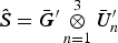 ${\bi \hat S} = {\bi \bar G}^{\prime} \mathop \otimes \limits_{n = 1}^3 {\bi \bar U}_n^{\prime}$
Step 5: Extract the vertex matrices Cj for the PLDIs model from  ${\bi \bar G}'$.
The vertex systems of autonomous navigation system which is modelled as a PLDIs model are determined by TP model transformation. It means that the Jacobian matrix is expressed in the form of convex combination, which is composed by a variety of constant matrices. S(p) is defined as a matrix composed by Jacobian matrices:
 $${\bi S}({\bi p}) = \left( {\displaystyle{{\partial h} \over {\partial {\bi X}}}} \right),{\bi p}{\rm =} {\bi X}$$
According to TP model transformation, S(p) can be approximately expressed in the form of convex combination, composed by a variety of constant matrices.
 $${\bi S}\left( {\bi p} \right) \approx \sum\limits_{i = 1}^l {\lambda _i \left( {\bi p} \right){\bi S}_i} = \sum\limits_{i = 1}^l {\lambda _i \left( {\bi p} \right){\bi C}_i} $$
where λ i (p) are weights of convex combination, and 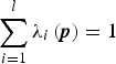 $\sum\limits_{i = 1}^l {\lambda _i \left( {\bi p} \right)} = 1$, 0 ⩽ λ i(p) ⩽ 1, Ci is the constant matrices.
Therefore, the autonomous navigation estimation error system can be described by a PLDIs model as follows:
 $$\eqalign{& {\rm \Delta} {\bi \dot X = \Phi} {\rm \Delta} {\bi X + B\upsilon} \cr & {\rm \Delta} {\bi Z = C}{\rm \Delta} {\bi X + D\upsilon}} $$
where
 $$\eqalign{& {\bi B}\,=\,\left[ {{\bi I}_{11 \times 11}\,0_{11 \times 4}} \right],{\bi D} = \left[ {0_{4 \times 11}\,{\bi I}_{4 \times 4}} \right],\,{\bi \upsilon} = \left[ \matrix{{\bi w} \cr{\bi \varepsilon} } \right] \cr & {\bi C} \in \left\{ {\left. {\bi C} \right|{\bi C} = \sum\limits_{\,j = 1}^l {\lambda _j {\bi C}_j, 0} \les \lambda _j \les 1,\sum\limits_{\,j = 1}^l {\lambda _j} = 1} \right\}} $$
where Cj denotes the j-th vertex system matrices, and Cj is constant matrix; l is number of the vertex system matrices.
3.2. Spacecraft autonomous navigation algorithm
The PLDIs model of spacecraft autonomous navigation system is determined by TP model transformation as above, and the PKF algorithm will be given by following steps based on the above results.
Forecast states:
 $${\bi \hat X}_{k/k - 1} = {\bi \Phi} _{k/k - 1} {\bi \hat X}_{k - 1} $$
Forecast estimation error covariance matrix:
 $${\bi \hat P}_{k/k - 1} = {\bi \Phi} _{k/k - 1} {\bi \hat P}_{k - 1} \left( {{\bi \Phi} _{k/k - 1}} \right)^T + {\bi Q}_k $$
Calculate the observed residual:
 $$\Delta {\bi Z}_k = {\bi Z}_k - {\bi \hat Z}_k = {\bi Z}_k - h\left( {{\bi \hat X}_{k/k - 1}} \right)$$
Calculate gain: Calculate different filtering gains according to different Cj.
 $${\bi K}_{\,j,k} = {\bi \hat P}_{k/k - 1} {\bi C}_j ^T \left( {{\bi C}_j {\bi \hat P}_{k/k - 1} {\bi C}_j ^T + {\bi R}_k} \right)^{ - 1} $$
Update estimation error covariance matrix: Different estimation error covariance matrices are obtained by different gains Kj,k and Cj, and the global estimation error covariance matrix is obtained according to data fusion.
 $${\bi \hat P}_{\,j,k} = \left( {{\bi I}_n - {\bi K}_{\,j,k} {\bi C}_j} \right){\bi \hat P}_{k/k - 1} \left( {{\bi I}_n - {\bi K}_{\,j,k} {\bi C}_j} \right)^T + \, {\bi K}_{\,j,k} {\bi R}_k {\bi K}_{\,j,k} ^T $$
 $${\bi \hat P}_k^{ - 1} = {{\sum\limits_{j = 1}^l {s_j \left( {{\bi \hat P}_{j,k}} \right)^{ - 1}}} \Big/ {\sum\limits_{j = 1}^l {s_j}}} $$
Calculate correcting value of state estimation: Different correcting values are obtained for different gains Kj,k, and the global correcting value can be given according to data fusion.
 $$\Delta {\bi \hat X}_{\,j,k} = {\bi K}_{\,j,k} \Delta {\bi Z}_k $$
 $$\Delta {\bi \hat X}_k = {{\sum\limits_{j = 1}^l {\left( {s_j \Delta {\bi \hat X}_{j,k}} \right)}} \Big/ {\sum\limits_{j = 1}^l {s_j}}} $$
Update state estimation:
 $${\bi \hat X}_k = {\bi \hat X}_{k/k - 1} + \Delta {\bi \hat X}_k $$
where j = 1…l, s j denotes the j-th n-mode singular matrix of the n-mode matrix. The PKF navigation algorithm proposed in this section takes the place of EKF. The difference between the nonlinear filtering algorithm used by PKF navigation algorithm and that used by EKF navigation algorithm is that the Jacobian matrix is represented by convex combination composed by a variety of constant matrices. Compared with EKF, the algorithm proposed needs not to update the Jacobian matrix online and the algorithm design is simpler.
4. SIMULATION RESULTS
In order to verify the good performance of the PKF navigation algorithm, a numerical experiment is conducted and a comparative analysis of results based on EKF and PKF navigation algorithm will be given. The parameters for simulation are set as: μ = 398600·44×109 m3/s2, J 2 = 1·08263×10−3, orbital radius of the target spacecraft a= 7154440 m, eccentricity ratio e = 0·0010311, orbit inclination i = 98·5°, RAAN Ω = 202·669°, argument of perigee ω = 90°; time of simulation is 8000 s, and simulation step size is 1 s. The results of numerical experiment are given as follows.
The Monte Carlo simulation experiment was conducted to verify the good performance of the PKF navigation algorithm. The performance of position estimation and velocity estimation based on PKF is shown in Figures 2 to 5. The position estimation error means on the three axes are given in Figure 2 and the mean square error of absolute position estimation error is given in Figure 4. The velocity estimation error means on the three axes are given in Figure 3 and the mean square error of absolute velocity estimation error is given in Figure 5. The red lines in Figures 2 and 3 indicate the 3δ error of the corresponding estimation error, and blue lines in Figures 2 and 3 indicate the estimation error mean based on PKF.
Figure 2. Position estimation error means and 3δ error based on PKF.
Figure 3. Velocity estimation error means and 3δ error based on PKF.
Figure 4. Mean square error of absolute position estimation error based on PKF.
Figure 5. Mean square error of absolute velocity estimation error based on PKF.
Figures 2 and 3 show that the position estimation error mean and velocity estimation error mean based on PKF vary within 3δ error of corresponding estimation error, which means that the filter is stable. It can be seen in Figure 2 that the position estimation error means on the three axes based on PKF are less than 5 m. Figure 4 shows that the absolute position estimation error based on PKF converges near zero over time and gradually becomes stable. During the stable stage, the absolute position estimation error based on PKF is less than 2 m. Figure 3 shows that the velocity estimation error means on the three axes based on PKF are all less than 0·5 m/s, and the absolute velocity estimation error based on PKF is less than 0·2 m/s. These figures show that the PKF navigation algorithm has not only good performance of position estimation and velocity estimation, but also good stability.
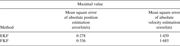
The performance of position estimation and velocity estimation based on EKF and PKF, achieved by Monte Carlo simulation experiment, is given in Figures 6 to 9. The mean square errors of position estimation error on the three axes based on the two algorithms are shown in Figure 6. The mean square errors of velocity estimation error on the three axes based on the two algorithms are shown in Figure 7. The mean square errors of absolute position estimation error based on the two algorithms are shown in Figure 8. The mean square errors of absolute velocity estimation error based on the two algorithms are shown in Figure 9. Considering that the mean square errors of position estimation error based on PKF gradually become stable after 2000 s, simulation data after 4000 s are selected for statistical analysis. The maximal mean square errors of position estimation errors on the three axes are shown in Table 1. The maximal mean square errors of velocity estimation error on the three axes are shown in Table 2. The maximal mean square errors of absolute position estimation error and absolute velocity estimation error are shown in Table 3.
Figure 6. Mean square errors of position estimation error.
Figure 7. Mean square errors of velocity estimation error.
Figure 8. Mean square error of absolute position estimation error.
Figure 9. Mean square error of absolute velocity estimation error.
Table 1. Maximal mean square errors of position estimation error.

Table 2. Maximal mean square errors of velocity estimation error.

Table 3. Maximal mean square error of absolute position, absolute velocity estimation error.
Figure 6 shows that the estimation errors based on PKF converge more slowly than those based on EKF. However, the estimation accuracies of position on the three axes based on the two algorithms are almost identical in the stable stage. Figure 7 shows that the trends of velocity estimation errors on the three axes based on PKF are similar to that based on EKF. Figure 8 shows that the estimation accuracies of absolute position based on the two algorithms are alike in stable stage, and both of them are less than 2 m. Figure 9 shows that the trends of absolute velocity estimation errors based on PKF and EKF are alike. Table 1 shows that the mean square errors of position estimation errors on the three axes based on PKF are all less than 3 m. The mean square errors of position estimation errors on the three axes based on PKF are larger than that based on EKF, but the differences between them are smaller than 0·5 m. Table 2 shows that the differences between mean square errors of velocity estimation errors on the three axes based on the two algorithms are all less than 0·1 m/s. Table 3 shows that the maximal mean square errors of absolute position based on PKF and EKF are 1·685 m and 1·439 m respectively, and the difference between them is less than 0·3 m. Besides, the maximal mean square errors of absolute velocity based on PKF and EKF in Table 3 are 0·336 m/s and 0·278 m/s respectively, and the difference between them is less than 0·1 m/s. These indicate that the estimation accuracies of position and velocity based on the two algorithms are alike, and the estimation accuracy based on PKF is slightly lower than that based on EKF. The reason for the results is that in order to decrease the calculation quantity of the PKF navigation algorithm, a number of the non-zero n-mode singular values are discarded for a decreasing number of vertices in the PLDIs model, and the compromise between computational complexity and modelling accuracy is realised. As a result, the PLDIs model is an approximate model of original nonlinear estimation error system, rather than a fully accurate model.
In conclusion, the estimation accuracy of position and velocity based on PKF navigation algorithm is equivalent to that based on EKF.
5. CONCLUSION
With the aim of improving the poor real-time performance of nonlinear filtering algorithms applied to spacecraft autonomous navigation, a PKF navigation algorithm is proposed in this paper. This method is based on the fact that the spacecraft autonomous navigation estimation error system can be modelled as a Polytopic Linear Differential Inclusion (PLDI) model, and the position and velocity of spacecraft can be estimated by combining multi-model Kalman filtering with data fusion. Compared with EKF, PKF navigation algorithm does not need to update the Jacobian matrix online and the algorithm design is simpler. The simulation results show that the PKF navigation algorithm has a good navigation performance and state estimation accuracy is similar to EKF. The PKF navigation algorithm simplifies the design of autonomous navigation algorithm, and has a simple online calculation. It is also relatively easy to implement. As a result, the PKF navigation algorithm has a better performance than EKF when applied in spacecraft autonomous navigation.
ACKNOWLEDGMENTS
This work was supported by National Natural Science Foundation of China (Grant No. 11372034) and Basic Research Foundation of Beijing Institute of Technology (No. 20130642010).