


1. INTRODUCTION
The primary objective of a satellite's navigation system is to determine, within a prescribed level of accuracy, its inertial position and velocity in space using on board measurements relating the satellite's position with respect to either the Earth or other navigation landmarks. The most common measurement types for a navigation system, as with inertial navigation systems, are the angles with reference to known landmarks, which are the relative azimuth and elevation indicating the direction of a known landmark from the satellite's reference or origin. Early solutions to this problem (see for example Wright, Reference Wright1981; Upadhyay et al., Reference Upadhyay, Cotterill and Deaton1993; Bisnath and Langely, Reference Bisnath and Langely1999) involved the use of ranging or the Global Positioning System (GPS) which is equivalent to ranging the satellite from known landmarks in space. However, in the case of deep space missions or at altitudes well over the altitude of the GPS satellites, GPS data is generally unavailable or imprecise. Thus one cannot assume that this is available. Sometimes alternate information is available that facilitates the determination of the satellite's orbit (Hajiyev and Ata, Reference Hajiyev and Ata2011). However when no ranging information is available the spacecraft must rely purely on angle measurement from landmarks that are quite distant such as the Sun and the Moon. In such situations, the spacecraft's navigation system may be considered to be autonomous. Autonomous navigation was investigated by Tuckness and Young (Reference Tuckness and Young1995) and by Long et al. (Reference Long, Leung, Folta and Gramling2000), but these generally involved other measurements such as the Doppler velocity and measurements from auxiliary landmarks. Orbit determination based on only precise angle measurement is a classical problem addressed by Laplace (Reference Laplace1780) and Gauss (Reference Gauss and Davis1809). However they had assumed precise measurements. The question of estimating the orbit from imprecise or noisy measurements was only addressed after the development of the Kalman filter and its extension to non-linear systems by Julier et al. (Reference Julier, Uhlmann and Durrant-Whyte1995; Reference Julier, Uhlmann and Durrant-Whyte2000) and Julier and Uhlmann (Reference Julier and Uhlmann2004). Ceccarelli et al. (Reference Ceccarelli, Garulli, Giannitrapani, Leomanni and Scortecci2007) applied the Unscented Kalman Filter (UKF) to the problem of spacecraft localisation using only angle measurements. Giannitrapani et al. (Reference Giannitrapani, Ceccarelli, Scortecci and Garulli2011) presented a comparison of Extended Kalman Filter (EKF) and UKF for spacecraft localisation via angle measurements.
In this paper, we consider the joint estimation of the position of a spacecraft and debris in Earth orbit to achieve spacecraft localisation based on angular measurements and precise measurements of the debris relative to the spacecraft. The dynamic model of the spacecraft caters for several perturbing effects, such as Earth and Moon gravitational field asymmetry and the Earth's oblateness effect. The Moon's position is assumed to be accurately known for the purposes of simulation from published Jet Propulsion Laboratory (JPL) ephemerides. The measurement process is based on the elevation and azimuth of the Moon and the Sun with respect to the spacecraft reference system. Range measurements are not assumed to be available. Position and velocity of the spacecraft are estimated by using the UKF. The performance of the filters are evaluated on an example of a deep space Earth-orbiting satellite and it is shown that the estimates of position and velocity components track the corresponding simulated position and velocity components.
2. DYNAMIC MODELLING OF SPACECRAFT AND DEBRIS
The three-body problem describes the motion of three bodies under mutual gravitational attraction. The problem may be laid out in a similar manner to the two-body problem. Equation (1) may be used to describe the force of gravity
 $\vec{F}_{g}$
, acting on one body due to the mutual attraction of two bodies where m
1 is the mass of the first body, m
2 is the mass of the second body, G is the universal gravitation constant and
$\vec{F}_{g}$
, acting on one body due to the mutual attraction of two bodies where m
1 is the mass of the first body, m
2 is the mass of the second body, G is the universal gravitation constant and
 $\vec{r}$
is the position vector of the second body relative to the first.
$\vec{r}$
is the position vector of the second body relative to the first.
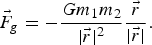 $$\vec{F}_g =-{\displaystyle{Gm_1 m_2} \over {\vert \vec{r} \vert ^2}} {\displaystyle{\vec{r}} \over {\vert \vec{r} \vert }}.$$
Equation (2) describes the force of gravity acting on one body, m 1, due to the mutual attraction of all three bodies:
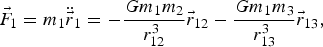 $$\vec{F}_1 =m_1 \ddot{\vec{r}}_1 =-{\displaystyle{Gm_1 m_2} \over {r_{12}^3}} \vec{r}_{12} -{\displaystyle{Gm_1 m_3} \over{r_{13}^3}}\vec{r}_{13},$$
where
 $\vec{r}_{1}$
is the position vector of the first body with respect to the origin,
$\vec{r}_{1}$
is the position vector of the first body with respect to the origin,
 $\vec{r}_{12}$
is the relative position vector of the second body with respect to the first, and
$\vec{r}_{12}$
is the relative position vector of the second body with respect to the first, and
 $\vec{r}_{13} $
is the relative position vector of the third body with respect to the first. The masses of the second and third bodies are m
2 and m
3 respectively.
$\vec{r}_{13} $
is the relative position vector of the third body with respect to the first. The masses of the second and third bodies are m
2 and m
3 respectively.
In the case of a satellite in orbit about the Earth under the influence of the Moon, the two primary masses move in two-body motion about each other, and the satellite is significantly affected by both masses. In this case, Equation (2) may be used to derive the following relationship for the satellite's acceleration:
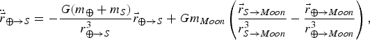 $$\ddot{\vec{r}}_{\oplus \to S} =- {\displaystyle{G\lpar m_\oplus +m_S \rpar } \over{r_{\oplus \to S}^3}} \vec{r}_{\oplus \to S} + Gm_{{Moon}} \left( {\displaystyle{\vec{r}_{S\to Moon}} \over {r_{S\to {Moon}}^3}}- {\displaystyle{\vec{r}_{\oplus \to {Moon}}} \over {r_{\oplus \to {Moon}}^3}}\right),$$
 $$\ddot{\vec{r}}_{\oplus \to S} =-G\lpar m_\oplus +m_S \rpar {\displaystyle{\vec{r}_{\oplus \to S}} \over {r_{\oplus \to S}^3}} +Gm_{{Moon}} \left({\displaystyle{\vec{r}_{\oplus \to {Moon}} -\vec{r}_{\oplus \to S}} \over {\vert \vec{r}_{\oplus \to {Moon}} -\vec{r}_{\oplus \to S}\vert^3}}-{\displaystyle{\vec{r}_{\oplus \to {Moon}}} \over {r_{\oplus \to {Moon}}^3}}\right),$$
where the subscripts ⊕, Moon, and S refer to the Earth, the Moon, and the satellite, respectively, and the subscript ⊕→S indicates a vector that originates at the Earth and ends at the satellite. In general,
 $\vec{r}$
refers to a position vector, r refers to its magnitude and m the mass of a planetary body or satellite. The first term in Equation (3) is the familiar two-body equation of motion; the second term is the third-body perturbation and it is composed of two parts. The left part of the second term is referred to as the direct effect because it is the contribution of the Moon's gravity acting on the spacecraft only; the right part of the second term is referred to as the indirect effect because it is the contribution of the Moon's gravity acting on the Earth, and thus indirectly influencing the spacecraft (Vallado, Reference Vallado2001). The second term must be subtracted from the first, as we are considering here the motion of the satellite relative to the Earth. The total third-body effect is generally very small either when the spacecraft is very close to the Earth or when the third body is very far away from the Earth-spacecraft two-body system. An equation similar to Equation (4) may be written for the debris position and this equation is completely uncoupled from the spacecraft's dynamics.
$\vec{r}$
refers to a position vector, r refers to its magnitude and m the mass of a planetary body or satellite. The first term in Equation (3) is the familiar two-body equation of motion; the second term is the third-body perturbation and it is composed of two parts. The left part of the second term is referred to as the direct effect because it is the contribution of the Moon's gravity acting on the spacecraft only; the right part of the second term is referred to as the indirect effect because it is the contribution of the Moon's gravity acting on the Earth, and thus indirectly influencing the spacecraft (Vallado, Reference Vallado2001). The second term must be subtracted from the first, as we are considering here the motion of the satellite relative to the Earth. The total third-body effect is generally very small either when the spacecraft is very close to the Earth or when the third body is very far away from the Earth-spacecraft two-body system. An equation similar to Equation (4) may be written for the debris position and this equation is completely uncoupled from the spacecraft's dynamics.
One of the difficulties experienced in integrating Equation (3) is the fact that the relative position vectors
 $\vec{r}_{S\to {Moon}} $
and
$\vec{r}_{S\to {Moon}} $
and
 $\vec{r}_{\oplus \to {Moon}} $
are about the same order of magnitude. Thus, as we are subtracting one term from the other, there is a loss of accuracy and precision. The solution to this problem is to non-dimensionalise the distances so as to accentuate the difference between the terms
$\vec{r}_{\oplus \to {Moon}} $
are about the same order of magnitude. Thus, as we are subtracting one term from the other, there is a loss of accuracy and precision. The solution to this problem is to non-dimensionalise the distances so as to accentuate the difference between the terms
 $\vec{r}_{S\to {Moon}} $
and
$\vec{r}_{S\to {Moon}} $
and
 $\vec{r}_{\oplus \to {Moon}} $
in the direct and indirect effects contributing to Equation (3). While there is no need to “maximise” this difference in the strict sense of the term, it is indeed useful to choose a unit of distance that will heighten the difference between the terms
$\vec{r}_{\oplus \to {Moon}} $
in the direct and indirect effects contributing to Equation (3). While there is no need to “maximise” this difference in the strict sense of the term, it is indeed useful to choose a unit of distance that will heighten the difference between the terms
 $\vec{r}_{S\to {Moon}} $
and
$\vec{r}_{S\to {Moon}} $
and
 $\vec{r}_{\oplus \to {Moon}}$
, and thus allow for the accurate evaluation of the total acceleration of either the satellite or the debris. Another trick that could be adopted if necessary is to use truncated series expansions of terms like
$\vec{r}_{\oplus \to {Moon}}$
, and thus allow for the accurate evaluation of the total acceleration of either the satellite or the debris. Another trick that could be adopted if necessary is to use truncated series expansions of terms like
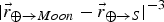 $\vert \vec{r}_{\oplus \to {Moon}} -\vec{r}_{\oplus \to S}\vert ^{-3}$
. However, when this is done, the residual terms must also be estimated and included in some form whenever necessary. Any attempts to non-dimensionalise the distances must be accompanied by a matching non-dimensionalisation of the unit of time as otherwise the equations will be too unbalanced and result in numerical difficulties. Another approach is to use Battin's (Reference Battin1987) scalar function
$\vert \vec{r}_{\oplus \to {Moon}} -\vec{r}_{\oplus \to S}\vert ^{-3}$
. However, when this is done, the residual terms must also be estimated and included in some form whenever necessary. Any attempts to non-dimensionalise the distances must be accompanied by a matching non-dimensionalisation of the unit of time as otherwise the equations will be too unbalanced and result in numerical difficulties. Another approach is to use Battin's (Reference Battin1987) scalar function
 $\lpar \,f(q)=\lpar \lpar q+1\rpar^{3}-1\rpar /\lpar \lpar q+1\rpar^{3/2}+1\rpar \rpar $
to represent these vector difference functions accurately. In this work we have adopted a scalar function similar to Battin's (Reference Battin1987) to estimate the Sun's third body effect. For our purposes therefore we also choose the unit of time as one day while the unit of distance is chosen to be the radius of the geostationary circular orbit. All calculations are performed by referring to Julian days based on Universal Time (UT), as it is then easy to convert to Barycentric Dynamical Time (TDB) whenever necessary. Conversions from TDB to UT are generally relatively harder.
$\lpar \,f(q)=\lpar \lpar q+1\rpar^{3}-1\rpar /\lpar \lpar q+1\rpar^{3/2}+1\rpar \rpar $
to represent these vector difference functions accurately. In this work we have adopted a scalar function similar to Battin's (Reference Battin1987) to estimate the Sun's third body effect. For our purposes therefore we also choose the unit of time as one day while the unit of distance is chosen to be the radius of the geostationary circular orbit. All calculations are performed by referring to Julian days based on Universal Time (UT), as it is then easy to convert to Barycentric Dynamical Time (TDB) whenever necessary. Conversions from TDB to UT are generally relatively harder.
If one includes the effect of the second zonal harmonic coefficient J 2, in the expansion of the Earth's gravitational potential in terms of a series of Legendre polynomials, the equations must be modified. The other harmonics are of the order of 10−3 less than the J 2 effect and could be neglected. The additional acceleration due to the J 2 effect due to the Earth's oblateness can be expressed as,
 $$\vec{a}_{J_2} =-{\displaystyle{3J_2} \over {2}} {\displaystyle{\mu_e} \over {\vec{r}^2}} \left({\displaystyle{R_e} \over {\vert \vec{r}\vert }}\right)^2 \left[ \lpar 1-3z^2/ \vec{r}^2\rpar x \quad \lpar 1-3z^2/ \vec{r}^2\rpar y \quad \lpar 3-3z^2/ \vec{r}^2\rpar z\right]^T {\displaystyle{1} \over {\vert \vec{r}\vert }},$$
where
 $$\vec{r}=\vec{r}_{\oplus \to S} =\left[ x \quad y \quad z \right],\quad J_2 =1{\cdot}082629\times 10^{-3},\quad \mu_e =G\lpar m_\oplus +m_S \rpar \approx Gm_\oplus ,$$
and R e is the mean equatorial radius of the Earth.
After the J 2 effect, the next important term is the C 22 term in the expansion of the Earth's gravitational potential which is a constant associated with the sectorial harmonics (zero potential along meridians of longitude). We also include explicitly the most significant of the sectorial and the tesseral harmonics (zero potentials along parallels of latitude). Since the model considers only the most relevant gravitational terms, there are several other sources of perturbing accelerations arising from the variations of the Earth's and the Moon's gravitational field which are modelled as two independent noise sources. Again, a similar perturbing acceleration term may be written to capture the oblateness effect on the debris mass. Other sources of perturbation accelerations due to the atmospheric drag and lift, third-body gravitational perturbations due to the Sun as well as secondary effects of the Earth and Moon, solar radiation pressure, albedo radiation pressure of the central body, thermal radiation pressure of the central body, forces due to the tides and tidal variations including the solid Earth tides, ocean tides and the rotational deformation of the Earth, forces due to the Earth's magnetic field and its variations and other control forces and other perturbations that have not been accounted for, are modelled as a third independent white noise source. (For spacecraft operating below 600–800 km we could introduce an aerodynamic model so as to reduce the perturbation acceleration error due to the presence of aerodynamic forces to well below the perturbation acceleration due to oblateness.) Thus the use of an independent white noise model is completely justified. The spacecraft's propulsion system which generates the thrust and other control forces is modelled independently. Thus the satellite and debris each experience the perturbing accelerations from three independent noise sources.
3. THE POSITION OF THE MOON
Knowing the precise position coordinates of the Moon is vital for the success of the simulation of the orbit of an Earth orbiting satellite and consequently important for validating the orbit estimation methodology. The JPL Ephemeris model based on the JPL Planetary and Lunar Ephemerides, “DE405/LE405,” which was constructed in 1998 (Standish, Reference Standish1998) is an excellent source for this. The model uses the International Celestial Reference Frame as its coordinate system. The model included ephemerides of the positions and velocities of the Sun, the Moon, the ephemerides for a pair of nutation angles and the three physical libration angles for the Moon as well the four terrestrial planets, the four gas-giant planets and the Pluto/Charon system. According to Standish, the entire ephemeris system of DE405 for the Moon and the inner planets is accurate to approximately 0·001 arcsecond which was verified by the 0·001-arcsecond error in the ephemeris upon the arrival of the Pathfinder spacecraft at Mars in July 1997 (Standish, Reference Standish1998; Standish and Williams, Reference Standish, Williams, Urban and Seidelmann2012). In 2008 the DE421 ephemeris was generated (Folkner et al., Reference Folkner, Williams and Boggs2008; Williams et al., Reference Williams, Boggs and Folkner2008). The planetary and lunar ephemeris DE430/DE431 described by Folkner et al. (Reference Folkner, Williams, Boggs, Park and Kuchynka2014) is provided for missions to the Moon, Mars and other solar system bodies. The lunar orbit and surface coordinates of the planetary ephemerides corresponding to DE430/DE431 can be obtained directly from a JPL website. High precision ephemerides for Solar System bodies are available online using JPL's HORIZONS system (http://ssd.jpl.nasa.gov/?ephemerides). The JPL HORIZONS online solar system data and ephemeris computation service provides access to key solar system data and flexible production of highly accurate ephemerides for solar system objects (713552 asteroids, 3414 comets, 178 planetary satellites, 8 planets, the Sun, the Earth-Sun unstable Lagrange points L1, L2, selected spacecraft, and system barycentres). HORIZONS is provided by the Solar System Dynamics Group of the Jet Propulsion Laboratory. Along with the planetary orbits, the orbit and physical librations of the Moon are regularly updated. According to the website, the planetary ephemerides that are available using JPL's HORIZONS system provide the accuracy desired for most applications. HORIZONS uses the long-term DE406/LE406 for the Moon. The JPL DE406/LE406 extended ephemeris covers the interval from 3000 B.C. to A.D. 3000. This ephemeris is identical to the shorter DE405 in the sense that it is the same data-fit (solution) and the same numerical integration as DE405. However, it has been stored with slightly less accuracy to reduce its size. For the Moon, DE406 recovers the original integrator state to within one metre. In this paper we have used the HORIZONS system to obtain the position coordinates of the Moon and considering the above discussion we are justified in assuming that we know the Moon's position exactly. Although the HORIZONS system will be sufficient for the vast majority of ephemeris applications, the JPL's Planetary and Lunar Ephemerides related files (e.g. DE405, DE406, DE430 and DE431) are also available.
For purposes of rapidly testing the estimation methodology, Simpson (Reference Simpson1999) has provided a functional approximation which is very fast to evaluate (but not very accurate for actual estimation applications).
4. THE MEASUREMENTS
It is assumed that the spacecraft is equipped with sensors that provide angular measurements of azimuth and elevation of Moon and Sun, with respect to a local reference system centred at the spacecraft and aligned to Earth Centred Inertial (ECI), (it is assumed that the attitude of the spacecraft is known). The Sun directional measurements can be done using Micro-Electromechanical Systems (MEMS) sensors of the type developed by Liebe et al. (Reference Liebe, Mobasser, Bae, Wrigley, Schroeder and Howard2002). To measure the direction of the Moon one could use a camera or a magnetometer, to measure strength and direction of the Moon's magnetic field. One could also use an accelerometer to measure the direction of the Earth's gravity vector, although in the first instance it is assumed that only the Moon and Sun measurements are available. It is also assumed that the precise vector of the position of the debris relative to the satellite can be accurately measured. This can be done by accurate radar or laser ranging instruments on board the spacecraft.
5. THE NOISE SOURCES
We are now in a position to discuss the nature and statistics of the process and measurement noise sources. Because we have included the Earth's gravitational potential effects in our computations, above an altitude of 800 km, the magnitude of the perturbations must be less than one thousandth of the magnitude of the perturbation acceleration due to the Earth's gravitational potential effects. Perturbations due to the Moon's gravitational field are assumed to be of the same order when the spacecraft is in the Moon's sphere of influence but much less when within the Earth's sphere of influence. Thus the standard deviation is assumed to be inversely proportional to the square of the distance from the Earth in the first case and the Moon in the second and that they are approximately of similar order at a distance equal to the radius of the geostationary circular orbit. The magnitudes are evaluated by evaluating the Earth's gravitational potential perturbation acceleration at a distance equal to the radius of the geostationary circular orbit. Furthermore we assume that the magnitude of error in the distance of the Moon is less than a metre. Thus we are able to model the process noise reasonably accurately.
In our dynamic model we have already included the central force acceleration, gravitational acceleration due to oblateness of the central body and the Moon's primary acceleration contribution. Thus the noise statistics were determined by meticulously estimating the Sun's central force acceleration, Earth's other gravitational accelerations, the solar radiation pressure acceleration, the Earth's tidal acceleration, the ocean's tidal acceleration, the atmospheric drag acceleration, the acceleration due to general relativity and the acceleration due to the other planets’ central forces. Thus both the process and measurement noise statistics can also be modelled with some certainty. However it must be assumed that the measurement of the relative position vector of the debris is significantly more accurate (between one and two orders of magnitude lower error) than the angle measurements of the Sun and Moon, from the spacecraft.
6. THE UNSCENTED KALMAN FILTERS
The mixing filter is implemented as an unscented Kalman filter. The basic unscented Kalman filter is identical to the filter implemented in Vepa and Zhahir (Reference Vepa and Zhahir2011).
Consider a random variable
 ${\bf w}$
with dimension L which is going through the nonlinear transformation,
${\bf w}$
with dimension L which is going through the nonlinear transformation,
 ${\bf y} = {\bf f}({\bf w})$
. The initial conditions are that
${\bf y} = {\bf f}({\bf w})$
. The initial conditions are that
 ${\bf w}$
has a mean
${\bf w}$
has a mean
 $\widebar{{\bf w}}$
and a covariance
$\widebar{{\bf w}}$
and a covariance
 ${\bf P}_{ww}$
. To calculate the statistics of
${\bf P}_{ww}$
. To calculate the statistics of
 ${\bf y}$
, a matrix χ of 2L+1 sigma vectors is formed. We have chosen to use the scaled unscented transformation proposed by Julier (Reference Julier2002), as this transformation gives one the added flexibility of scaling the sigma points to ensure that the covariance matrices are always positive definite.
${\bf y}$
, a matrix χ of 2L+1 sigma vectors is formed. We have chosen to use the scaled unscented transformation proposed by Julier (Reference Julier2002), as this transformation gives one the added flexibility of scaling the sigma points to ensure that the covariance matrices are always positive definite.
Given a general discrete time nonlinear dynamic system in the form,
 $${\bf x}_{k+1} ={\bf f}_k \lpar {\bf x}_k, {\bf u}_k\rpar + {\bf w}_k, \quad {\bf y}_k = {\bf h}_k \lpar {\bf x}_k\rpar + {\bf v}_k$$
where
 ${\bf x}_{k} \in R^{n}$
is the state vector,
${\bf x}_{k} \in R^{n}$
is the state vector,
 ${\bf u}_{k} \in R^{r}$
is the known input vector,
${\bf u}_{k} \in R^{r}$
is the known input vector,
 ${\bf y}_{k} \in R^{m}$
is the output vector at time k.
${\bf y}_{k} \in R^{m}$
is the output vector at time k.
 ${\bf w}_{k}$
and
${\bf w}_{k}$
and
 ${\bf v}_{k}$
are, respectively, the disturbance or process noise and sensor noise vectors, which are assumed to be Gaussian white noise with zero mean. Furthermore
${\bf v}_{k}$
are, respectively, the disturbance or process noise and sensor noise vectors, which are assumed to be Gaussian white noise with zero mean. Furthermore
 ${\bf Q}_{k} $
and
${\bf Q}_{k} $
and
 ${\bf R}_{k} $
are assumed to be the covariance matrices of the process noise sequence,
${\bf R}_{k} $
are assumed to be the covariance matrices of the process noise sequence,
 ${\bf w}_{{\bf k}}$
and the measurement noise sequence,
${\bf w}_{{\bf k}}$
and the measurement noise sequence,
 ${\bf v}_{{\bf k}}$
respectively. The unscented transformations of the states corresponding to the functions
${\bf v}_{{\bf k}}$
respectively. The unscented transformations of the states corresponding to the functions
 ${\bf f}_{k} \lpar {\bf x}_{k}, {\bf u}_{k} \rpar $
and
${\bf f}_{k} \lpar {\bf x}_{k}, {\bf u}_{k} \rpar $
and
 ${\bf h}_{k} \lpar {\bf x}_{k} \rpar $
are denoted respectively as,
${\bf h}_{k} \lpar {\bf x}_{k} \rpar $
are denoted respectively as,
 $${\bf f}_k^{UT} = {\bf f}_k^{UT} \lpar {\bf x}_k, {\bf u}_k\rpar , \quad {\bf h}_k^{UT} = {\bf h}_k^{UT} \lpar {\bf x}_k \rpar $$
while the transformed covariance matrices and cross-covariance are respectively denoted as,
 $${\bf P}_k^{ff} = {\bf P}_k^{ff} \lpar \hat{{\bf x}}_k, {\bf u}_k\rpar , \quad {\bf P}_k^{hh-} = {\bf P}_k^{hh} \lpar \hat{{\bf x}}_k^- \rpar $$
and
 $${\bf P}_k^{xh-} = {\bf P}_k^{xh-} \lpar \hat{{\bf x}}_k^-, {\bf u}_k \rpar .$$
The UKF estimator can then be expressed in a compact form. The state time-update equation, the propagated covariance, the Kalman gain
 ${\bf K}_{k}$
, the state estimate
${\bf K}_{k}$
, the state estimate
 $\hat{{\bf x}}_{k}$
and the updated covariance
$\hat{{\bf x}}_{k}$
and the updated covariance
 $\hat{{\bf P}}_{{\bf k}}$
are respectively given by,
$\hat{{\bf P}}_{{\bf k}}$
are respectively given by,
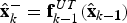 $$ \hat{{\bf x}}_k^- = {\bf f}_{k-1}^{UT} \lpar \hat{{\bf x}}_{k-{\bf 1}}\rpar $$
 $$ \hat{{\bf P}}_k^- = {\bf P}_{k-1}^{ff} + {\bf Q}_{k-1} $$
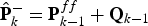
 $$ {\bf K}_k = \hat{{\bf P}}_k^{xh-} \lpar \hat{{\bf P}}_k^{hh-} + {\bf R}_k\rpar ^{-1} $$
 $$ \hat{{\bf x}}_k = \hat{{\bf x}}_k^- + {\bf K}_k \lfloor{\bf z}_k - {\bf h}_k^{UT} \lpar \hat{{\bf x}}_k^- \rpar \rfloor $$
 $$ \hat{{\bf P}}_{{\bf k}} = \hat{{\bf P}}_k^- - {\bf K}_k \lpar \hat{{\bf P}}_k^{hh-} + {\bf R}_k \rpar ^{-1} {\bf K}_k^T. $$
Equations (10a)–(10e) are in the same form as the traditional Kalman filter and the extended Kalman filter. Thus higher order non-linear models capturing significant aspects of the dynamics may be employed to ensure that the Kalman filter algorithm can be implemented to effectively estimate the states in practice.
In order to employ the UKF when precise statistics of the process and measurement noise vectors are not available, the adaptive filter method proposed by Song et al. (Reference Song, Qi and Han2006) may be used to estimate the orbital states. The covariance matrices of measurement residuals are recursively updated in the UKF. The estimated measurement noise covariance matrices
 $\hat{{\bf R}}_{k}$
, in the case of the UKF, may be expressed as:
$\hat{{\bf R}}_{k}$
, in the case of the UKF, may be expressed as:
 $$\hat{{\bf R}}_k = {\bf C}_r^{k,\,N} + \hat{{\bf P}}_k^{hh}$$
where,
 ${\bf C}_{r}^{k,\,N} $
is defined in terms of the sample size N and the residual
${\bf C}_{r}^{k,\,N} $
is defined in terms of the sample size N and the residual
 ${\bf r}_{k}$
as,
${\bf r}_{k}$
as,
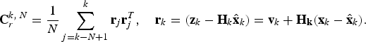 $${\bf C}_r^{k,\,N} = {\displaystyle {1} \over {N}} \sum_{j=k-N+1}^k {\bf r}_j {\bf r}_j^T, \quad {\bf r}_k =\lpar {\bf z}_k - {\bf H}_k \hat{{\bf x}}_k \rpar = {\bf v}_k + {\bf H}_{{\bf k}} \lpar {\bf x}_k - \hat{{\bf x}}_k\rpar .$$
Equation (11) involves the further computation of
 $\hat{{\bf P}}_{k}^{hh}$
, by applying the unscented nonlinear transformation,
$\hat{{\bf P}}_{k}^{hh}$
, by applying the unscented nonlinear transformation,
 ${\bf h}_{k}^{UT} \lpar \hat{{\bf x}}_{k}\rpar $
to the state estimate,
${\bf h}_{k}^{UT} \lpar \hat{{\bf x}}_{k}\rpar $
to the state estimate,
 $\hat{{\bf x}}_{k}$
. The measurement noise covariance may be updated in principle by employing Equation (11). The nonlinear relationships between the covariance matrices also suggests that the update of
$\hat{{\bf x}}_{k}$
. The measurement noise covariance may be updated in principle by employing Equation (11). The nonlinear relationships between the covariance matrices also suggests that the update of
 ${\bf R}_{k}$
, if need be, could be done by employing the covariance of the residual. However in this work the need for adaptation did not arise.
${\bf R}_{k}$
, if need be, could be done by employing the covariance of the residual. However in this work the need for adaptation did not arise.
7. TYPICAL SIMULATIONS AND RESULTS
The initial position and velocity of the satellite are obtained from the classical orbital elements defined in Table 1. From these orbital elements the initial position and velocity vector of the satellite and debris are obtained. The numerical integration was performed using the Runge-Kutta Dormand-Prince 4(5) and Runge-Kutta-Fehlberg 7(8) algorithms (Dormand and Prince, Reference Dormand and Prince1980; Fehlberg, Reference Fehlberg1969). The results obtained in the latter case were not different from the former, although the former case always took significantly more time. So only the results of the former will be shown. The non-dimensionalizing distance was chosen to be r sc =35786 km and unit of time was t sc =86400 sec.
Table 1. Orbital elements defining the initial position of the Satellite and Debris.
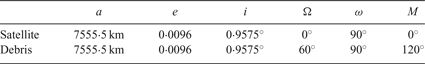
Figure 1 shows the error in the Moon's position estimated by using data from the JPL HORIZONS site at time intervals of one hour compared with data obtained at time intervals of one minute. In the numerical integration of the equations of motion the data from the JPL HORIZONS site at time intervals of one hour was used. The Moon's position at any time was found by interpolation. The time step for the integration of the satellite's and debris’ equations was chosen to be
 $\Delta t=0{\cdot}0005 t_{sc}$
, which is slightly over two-thirds of a minute.
$\Delta t=0{\cdot}0005 t_{sc}$
, which is slightly over two-thirds of a minute.

Figure 1. Moon coordinates and distance error in metres.
Figure 2 shows the errors in the estimates of the satellite's position coordinates over a day. At the specific time instances the errors could be as high as 1 km in the y direction and 0·3 km in the z direction. Figure 3 shows the corresponding errors in the estimates of the satellite's velocity components over a day. An interesting feature of the errors is that they are periodic although not sinsusoidal and can be completely eliminated by further filtering using a moving average or a suitable low pass filter.

Figure 2. Errors in metres, in the estimates of the satellite's position coordinates over a day.

Figure 3. Errors in metres/s, in the estimates of the satellite's velocity components over a day.
Figure 4 shows the errors in the estimates of the debris’ position coordinates over a day. Figure 5 shows the corresponding errors in the estimates of the debris’ velocity components over a day. The errors in Figure 4 are similar to those in Figure 2 with the exception that the errors in the z direction are relatively smaller while those in the x and y directions are much higher.

Figure 4. Errors in metres, in the estimates of the debris’ position coordinates over a day.

Figure 5. Errors in metres/s, in the estimates of the debris’ velocity components over a day.
8. CONCLUSIONS
The above simulations indicate quite clearly that the errors are periodic and therefore can be periodically equal to zero. Although the errors are periodic they are not sinusoidal and consequently can be quite large at certain times. If these periodic errors are “ignored” or eliminated by filtering, the error in the position of the satellite is less than 50 m. If one includes measurements of the direction of the Earth's gravity vector, there is a dramatic reduction in error. Yet this case was deliberately not considered as in deep space missions this would not represent a realistic scenario. The orders of magnitude of the errors obtained were not too different from those obtained by Ceccarelli et al. (Reference Ceccarelli, Garulli, Giannitrapani, Leomanni and Scortecci2007) although it was difficult to compare as Ceccarelli et al. (Reference Ceccarelli, Garulli, Giannitrapani, Leomanni and Scortecci2007) obtained their position errors in units of kilometres. Yet we did not use measurements of the Earth's azimuth and elevation. The current work is focussed on reducing these errors significantly by including one or more star sensors especially at those times where there is significant degradation of the accuracy of the estimate. Once this is achieved it is expected to extend this work to tracking multiple objects of debris. The ability to accurately track space debris or even other planetary objects approaching the Earth is a problem of some significance that is receiving the attention of research groups worldwide.
We are currently studying the feasibility of joint estimation of both an Earth-orbiting spacecraft's position as well as the position of an asteroid (or any Sun-orbiting debris that can be physically sighted and tracked by an on board telescope). Our focus has been on asteroids such as Eros which is considered to be a near-Earth asteroid. Even clouds of unstable or potentially unstable debris accompanying an asteroid can pose a serious threat to the Earth's environment. The dynamic model of the spacecraft includes perturbing effects due to gravitation of multiple planetary bodies. As for the asteroid, we assume it is orbiting the Sun and that it is also influenced by Mars and the Earth. Both for the satellite and for the asteroid we can show that other perturbation effects are of several orders of magnitude smaller and can be assumed to contribute to the process noise disturbing the dynamics of the satellite or asteroid. However, we also assume that the position coordinates of the asteroid can be accurately measured relative to the spacecraft which is feasible only if one employs a laser-based system. Thus, by assuming suitable measurement noise statistics, we are seeking to successfully estimate the spacecraft's and asteroid's position as well as the position of any debris in the vicinity of either the satellite or the asteroid. The results obtained so far are extremely promising and this work is expected to published separately.


