


1. INTRODUCTION
Navigational error accounts for half the accidents and serious incidents in maritime transportation worldwide (DNV, 2013). These have increased significantly since the introduction of the Global Positioning System (GPS) and Electronic Chart Display and Information Systems (ECDIS) on most ships (1995–2002). While there is no direct evidence linking this directly with GPS and ECDIS, previous research (Boyes, Reference Boyes2013; Grant et al., Reference Grant, Williams and Basker2010) has suggested that navigators' over-reliance on GPS could be a cause.
Modern ships are highly automated, able to run with little human interaction with the ship's networked navigational and operational systems. Whilst they are extremely convenient, these features make them exceedingly vulnerable to cyber-attacks, including spoofing or the jamming of a ship's GPS system (CCICADA, 2015). The same document states that nowhere is the necessity of building greater resilience more apparent than in the large, modern ship.
Similar trends can be seen in Norwegian waters (Naevestad et al., Reference Naevestad, Caspersen, Hovi, Bjoernskau and Steinsland2014). Statistics do not specify the cause of the accidents that occur, but it is generally assumed that the main factors are the increase in foreign vessel traffic, the rapidly changing weather conditions, the dangerous nature of the narrow inshore waters, and the over-dependence on GPS in those conditions, which can lead to a false feeling of security. Any foreign flagged vessels exceeding 70 metres, or 50 metres if carrying hazardous or polluting cargo, need compulsory pilotage to pass through inshore water fairways (fjords). The compulsory pilotage requirement can be met by either employing a pilot or a navigator holding a Pilot Exemption Certificate - a theoretical and practical examination which includes knowledge of the waters and visual and radar navigation (The Norwegian Coastal Administration, 2016). Even with this experience, navigation is difficult and pilots tend to rely on GPS.
To address GPS accuracy in the fjords, the Norwegian Coastal Administration has established a network of 12 Differential GPS (DGPS) stations along the Norwegian coast. Each DGPS station (de facto reference station) calculates corrections using pseudorange measurements, which are then transmitted in the 283·5 kHz – 315 kHz frequency band, and can be received by vessels equipped with a DGPS radio receiver. The stated planar accuracy of the system, within the coverage area, is better than 10 metres (2 drms) and in reality an accuracy of 1–3 metres is expected (The Norwegian Coastal Administration, 2014). Use of DGPS is therefore crucial for high accuracy navigation in the demanding and narrow Norwegian straits.
Volpe (Reference Volpe2001) raised awareness of GPS vulnerability to intentional and unintentional interference. Since then a number of studies have addressed this, using GNSS simulators (Borio et al., Reference Borio, O'Driscoll and Fortuny2013; Mitch et al., Reference Mitch, Dougherty, Psiaki, Powell, O`Hanlon, Bhatti and Humphreys2011; Kuusniemi et al., Reference Kuusniemi, Airos, Bhuiyan and Kröger2012) or outdoor GPS jamming tests (in South Africa and Germany) (Niekerk and Combrinck, Reference Niekerk and Combrinck2012; Bauernfeind et al., Reference Bauernfeind, Kraus, Dötterböck and Eisfeller2011). The findings from these studies indicate that the combination of highly sensitive GPS receivers and the low signal strength of spaceborne GPS makes this navigation technology very vulnerable to jamming. The General Lighthouse Authorities of the United Kingdom and Ireland have also run a number of jamming trials close to the English shore (Grant et al., Reference Grant, Williams and Basker2010). Apart from intentional jamming, DGPS signals can also be disrupted by interference from other radio transmitters (unintentional jamming) and are limited in fjord areas, where the signals must pass over high terrain.
Currently, typical marine grade receivers are differential GPS L1 receivers (Grant et al., Reference Grant, Williams and Basker2010), most of which were installed several years ago and which will eventually need to be upgraded. With the decreasing cost of modern hardware, these replacements are likely to be multi-constellation or even multi-frequency receivers. The aim of this paper is to research the jamming vulnerability of the existing maritime receivers and to suggest the best update option. This leads to the following research question: Do multi-constellation/multi-frequency GNSS receivers offer any additional jamming resilience over the current GPS L1 or GLONASS G1 receivers?
This paper focuses on civilian traffic navigating close to the Norwegian shore, at the high northern latitudes, and using Norwegian Coastal Administration DGPS stations. To this end, dedicated jamming trials, addressing those conditions, have been conducted in the northern part of Norway, within the Polar Circle, identified as one of the more problematic areas.
The novelty of this work is a comparison of jamming resilience between different combinations of multi-constellation (American GPS and Russian GLONASS) and multi-frequency GNSS signals. Previous research has not addressed the usability of additional frequencies (L1, L2, G1, G2) or additional constellations for jamming resilience, especially at those latitudes.
This paper is organised as follows: Section 2 discusses the nature of radio frequency interference, Section 3 describes the trials conducted and shows a comparison of the modern GNSS receiver used in the trials with existing maritime receivers. Section 4 then discusses positioning accuracy and compares the jamming results between multiple frequencies (L1, L2, G1, G2) and constellations (American GPS and Russian GLONASS), Section 5 discusses how use of multiple frequencies and constellations can increase jamming resilience and finally Section 6 contains a summary and conclusions.
2. RADIO FREQUENCY INTERFERENCE ON THE GNSS SIGNAL (JAMMING)
Generally, multi-constellation DGPS receivers increase position reliability not the accuracy. For this a standard approach is to use multiple frequencies and a carrier-based solution (such as Real Time Kinematic (RTK)). The latter is more expensive, due to front-end complexity and proprietary algorithms needed to decode the GPS L2 signal. Hence the current industry standard is an increase in constellations not frequencies.
A typical jammer operates very close to GPS L1 central frequency. Figure 1 shows the frequency allocations for GPS (L1 and L2) and GLONASS (G1 and G2). The comparison graph also shows the modernised GLONASS G3 and GPS L5 bands, as well as the one used by the Galileo constellation. The primary frequencies, G1 and L1, are situated close to each other and a single broadband jammer can interfere with both the GPS and GLONASS primary frequencies.

Figure 1. GNSS Frequency allocation (Subirana et al., Reference Subirana, Juan Zornoza and Hernandez-Pajares2011).
Radio Frequency Interference (RFI) caused by the jammer can be pulsed or continuous. Continuous RFI can be classified by its bandwidth and is usually differentiated into broadband or narrowband (Kaplan and Hegarty, Reference Kaplan and Hegarty2006). This classification is relative to the GNSS band, and implies that a broadband RFI will have a bandwidth equal to, or greater than the GNSS band (2 MHz for the GPS Coarse/Acquisition (C/A)-code on L1) while the narrowband RFI will have a bandwidth narrower than GNSS.
Jones (Reference Jones2011) plotted theoretical values for different Continuous Wave (CW) broadband jammers, with power from 10 mW to 1 kW, which are shown in Figure 2. Jammer-to-Signal ratio (J/S), which is dependent on the spatial separation between receiver and interference, determines the amount of interference that receivers can handle and still be able to acquire or track the GNSS signal. Horizontal dashed lines show some typical receiver thresholds, indicating that a small 10 mW jammer is able to prevent acquisition of C/A code for distances less than 10 km.

Figure 2. The effect of various jammers on GPS receivers (Jones, Reference Jones2011).
Mitch et al. (Reference Mitch, Dougherty, Psiaki, Powell, O`Hanlon, Bhatti and Humphreys2011) tested 18 of the current, commercially available, handheld civilian GNSS jammers with regards to signal properties. Most of the jammers in this research transmit signals with bandwidths exceeding the 2 MHz civilian GPS C/A signals, and some of them have a bandwidth exceeding the 20 MHz P(Y) signal. The majority of the jamming signals were generated by frequency modulation of a CW signal with some sort of swept tone method to generate broadband interference and most of the jammers used linear chirp signals. Figure 3 shows the results of the analysis of a typical low powered jammer.

Figure 3. Signal characteristics for a group 1 jammer (Mitch et al., Reference Mitch, Dougherty, Psiaki, Powell, O`Hanlon, Bhatti and Humphreys2011).
Each sweep is for 9 microseconds and covers a range of about 14 MHz, which includes the civilian L1 band. The central frequency is the red horizontal line where the power was measured at 22 mW.
Carrier-to-noise power density ratio Signal to Noise Ratio (SNR) (signal strength) is the fundamental parameter for defining signal quality at the receiver (Hofmann-Wellenhof, Reference Hofmann-Wellenhof2008). SNR is defined as the bandwidth-independent index number, relating the carrier power to noise per 1 Hz bandwidth, which is expressed in dB-Hz.
Bauernfeind et al. (Reference Bauernfeind, Kraus, Dötterböck and Eisfeller2011) used the Galileo open-field Test Range in Germany to research the change in carrier-to noise (C/N0) of the GNSS signal, while jammed by widely available low-cost GNSS jammers, transmitting a chirp signal with a bandwidth of 11·8 MHz in the L1 band. The effective jammer power was -40 dBW (0·1 mW).
Figure 4 shows the results from the multi-frequency Ipex software GNSS receiver, as the distance to the jammer changes. The blue line in Figure 4 shows the recorded SNR degradation versus the theoretical curve (the red line). The measured curves follow the theoretical curves as long as the front end is not saturated with received jammer power, as is noticeable above the noise floor.

Figure 4. SNR for Ipex SW Receiver and the theoretical curve (Bauernfeind et al., Reference Bauernfeind, Kraus, Dötterböck and Eisfeller2011).
These results suggest that a typical jammer operates very close to the GPS L1 central frequency, which will affect GLONASS G1, yet should not affect GPS L2 or GLONASS G2 frequencies.
3. TRIAL DESCRIPTION
As discussed in the introduction, the trial's aim was to simulate civilian vessels using the Norwegian Coastal Administration DGPS stations and to expose them to jamming while navigating the inshore Norwegian waters at the high northern latitudes. To conduct these trials, jamming permission was obtained from the Norwegian Communications Authority, on the condition that no other vessels were closer than 3 kilometres to the jamming site and that no fog, heavy snow or rain shower causing poor visibility was present.
To make a comparison between different constellation and frequency combinations possible, a survey grade Leica GS10 GNSS receiver had to be used to collect the data. This is a much more modern receiver than the maritime receivers currently used and a pre-trial comparison was organised to compare the performance of both types of receivers. On board a Furuno GP90 GPS receiver and a Leica GS10 GNSS receiver were connected to a maritime Furuno GPS only antenna using a GPS splitter - this way, both receivers used the GPS constellation only for positioning. An additional, modern, low cost GPS + GLONASS single frequency Garmin eTrex20 was used and placed close to the antenna. All three receivers were placed on board a static vessel with a jammer slowly approaching on a smaller boat. Figure 5 shows the trajectory of a naturally drifting vessel, as recorded by three receivers. The Furuno receiver, which is more visibly sensitive to jamming, started to provide significant misleading information when the jammer power was weak, which was at a distance of 1600 metres in this trial. Both the Leica and Garmin receivers maintained similar positional accuracy (at a level of a few metres) until the distance to the jammer was 800 metres. Here the behaviour differed, with the Leica stopping National Marine Electronics Association (NMEA) output and Garmin providing erroneous positions until 100 metres from the jammer. These results agree with those of Grant et al. (Reference Grant, Williams and Basker2010).

Figure 5. Position plot provided by three receivers (time format mm:ss) (Glomsvoll, Reference Glomsvoll2014).
Results from this pre-trial demonstrate that maritime navigation receivers are more sensitive to jamming than Leica receivers. The fact that results obtained with the Leica GS10 receiver are likely to show a better performance (better resistance to jamming) than multi-constellation maritime receivers should be borne in mind as data is interpreted.
The actual trial was conducted with the Leica GS10 using the Leica GNSS AS10 antenna, which was placed on the shore with the jammer moving towards or away from the receiver on a small boat. The aim of the trial was to quantify the jamming effect, simulating a vessel's approach to a narrow inshore strait. The reverse of the setup (a moving jammer and static receiver) was used as a means of maintaining the repeatability of the experiment, as any vessel used would naturally drift away.
The jammer broadcasted interference centred at the L1 carrier frequency (1575·42 MHz) with a bandwidth of 60 MHz F0 and an average power of 0·33 mW. This affected both the GPS L1 and the GLONASS G1 frequencies. The jamming power was constant during the trial, and the interference strength was varied by the distance between the small boat and the shore (Figure 6).

Figure 6. Photo taken from the position of the receivers.
The jammer was turned on 2200 metres from the GNSS receiver and the boat approached the GNSS receiver with a constant speed of 7 m/s until the distance was 50 metres from the receiver. The boat remained static for about 20 seconds and then moved away, to a distance of 1300 metres from the receiver. Then, the jammer was turned off. This test was repeated three times. The observed distance at which a particular type of receiver loses tracking of GNSS signals cannot be generalised to other receivers, and therefore the results are only provided as a general reference.
Figure 7 shows the satellites' skyplot for the duration of the trials. The blue letter G denotes the GPS satellites and the red letter R denotes the GLONASS satellites. At high latitudes GLONASS offers better coverage than GPS constellations. The dark grey area to the east indicates the direction of the jammer.

Figure 7. Skyplot GPS and GLONASS satellites.
Signal to Noise Ratio (SNR) has been suggested as a jamming indicator in Section 2. Figure 8 demonstrates this concept. The distance to the jammer is marked with a black line and the following satellites' SNR are compared: one high (G25) and four low elevation GPS satellites. Those are: G10 in the direction of the jammer (E), G14 in the opposite direction (W) and with G20 and G23 to the north. The first trial went from A to D, the second from E to F, the third from G to H and the last trial started at I. The jammer was turned off between each trial (as indicated by gaps in the black line). It is possible to notice a similarity with Figure 4.

Figure 8. Comparison of SNR for high (G25) and low elevation GPS satellites.
As the jammer was turned on (A) at a distance of 2200 metres from the receiver, we can see a clear dip in the SNR values from all satellites. Larger fluctuations in the SNR appeared at a distance of 1300 metres (point B), and SNR started to drop (point C), with low lying satellites losing signal first. Further, the low satellites re-acquired the signal more quickly, irrespective of the direction to the jammer. The jammer was turned off at a distance of 1300 metres (point D). During the second (E-F) and third (G-H) trial patterns are not visible as G14 rose above 20° and both G10 and G23 are no longer tracked (elevation below 10°). The high elevation G25 now maintains signal for longer and re-acquires it quicker than any other satellite. This might suggest that, in a jamming environment, a noisy signal coming from a low elevation satellite (A-E), is easier to re-acquire than strong signal from high elevation satellite.
Figure 9 shows a similar comparison for the GPS satellite G25 and the GLONASS satellite R10. These are the satellites with the highest elevation (65 – 72°) throughout the test and were close to each other in a southern direction as shown in Figure 7.

Figure 9. SNR for G25 and R10 (high elevation satellites).
Both satellites had similar initial SNR values, around 50, with visible fluctuations in SNR when the jammer was turned on. G25 SNR started to drop earlier than R10, with G25 acquisition lost at 31 SNR while R10 acquisition was at 28 SNR (when jammer reached 50 metres). Reacquisition for R19 occurred earlier as well. The pattern was repeated for each of the trials.
Figure 10 compares the SNR values of two low elevation (30°) satellites (G04 and R02). Apart from lower starting SNR, the pattern remains the same as Figure 11, indicating that identified behaviour is not a function of satellite elevation.

Figure 10. SNR for G04 and R02 (low elevation satellites).

Figure 11. Planar accuracy for currently used single frequency DGPS solutions.
Throughout the jamming test, GLONASS G1 performed better than GPS L1, both in terms of SNR values and in terms of the later loss of acquisition and earlier reacquisition of the GLONASS satellites. This resilience is most likely due to the GLONASS code being half the length of the GPS one (the narrower front-end passband) and the use of slightly different frequencies by each GLONASS satellite (Vladislav et al., Reference Vladislav, Y., Yasyukevich, Jin and Jin2013).
The test also showed that during the acquisition phase, the receiver was more susceptible to interference than in the tracking phase, i.e. there is 5–10 dBm difference in the SNR at which the signal is lost and at which the signal is recovered (see Figures 10–12). This applies to both the GPS and GLONASS signals, and it is mainly because the bandwidths of the tracking loops have to be higher during acquisition, as the Doppler shift is not known precisely enough (Bauernfeind et al., Reference Bauernfeind, Kraus, Dötterböck and Eisfeller2011). When the receiver is in the tracking phase, the code and the carrier tracking loops are already locked on to the signals. Such conditions make jamming harder, since greater power is required to unlock these loops.

Figure 12. Planar accuracy for DGPS dual frequency solutions.
4. MULTI-FREQUENCY AND MULTI-CONSTELLATION POSITIONING ACCURACY
Currently, the majority of maritime receivers are differential GPS using L1 frequency. A number of offshore vessels, including support vessels to oil installations, drillships and rigs, needing increased positional accuracy and confidence will utilise differential GPS L1 and GLONASS G1 receivers. All vessels are expected to use Norwegian Coastal Administration differential GPS stations, which currently transmit GPS corrections only. For a full picture we will also demonstrate the GLONASS and GPS + GLONASS DGPS solutions.
Figure 11 demonstrates the jamming effect for the L1 DGPS position used by the vessels. Blue indicates the differential GPS L1 position, red, the differential GLONASS G1 position and green, the combined position. Planar separation is calculated as the difference within the position reported by the static rover, with the mean of the position calculated using the first 15 minutes of non-jammed data.
In the case of GPS, the jamming effect agreed with that found in the pre-trials discussed in previous sections (Figure 5), as well as with the SNR analysis. Interestingly, while the GLONASS G1 signal was available for longer, its accuracy was worse than GPS in the first and second jammer approach (32100-322900 GPS second).
The combined GPS + GLONASS solution outperformed both of the previously described solutions, apart from a single instance (at 322150 s). No single frequency solution is available if SNR falls below the 30dBm threshold (translating to approximately 50 metres distance from the jammer). Both constellations show periods of complete loss of lock when the jammer was within 50 metres from the receiver.
A comparison with a dual frequency differential solution (Figure 12) shows that only the GLONASS accuracy has improved. The GPS results only improve at around 322040 and 323400 s. A combined GPS + GLONASS solution benefits from the improved GLONASS position. Note that according to the following results in Section 3, the maritime receiver is likely to show results inferior to those presented.
Figure 13 shows the Horizontal Dilution Of the Precision (HDOP) values for the trial duration. These are only related to the geometry and the number of visible satellites. The SNR values (shown in Figure 8–10) are based on the correlator performance and can be a good proxy for the relative pseudorange accuracy. While pseudorange accuracy is likely to decrease with jamming, the main reason for positional outage is a rapid loss of satellite signals. Results also demonstrate that the GLONASS satellite signal is more resilient and provides better geometry.

Figure 13. HDOP values for the duration of the trial.
5. JAMMER EFFECT ON MULTIPLE FREQUENCIES
While the frequency of the jammer used in the trial overlaps only GPS L1 and GLONASS G1 frequencies (as shown in Figure 1), the dual frequency results in Figure 12 suggest that GPS L2 frequencies are affected by jamming as well. Currently, GPS uses a military only P(Y) code on L2, which is unavailable to civilian users. In order to decode it, a squaring of L1 and L2 signals is used, which leads to 6 dB loss and L2 acquisition dependent on L1 acquisition (Vladislav et al., Reference Vladislav, Y., Yasyukevich, Jin and Jin2013).
This can be observed in Figure 14 where all of the L1 and L2 SNR patterns look very similar and the loss of lock and reacquisition occurs at the same time, despite the GPS L2 band being 300 MHz lower than the frequency band of the jammer.
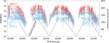
Figure 14. L1 and L2 SNR for all visible GPS satellites.
In the case of GLONASS, both the G1 and G2 codes are known and can be decoded separately, as indicated by different patterns between G1 and G2 SNR (Figure 15). The wavy pattern on the G2 frequency belongs to the lowest GLONASS satellite (R09, elevation 24 to 10°).

Figure 15. G1 and G2 SNR for GLONASS satellites.
This can be further demonstrated by plotting the correlation between the two frequencies of GPS and GLONASS. To make sure that we only visualised the jamming effect, we limited our analysis to satellites with an elevation above 20°. Figure 16 shows the correlation, with the black line indicating a perfect 1:1 correlation. The blue line visualises the linear fit of each satellite's data.

Figure 16. Correlation between L1 and L2 for selected satellites.
These results show the difference between GPS and GLONASS, with a visibly stronger correlation between the GPS frequencies. The GLONASS results demonstrate big separations between G1 and G2, indicating a sudden drop of SNR when close to the jammer.
Currently, the GPS constellation is undergoing modernisation, which includes an additional frequency (L5) and a civilian (open) code on the L2 frequency. Only a limited number of satellites offer this signal now (block IIR-M or younger) and one of them (PRN 25) was visible during the trial. Figure 17 shows the SNR from all frequencies (L1, L2, L5), demonstrating the difference between the L2 and L5 SNR patterns, in all but the duration of the signal gaps. As discussed in Section 5, GLONASS demonstrated later loss of acquisition and an earlier reacquisition.

Figure 17. Comparison between L1, L2 and L5 SNR for GPS SV 25.
These results suggest that a multi-frequency GNSS receiver offers additional protection against jamming, as long as its front end is not saturated. Ongoing upgrade to GPS (L2C and L5) is likely to produce improvement here as well.
6. SUMMARY AND CONCLUSION
Differential GPS (DGPS) is critical for close to shore navigation in the northern North Sea. This paper has demonstrated that the maritime GPS receivers currently in use are affected even by low power jammers, widely available on the market. Results have shown a detectable jamming effect when 1600 metres away from a jammer and a visible effect on positional accuracy 500–1000 metres away. Observed outages of up to 10 metres (Figures 5, 11 and 12) are very hazardous, considering the narrow nature of the Norwegian straits, which are frequently affected by weather and poor visibility. The modern receiver tested demonstrated stronger resilience, with position reported erroneously (on the few metres level) only briefly before losing the position very close to the jammer (50–100 metres). As the trial was limited to only two receivers, it is not possible to generalise these values, and they should only be considered as an approximation. More in-depth testing is required to better understand these results.
Throughout the experiment, the GLONASS G1 frequency remained more resistant to jamming than GPS L1, though it was more affected by intermittent jamming. This could be due to the narrower front-end pass band of the GLONASS receiver (Vladislav et al., Reference Vladislav, Y., Yasyukevich, Jin and Jin2013). A combination of both systems demonstrated better positional accuracy and jamming resilience. This has been traced back, not only to the increased number of satellites used, but also to the higher elevation and better coverage of the GLONASS satellites (Figure 13). Combining both systems is definitely advantageous.
The use of dual frequencies showed a very small increase in GPS accuracy while GLONASS visibly benefited. This has been traced to a correlation between the GPS L1 and L2 frequencies. In all cases, the loss of all signals was correlated with loss of the last GPS satellite. This is different from the front end saturation observed by Bauernfeind et al. (Reference Bauernfeind, Kraus, Dötterböck and Eisfeller2011) as no sudden drop in SNR was present for the GLONASS G2 and GPS L5 frequencies. This might indicate the receiver's hardware overdependence on the GPS signal, but further tests are required for proof of this.
Based on these results, in the case of the updating of maritime receivers, the authors suggest considering an upgrade to a GPS + GLONASS receiver instead of a dual frequency GPS receiver. Should further upgrade be possible, it is worth considering a dual frequency GLONASS update over a GPS one. In this instance it is also possible to detect jamming by comparing G1 and G2 SNR.
The GPS constellation is currently undergoing modernisation, which includes an additional civilian frequency (L5) and an open L2C code on an L2 frequency. Currently, only a limited number of satellites offer these signals (block IIR-M or younger). Data observed during this experiment suggests that use of this modernised signal will offer advantages similar to multi-frequency GLONASS. Further tests are suggested.
ACKNOWLEDGEMENT
The Authors wish to thank the Norwegian Coast Guard for their assistance in conducting of the research. The research was sponsored by The Royal Norwegian Naval Academy. The authors would like to thank Dr Jihye Park, as well as reviewers, for their invaluable comments.


