


Introduction
Bamboo is one of the most efficient structures in nature, combining interesting mechanical properties with an overall low density, at multiple scales [Reference Niklas1, Reference Gibson, Ashby and Harley2]. Figure 1 presents the plant’s main macrostructural and microstructural features. Macroscopically, the plant’s cylindrical stem is divided into regions of hollow internodes and solid nodes [Reference McClure3, Reference Liese4] [Fig. 1(a)]. The vascular bundles in the stem appear broadly spaced and scattered throughout the fundamental tissue of the stem, following the monocotyledon arrangement, namely atactostele [Reference Fahn5]. In the internodes, such arrangement in longitudinal vascular elements is observed by their distribution in a radial density gradient, increasing from the inner to the outer side of the plant [Fig. 1(b)], and then contributing to the culm stiffness [Reference Rich6, Reference Wegst7, Reference Li and Shen8]. On the other hand, the vascular elements also move transversally in the nodes, leading to solid sections (diaphragm) in the stem that prevent its structural failure by ovalization during bending [Reference Zhao, Chen, Ma and Yang9, Reference Wegst and Ashby10, Reference Schulgasser and Witztum11]. Microscopically, the combination of different tissues with complementary properties supports the analogy of bamboo as a natural composite [Reference Amada, Munekata, Nagase, Ichikawa, Kirigai and Zhifei12, Reference Lakkad and Patel13, Reference Low, Che and Latella14]. Vascular elements are encompassed and protected by sclerenchyma bundles, a tissue composed of lignified fibers cells, with thickened secondary cell walls, and surrounded by the parenchyma ground tissue, consisting of living cells with different shapes and physiological functions [Fig. 1(c)]. Although the denser and consequently stiffer sclerenchyma provides structural reinforcement, the parenchyma has been shown to behave like a foam and to distribute local stresses to the whole structure as a matrix [Reference Dixon, Muth, Xiao, Skylar-Scott, Lewis and Gibson15, Reference Palombini, Kindlein, de Oliveira and de Araujo Mariath16]. Despite recent efforts to characterize and study the mechanical behavior of internodal bamboo in the light of its microstructure [Reference Ghysels, Samaey, Tijskens, Van Liedekerke, Ramon and Roose17, Reference Burgert18, Reference Fu, Zhao, Han and Zhou19], the nodal region represents a far more complex arrangement of vascular bundles because of their need for rearrangement, especially in new vegetative and reproductive branches, thus requiring high-resolution and noninvasive characterization approaches.
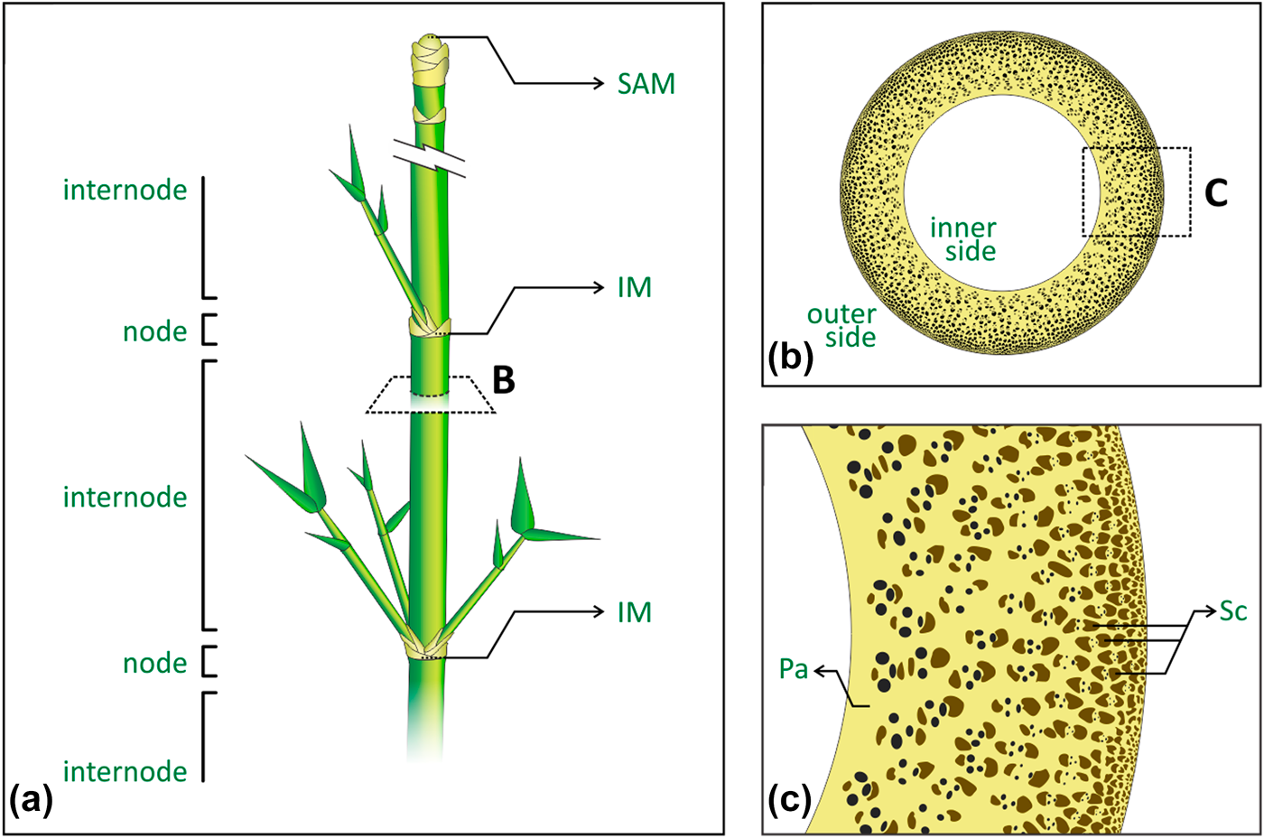
Figure 1: Bamboo main macrostructural and microstructural features: (a) stem segmentation of regions of nodes and internodes, where SAM is the shoot apical meristem, and IM is the intercalary meristem; (b) internode cross-section showing the atactostele gradient distribution of the vascular bundles, from the inner to the outer side of the stem; (c) tissues encompassing the vascular elements, where Pa is the parenchyma and Sc is the sclerenchyma bundles.
The constitutive properties of bamboo parenchyma and sclerenchyma can be estimated based on numerical models for the three-dimensional properties of porous materials [Reference Colombo, Dunand and Kumar20], or cellular solids, following the pioneer studies of Gibson and Ashby [Reference Gibson and Ashby21], such as foams and honeycombs. Principally, such properties are related to the (i) shape and (ii) distribution of cells or pores, the (iii) thickness of their cell walls or edges, as well as the (iv) properties of the solid cell material [Reference Gibson, Ashby and Harley2, Reference Gibson and Ashby22]. Recently, such models were also used as a base to study the mechanical properties of several materials, such alumina [Reference Seeber, Gonzenbach and Gauckler23], titanium [Reference Wen, Yamada, Shimojima, Chino, Hosokawa and Mabuchi24], silica [Reference Toivola, Stein and Cook25] and cellulose acetate [Reference Zepnik, Hendriks, Kabasci and Radusch26] foams, and trabecular bone [Reference Keaveny, Morgan, Niebur and Yeh27]. Moreover, those models were also used as a base for different approaches [Reference Boettge, Standke, Fuessel and Adler28], such as the ones presented by Richardson et al. [Reference Richardson, Peng and Remue29] and Buciuman et al. [Reference Buciuman and Kraushaar-Czarnetzki30], mostly used for foam-like materials. The parenchyma can be morphologically characterized as a honeycomb because of its prismatic cellular configuration [Reference Gibson, Ashby and Harley2]. However, its mechanical behavior resembles that of a closed-cell foam with curved cell walls [Reference Palombini, Kindlein, de Oliveira and de Araujo Mariath16, Reference Dixon and Gibson31]; therefore, the calculation of their mechanical properties has been assessed from 3D numerical models of such materials [Reference Dixon, Muth, Xiao, Skylar-Scott, Lewis and Gibson15].
Characterizing the structural behavior of efficient plants like bamboo is essential for understanding its performance to apply such information in the development of improved bioinspired projects [Reference Song, Xu, Wang, Wu and Zou32, Reference Hu, Song, Dang and Zhang33, Reference Kindlein Júnior and Guanabara34]. Particularly, the inclusion of solid sections, similar to nodes, in hollow structures, representing a simplified version of bamboo’s diaphragm, has been shown to be a key part of the overall performance. For instance, Zou et al. [Reference Zou, Xu, Wei, Wang and Liu35] verified in a bamboo bioinspired structure that the nodes acted as joints and contributed to better energy-absorbing capabilities. Similarly, Zhao et al. [Reference Zhao, Chen, Ma and Yang9] and Liu et al. [Reference Liu, Tong, Tang, Liu and Zhang36] also demonstrated that node-like features can increase the performance of bionic or biomimetic structures. However, even with improvements observed in simplified versions of the diaphragm, the plant’s actual nodal region has not been fully investigated either anatomically or biomechanically, i.e., by also considering the complex arrangement of vascular bundles in its structure, thereafter leading to divergences in the literature. Shao and Wang [Reference Shao and Wang37] showed that the nodes do reinforce bamboo culms at multiple loads, with the exception of longitudinal tension. In addition, Schulgasser and Witztum [Reference Schulgasser and Witztum11] found that the nodal region also prevents longitudinal crack propagations. On the other hand, Taylor et al. [Reference Taylor, Kinane, Sweeney, Sweetnam, O’Reilly and Duan38] affirmed that nodes would have to be closely spaced for a significant effect on the mechanical performance of the culm. Authors also suggested that nodes have evolved to avoid failure near the branch. Anatomically, Shao and Wang [Reference Shao and Wang37] affirmed that one part of the vascular bundles bends inward and outward, and then spreads along the original direction, whereas the other bundles spreads transversely. Liese and Tang [Reference Liese, Tang, Liese and Köhl39] state that some vascular elements pass directly through the node, while connecting with others from the diaphragm. Then again, Taylor et al. [Reference Taylor, Kinane, Sweeney, Sweetnam, O’Reilly and Duan38] stated that once acting as branch points, the sclerenchyma bundles are forced to deviate from the longitudinal orientation in the nodes.
The complex arrangement of vascular bundles in the nodal region is a key topic for characterizing the morphostructural characteristics of bamboo, either for a better understanding of the material’s behavior or for application in bioinspired projects. However, its 3D morphological reconstruction and mechanical role regarding its anatomy remain unexplored. Ding and Liese [Reference Ding, Liese, Soc and Chapman40] presented a primary illustration of the structure of a bamboo node with emphasis on bridges and vascular anastomoses, based on physical serial sections of a sample. Another approach was conducted by Haushahn et al. [Reference Haushahn, Speck and Masselter41], in which the nodal vascular bundles of a Dracaena reflexa sample (an arborescent monocotyledon) was segmented by aligning and digitalizing transversal serial sections, revealing the vascular arrangement of the nodal region in a 3D visualization. Both methods required physical sectioning of the samples, a destructive procedure that could damage delicate tissues. Therefore, noninvasive techniques have also been used, such as X-ray computed tomography (CT). Huang et al. [Reference Huang, Chang, Ansell, Chew and Shea42] used CT to present longitudinal and transversal sections of the node of a Moso bamboo (Phyllostachys edulis) sample, still no 3D visualization of the µCT stack was performed. Peng et al. [Reference Peng, Jiang, Liu, Fei, Yang, Qin, Ren, Yu and Xie43] used X-ray microtomography (µCT) in a bamboo sample (Pleioblastus gozadakensis) revealing a partial 3D view of the node, yet authors did not perform a segmentation procedure, thus impairing the actual visualization and the correct interpretation of the morphology of the vascular bundles.
In addition to a better visual analysis of a region of interest (ROI) of plants [Reference Brodersen and Roddy44, Reference Nogueira, Kuhn, Palombini, Rua, Andrello, Appoloni and Mariath45], segmentation of µCT stack images allows such models to be exported to 3D file extensions, e.g., for application in 3D printing [Reference Dixon, Muth, Xiao, Skylar-Scott, Lewis and Gibson15, Reference Palombini, Kindlein Júnior, Silva and de Araujo Mariath46, Reference Rengier, Mehndiratta, von Tengg-Kobligk, Zechmann, Unterhinninghofen, Kauczor and Giesel47] and finite element analysis (FEA) [Reference Palombini, Kindlein, de Oliveira and de Araujo Mariath16, Reference Maire, Fazekas, Salvo, Dendievel, Youssef, Cloetens and Letang48]. Notably, Petit et al. [Reference Petit, Meille and Maire49] present a broad review and highlight the main applications of µCT and FEA for the study of cellular solids. In another review of FEA of natural fibers and composites reinforced with natural fibers, Xiong et al. [Reference Xiong, Shen, Hua, Liu, Li, Wan and Miao50] highlight the importance of considering the irregular cross-section of fibers to improve the accuracy of the analysis. Authors also comment on the benefits of importing the actual geometry directly from µCT as an approach to characterize the sample’s microstructure. A µCT-based FEA of the internode region of bamboo was also conducted [Reference Palombini, Kindlein, de Oliveira and de Araujo Mariath16] by considering the actual sclerenchyma distribution into the parenchyma under a compressive load. Results were comparable to those of experimental tests, although the nodal region was not represented. Silva et al. [Reference Silva, Walters and Paulino51] modeled a two-node long bamboo stem for FEA and compared the constitutive properties of homogenized isotropic, orthotropic, and functionally graded material (FGM), which represents the atactostele distribution of vascular bundles. Authors verified that despite the higher computational effort, the model with FGM constitutive properties is needed for a more accurate estimate of stresses on the model. However, once the FGM was applied in the internode regions only, the vascular bundles of the diaphragm regions of the nodes were neglected. Consequently, those regions were analyzed with minimum mechanical properties and resulted in much smaller local stresses. Therefore, advances in high-resolution imaging methods linked to FEA in complex microstructural arrangements are essential to provide better insights not only into natural materials but also for the composite industry [Reference Xiong, Shen, Hua, Liu, Li, Wan and Miao50, Reference Naouar, Vidal-Salle, Schneider, Maire and Boisse52].
This study presents the 3D characterization of the morphology and the structural analysis of a 4-axes nodal bamboo sample, regarding its anatomy in that region. High-resolution µCT was used to image the sample, which was then segmented according to the complex arrangement of the vascular bundles. The 3D model was characterized, including the assessment of the volume, porosity, relative density, and distribution of the plant’s tissues and vascular bundles [Reference Palombini, Kindlein, de Oliveira and de Araujo Mariath16]. Relative density data from the parenchyma and the sclerenchyma were used to determine the constitutive properties of both tissues. Finally, a nonlinear FEA was performed using the actual distribution of the vascular bundles in the diaphragm to investigate the behavior of the nodal region under a compressive load.
Results and discussion
Morphological analysis
The 3D reconstruction of the bamboo nodal region with the secondary branches is presented in Fig. 2. Figures 2(a)–2(g), present the development of the branches into secondary axes, with the combination of binary masks of segmented vascular bundles and µCT slices distributed from the bottom up of the model. In the lower part of the diaphragm [Fig. 2(a)], the marginal vascular bundles leave the central cylinder, vascularizing the leaves sheaths; at the same time, other marginal bundles migrate out of the central cylinder, with the addition of marginal bundles from the region opposite from it, passing through the main bundles to the outside [Figs. 2(b)–2(d)].

Figure 2: µCT 3D reconstruction of the nodal region of bamboo with secondary branches. Details a–g present µCT slices (from the bottom up of the sample) showing the development of leaves sheaths and stem branches, highlighting the anastomosis of vascular bundles while connecting the main axis (green) to the secondary axes (purple, yellow, and red). Scale bars = 1 mm.
As the reference µCT slice position approaches the top region of the diaphragm, vascular bundles of secondary axes are shown surrounding and enclosing the ones of the primary axis, while moving transversally [Fig. 2(c)], and start to align with their respective secondary branches [Fig. 2(d)], until found separated into branches [Fig. 2(e)]. It is noteworthy that most secondary bundles kept their transversal relative position in the secondary axis regarding the original scattered distribution of the primary one (atactostele). In addition, after distinctively separated into new axes in the upper part of the node [Fig. 2(f)], the vascular bundles of the primary axis exhibit a considerable thickening, by increasing in their transversal dimension, particularly in the axillary region of the main axis [Fig. 2(g)]. Such behavior is in accordance with the description of bamboo nodal structure reported by Liese and Tang [Reference Liese, Tang, Liese and Köhl39] and Shao and Wang [Reference Shao and Wang37]. The development and horizontal movement of the vascular bundles can also be visualized in supplementary video (SV1) of µCT slices.
Figure 3 presents the 3D reconstruction of the vascular bundles segmented based on the µCT imaging. By hiding the bundles of the primary axis [Fig. 3(a)—green], the ones of the secondary axes (purple, yellow, and red) can be seen interweaving with them. Horizontal movement of the secondary bundles can be better observed in Fig. 3(b). While developing vertically through new branches, the bundles also move to the opposite direction of their respective axis before splitting into a new branching. Those characteristics can also be observed in Fig. 3(c), with the empty space regarding the hidden vascular bundles of the primary axis. Despite not presenting the sclerenchyma thickening above the nodal region, the interlocking of the secondary bundles also suggests a reinforced connection with the main axis. An interesting feature observed is the continuity of the secondary branches from the basal portion until the branching, without bridges, or vascular traces, connecting the secondary axes with the main axis. Such structures develop in the internode, below the nodal region [Reference Palombini, Kindlein, de Oliveira and de Araujo Mariath16].

Figure 3: 3D reconstruction of vascular bundles from µCT of the nodal bamboo region with secondary branching: (a) vascular bundles of the main axis interweaving with the ones of the secondary axes; (b) vascular bundles of the secondary axes only; (c) details of the transversal movement of secondary vascular bundles. Scale bars = 1 mm.
Total volume, relative density, and porosity of the segmented regions of sclerenchyma and parenchyma were quantified. The relationship of those values with each µCT transversal slice position is presented in Fig. 4. Parenchyma presented an absolute volume of approximately 57.4 mm3, with an average relative density of 0.317, and, consequently, a porosity of 68.3%. Sclerenchyma resulted in an absolute volume of around 28.4 mm3, which can be divided into the main axis, 15.4 mm3, and the three secondary axes, or 2.2 mm3, 7.5 mm3, and 3.3 mm3. The tissue also presented a relative density of approximately 0.860, giving a porosity of approximately 14%. Values were generally similar to those reported in the literature [Reference Amada, Munekata, Nagase, Ichikawa, Kirigai and Zhifei12, Reference Palombini, Kindlein, de Oliveira and de Araujo Mariath16, Reference Janssen53]. The sample consisted of approximately 415 vascular bundles distributed in the main and secondary axes. Individually, the bundles presented an average volume of approximately 0.102 (±0.013) mm3, average cross-section area of 0.011 (±0.002) mm2, and average thickness of 155.514 (±14.861) µm, approximately, calculated by the Analyze Particles tool and the 3D Objects Counter plugin [Reference Bolte and Cordelières54].

Figure 4: Relative volume (%) and relative density (ρ*/ρS) of parenchyma and sclerenchyma related to each transversal slice position of the µCT-segmented nodal bamboo. Dotted and dashed lines represent the average values of ρ*/ρS for the parenchyma and sclerenchyma, respectively.
Overall, the relative density of the parenchyma and sclerenchyma follows a similar pattern from the bottom to the top of the sample. In addition, by relating the relative density data of Fig. 4 with the sequential slices of Fig. 2, some density characteristics of bamboo tissues can be listed. The slight decrease of the (ρ*/ρS) after 1 mm, in the lower part of the node, regards the start of scattering of secondary bundles into new axes, seen in Figs. 2(a) and 2(b). Relative density then increases for both tissues until the slice position reaches approximately 5 mm, in the upper part of the node, corresponding to Figs. 2(d) and 2(e). Such behavior indicates that by developing new vascular bundles, bamboo sclerenchyma cells tend to thicken or get more lignified. At the 7 mm slice position, after a physical detachment of the main axis into three secondary branches [Fig. 2(f)], an increase of the cell lumina is noticed, reducing the relative density. Finally, in the region right above the nodal region [Fig. 2(g)], the sclerenchyma thickening of the main axis resulted in a larger relative volume and a greater relative density, before the slice position of 8 mm. This may suggest a stiffness increase in that bamboo region. The last decrease of (ρ*/ρS) after that is related to the end of the sample positioning in the µCT field of view. Regarding the vascular bundles, calculated by the Analyze Particles tool, their average cross-section area and thickness decrease roughly 25% with the relative increase of the sclerenchyma, and they increase while the sclerenchyma bundles are slenderer. As expected [Reference Fahn5, Reference Raven, Evert and Eichhorn55], such behavior indicates that a sclerenchyma thickening induces a constriction in the vascular elements in key points, where the secondary axes are physically divided from the primary one.
Finite element analysis
The discretizing process of the 3D segmented model of the nodal region of bamboo focused on the shape of the vascular bundles, mostly represented by the sclerenchyma. The ground volume, corresponding to the parenchyma, involved the sclerenchyma, following the main and secondary axes. Because of the proceeding of a nonlinear FEA, where the maximum compressive load is assessed, leaves’ sheaths and other external fine structures were suppressed from the 3D model during segmentation, to avoid excessively local stresses that could underestimate the overall result, in addition to increasing the total number of elements in the mesh. Figure 5 shows the result of the discretizing process of the nodal bamboo. The assembly model [Fig. 5(a)] was divided into the parenchyma and sclerenchyma parts, shown in white and green respectively. Figure 5(b) presents the sclerenchyma elements only, by hiding the parenchyma part.

Figure 5: Meshing process for the FEA of the µCT-based nodal region of bamboo: (a) discretized assembly model with the regions of parenchyma (white) and sclerenchyma (green); (b) sclerenchyma region only, by hiding the parenchyma mesh elements; (c) detail of the tetrahedral mesh of the assembly. Mesh elements contours were hidden in A and B to improve the visualization of the 3D model.
The entire assembly model consisted of a single tetrahedral mesh (type C3D4) with approximately 22 million elements and about 3.6 million nodes [Fig. 5(c)]. Two materials and sections were defined based on the elements of the sclerenchyma and the parenchyma, being set to the mesh. A fine mesh with a uniform element size was required because of the geometry of sclerenchyma bundles. To avoid an even more refined mesh, vascular elements of phloem and xylem were suppressed. Such details would require a considerably greater number of mesh elements and, consequently, more computational resources on solving the analysis.
Using Eqs. (1)–(4), the constitutive properties for the parenchyma and sclerenchyma tissues were defined based on their respective relative density data. Elastic modulus resulted in approximately 4.0 GPa for the parenchyma and 34.2 GPa for the sclerenchyma, as well as the values of 25.3 MPa and 213.3 MPa for their compressive strength, respectively. Once the orientation of the sclerenchyma bundles into the geometry was defined by the mesh elements distribution, the tissue was already presented in a slender, fiber-like configuration. Therefore, both materials were set as isotropic using the above materials properties.
The initial total force pressure loading of 100 MPa applied in the model showed a maximum load increment of 0.6207, and for bigger values, there was no convergence in the FEA. Next, a second analysis was performed, adjusting the loading to the maximum increment value reported. The model then converged to a maximum axial compressive strength of approximately 62 MPa. The result is in the same range of those in the literature for physical tests of Bambusa tuldoides. For instance, Colli et al. [Reference Colli, do Nascimento, Xavier, Rubim, Colli, do Nascimento, Xavier and Rubim56] found compressive strength values ranging from 46 MPa to about 72 MPa for samples located at nodal regions, from the base to the top portion of the culm. Nascimento et al. [Reference Nascimento, Stachera and Xavier57] found compressive values from 65.8 to 88.2 MPa. Conversely, But and Chia [Reference But, Chia, Dransfield and Widjaja58] data report compressive values of around 30 MPa in the nodal region, and Janssen [Reference Janssen59] found values ranging from 27 to 43 MPa. However, such variation is not surprising and can somewhat be expected because of the natural variability of bamboo, as well as the several controlled factors, such as the sample maturity and position in the culm, collecting and drying protocols, among others [Reference Niklas1, Reference Liese4, Reference Palombini, Kindlein, de Oliveira and de Araujo Mariath16]. Therefore, in µCT-based FEA of plants, qualitative results of the analysis can be considered important as well, in terms of investigating the complex mechanical behavior of the sample.
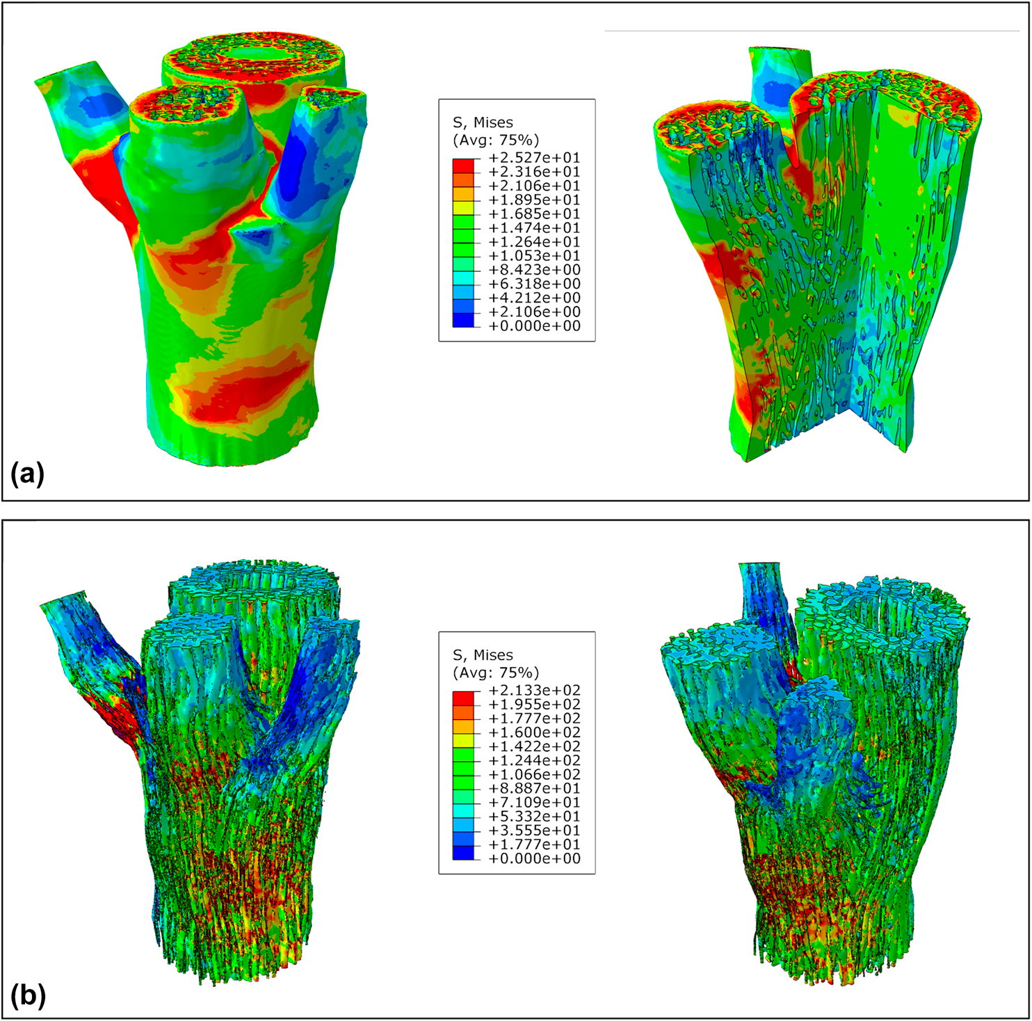
The von Mises stress results at the compressive failure of the converged FEA are presented in Fig. 6. Because of differences in range values of the von Mises stresses legends from the parenchyma and sclerenchyma sets (automatically recalculated based on their respective limiting values of σP and σSc) as well as for a better visualization, tissues were presented separately. The parenchyma model and its internal view cut are shown in Fig. 6(a). Higher stressed zones were mostly noticed in lower branching regions of secondary axes, in addition to the upper face of the assembly, where the compressive load was applied. Secondary axes were also more stressed in the connecting regions among other branches. Despite having a considerable amount of sclerenchyma bundles, though, the inner zone of the bottom part of the sample presented lower stress levels.

Figure 6: The von Mises stress results at the compressive failure of the µCT-based FEA of the nodal region of bamboo: (a) parenchyma elements set only, and internal view cut; (b) sclerenchyma elements set only. Mesh elements contours were hidden to improve the visualization of the colored regions.
Although activating several sclerenchyma reinforcement bundles in all axes [Fig. 6(b)], the parenchyma presented less stressed regions in the primary one. Besides dissipating the compressive stress among the entire sample, and then mechanically acting as a foamy matrix in a composite analogy [Reference Dixon, Muth, Xiao, Skylar-Scott, Lewis and Gibson15, Reference Palombini, Kindlein, de Oliveira and de Araujo Mariath16], such behavior indicates a tendency for the parenchyma to preserve its primary axis. Even with a uniform distribution of the compressive pressure, with most stressed regions concentrated in secondary axes, it can be inferred that the plant would tend to protect their main axis with their intercalary meristem (IM), an embryonic tissue founded between mature tissues, in bamboo at the base of the internode; and the shoot apical meristem (SAM), the terminal part of the shoot immediately above the uppermost leaf primordium [Fig. 1(a)]. Although each branch also has an IM and a SAM, in the main axis, these meristems hold a dominant control answering for the plant architecture [Reference Kerstetter60]. Moreover, the thickening of sclerenchyma bundles in the top portion of the primary axis, observed in the µCT and relative density analyses, shows that this region was older than the branching portion and then received additional secondary cell wall deposition. In addition, the dominant control of the main axis presents an effort for the plant to increase the strength in that region; with larger bundle transversal areas, von Mises stress distribution tends to be relatively smaller [Reference Mortensen61, Reference Boyd62], as seen in the results.
Our findings regarding the mechanical role of the nodes in bamboo support those of Shao and Wang [Reference Shao and Wang37] and Zou et al. [Reference Zou, Xu, Wei, Wang and Liu35], once such regions improve the dissipation of stresses and reinforce the overall culm at compressive loads. Similar to the conclusions of Taylor et al. [Reference Taylor, Kinane, Sweeney, Sweetnam, O’Reilly and Duan38], related to the evolution of bamboo nodes to prevent failure in the vicinity of the branch, our results suggest that the plant tends to preserve the primary axis at compressive loads, leading greater stresses to be transferred to the secondary branches. Anatomically, such behavior would allow the development of lateral structures, such as branches and leaves, without compromising the strength of the primary axis [Reference Fahn5]. Also, the longitudinal and transversal spreads of vascular bundles in the node, in addition to the sclerenchyma thickening, were also in accordance with the literature [Reference Shao and Wang37, Reference Liese, Tang, Liese and Köhl39], but not their origin, as demonstrated here in 3D model for the first time. On the other hand, it is noteworthy that some characteristics reported in the literature, regarding the 3D arrangement of vascular bundles in the nodal region of bamboo, were not observed in our µCT reconstruction. Particularly, the presence of vascular bridges and branching anastomosis at the diaphragm [Reference Ding, Liese, Soc and Chapman40] were observed to actually develop below the nodal zone [Reference Palombini, Kindlein, de Oliveira and de Araujo Mariath16]. Then, again, such configuration may also represent a way for the plant to protect important developing tissues [Reference McClure3]. Finally, the fiber bundles interweaved configuration could be also explored in bamboo-inspired bionic designs [Reference Zhao, Chen, Ma and Yang9, Reference Liu, Tong, Tang, Liu and Zhang36] to induce the stress distribution into regions of interest and by preventing particular regions from overstressing.
Conclusions
The branching morphology and the mechanical behavior of the nodal region of bamboo were assessed using high-resolution µCT and a nonlinear FEA using the 3D reconstructed model. We propose a relationship of the complex bamboo anatomy with its structural behavior under the maximum compressive load. The main contribution of the research is to present one of the first 3D microstructural reconstructions of the complex nodal vascular system of monocots, by means of identifying its arrangement within the node and tracking the lateral movements of the bundles, in addition to evaluating its role in distributing uniform axial stresses in the stem. Data from the µCT characterization were used to estimate the constitutive properties of each tissue and also to assist in the interpretation of the FEA model.
Bamboo vascular elements in the nodal region were characterized as a complex arrangement of bundles that connect and interweave the primary axis to those of the secondary ones. By originating below the basal node, marginal secondary vascular trace bundles can be considered a way for the plant to develop lateral branches whereas protecting the main axis from mechanical stresses. The increase of sclerenchyma relative volume in the stem after branching, in addition to the thickening of fiber bundles, was observed in the µCT imaging and reconstruction. Such characteristics were related to a reinforcement above the node to increase the local strength of the plant. Although moving from the marginal traces, transversally and across the primary vascular elements, the secondary bundles tend to preserve their relative final position in the branch similar to their original location when in the primary axis. µCT reconstruction also allowed to visualize the real development of the bundles and then to compare to features described in the literature, based on more traditional sequential cutting techniques.
µCT-based FEA showed to be an important way to analyze the qualitative aspects of the microstructure of plants. Results of the nonlinear FEA presented a maximum value for the axial compressive strength in agreement to physical tests reported in the literature for B. tuldoides. However, as seen in the broad range in the referred data, several variables may influence the strength of a bamboo sample. Therefore, the µCT-based FEA approach can be better used as a tool for assessing the microstructural performance of the sample. Our findings reinforce the known foam-like matrix behavior of the parenchyma, by distributing stresses and mechanically activating the reinforcement sclerenchyma bundles along the stem. Higher stressed regions were mostly found in the secondary axes during compression, specifically in their lower regions and in the interconnecting zones among other branches. Over the maximum compressive load, bamboo was assessed as having the tendency to transfer stresses to the lateral branches to preserve the lower and central regions of the main axis, given that those regions include important development tissues for the plant, as the intercalary meristem and the SAM. The characterized bundles configuration may also be studied for the design of innovative biomimetic designs, by inducing local regions of a jointed structure to be preserved over a global mechanical failure. Particularly, with such a bioinspired reinforcement network, a structure could be designed to collapse at specific zones, when overloaded. The selective load-bearing capabilities of bamboo can also be used to assist the prediction of a safely global failure mode of a structure, meanwhile preserving local spots.
Materials and methods
Sample preparation
A sample of B. tuldoides Munro was collected from the state of Rio Grande do Sul in Southern Brazil. B. tuldoides is native to southern China and Vietnam, having been introduced and cultivated in Central and South America [Reference Ohrnberger63]. The species reaches approximately up to 10–12 m in height, and its stem reaches 3–5 cm in diameter [Reference Palombini, Kindlein, de Oliveira and de Araujo Mariath16]. The chosen ROI was the apical stem of a mature plant (Fig. 7), with lignified sclerenchyma cell walls, because of the development of secondary axes in the nodal region [Fig. 7(a)] and consequently the presence of vascular anastomosis. Naturally, once the sample was collected from the top portion of the stem, it consisted of a relatively small specimen [Fig. 7(b)]. A smaller sample facilitates µCT image acquisition and leads to better resolution.

Figure 7: Sample preparation of bamboo (B. tuldoides) for X-ray microtomography: (a) top portion of the stem; (b) nodal region of the apical stem of the specimen, consisted of a primary axis generating lateral sheaths and buds; (c) cross-sectioning of the sample; (d) sectioned sample; (e) µCT projection.
The sample was manually sectioned transversally above the nodal region, with a scalpel [Fig. 7(c)]. Because of its apical position in the stem, sclerenchyma cell walls presented a less lignified level; therefore, no softening protocol was necessary for an even sectioning. The sample was then fixed in FAA50 (adapted from [Reference Johansen64]), composed of five parts of formalin, five parts of acetic acid, and 90 parts of 50% ethanol (v/v) [Reference Sampaio, de Chiara Moço and Mariath65] and kept soaked for 7 days. After rinsing in water, the sample was immersed in 50% ethanol for 1 h and passed to 70% ethanol for a further 1 h. It was then immersed in 2,2-dimethoxypropane for 24 h as an intermediary method in the drying process [Reference Palombini, Kindlein, de Oliveira and de Araujo Mariath16]. Finally, it was kept in a dehumidifying cabinet for 2 days to finish drying.
X-ray microtomography (µCT)
X-ray microtomography (µCT) is a noninvasive, high-resolution method to acquire a 3D imaging of a sample based on the attenuation of the radiation, allowing further analyses [Reference Landis and Keane66]. 3D imaging acquisition was conducted in a Zeiss Xradia 510 Versa CT (Zeiss X-ray Microscopy, Pleasanton, California). Because of the overall small size of the bamboo sample [Fig. 7(d)], it was possible to place it entirely within the field of view of the equipment. Fitting the sample in the field of view reduces artifacts, leading to optimal results in the analysis [Reference Cidade, Palombini, da Cunha Duarte and Paciornik67, Reference Stock68]. The 510 Versa has a sealed transmission source that reaches 160 kV and 10 W, combining geometric and optical magnification. Therefore, it was possible to zoom in to adjust the field of view to the ROI. Using an objective lens of 4×, the bamboo sample was scanned with an X-ray source voltage and current of 80 kV and 88 μA, for a voxel size of 5.611 μm after binning (source-sample distance = 40 mm, sample-detector distance = 8 mm). LE1 X-ray filtering was used to reduce beam hardening. Two acquisition sets (upper and lower parts) were performed to scan the sample. A total of 1601 projections [Fig. 7(e)] in 0.225° steps were obtained with 1 s exposure time for each set, resulting in a total acquisition time of 2 h 15 min.
Image slices were combined and reconstructed from the projections with a noniterative filtered backprojection algorithm in the software provided by the manufacturer and exported as a stack of DICOM images. Images were processed and analyzed with the open-source Fiji software, a distribution of ImageJ [Reference Schindelin, Arganda-Carreras, Frise, Kaynig, Longair, Pietzsch, Preibisch, Rueden, Saalfeld, Schmid, Tinevez, White, Hartenstein, Eliceiri, Tomancak and Cardona69], and processing steps are shown in Fig. 8. The original DICOM stack [Fig. 8(a)] was first enhanced with the non-local means [Reference Buades, Coll and Morel70] noise reduction filter [Fig. 8(b)], an edge-preserving low-pass filter. Figures 8(a1) and 8(b1) demonstrate details of the same slice region before and after noise reduction processing, respectively.

Figure 8: X-ray microtomography image stack processing on nodal bamboo sample: (a) original slice and detail (a1) of the noise in a region; (b) image filtered with non-local means denoising filter and detail (b1) of the same region after noise reduction; (c) manually segmented sclerenchyma of vascular bundles from primary axis (green) and secondary axes (purple, yellow, and red); (d) binary masks of segmented bundles.
For a better visualization in addition to an accurate analysis of bamboo vascular bundles in the nodal region, the sclerenchyma bundles were segmented manually and individually [Fig. 8(c)]. Once bamboo bundles tend to bend and shift transversally, tracking and identifying their origin and displacement is rather difficult. Therefore, each axis was also segmented independently, being divided into the primary axis and the three secondary axes. The segmentation editor plugin [Reference Schindelin, Arganda-Carreras, Frise, Kaynig, Longair, Pietzsch, Preibisch, Rueden, Saalfeld, Schmid, Tinevez, White, Hartenstein, Eliceiri, Tomancak and Cardona69] was used in the process, also generating binary masks that could be exported and analyzed. Cell lumina regions of the conducting elements of xylem and phloem were preserved, by subtracting an additional lumina mask from the segmented binary masks, using the Image Calculator operation in Fiji. The vascular bundles were also quantified in terms of total number, average volume, cross section area, and thickness, using Analyze Particles tool and the 3D Objects Counter plugin for Fiji [Reference Bolte and Cordelières54]. Finally, the resulting binary masks [Fig. 8(d)] were exported into binary STL files, according to each axis, for further morphological analyses.
Finite element analysis (FEA)
To assess the mechanical behavior of nodal bamboo region, a FEA was performed in the processed µCT stack. The discretization process of STL files into a volume mesh was performed with Gmsh [Reference Geuzaine and Remacle71], a free automatic 3D finite element mesh generator. A single mesh was used to discretize the µCT bamboo sample; however, group elements were attributed to the parenchyma and sclerenchyma regions for independent constitutive properties. To reduce the overall number of elements in the discretized mesh, xylem and phloem lumina void regions were removed from the vascular bundles. Such details would force the mesh size to an even more refined contour, significantly increasing the number of elements and thus requiring more processing power to solve the FEA. The volume mesh was exported to INP model file extension from Abaqus/CAE (Dassault Systèmes Simulia® Corp., Providence, Rhode Island) FEA software.
As cellular solids, modeling the 3D mechanical properties of bamboo tissues considers their relative density (ρ*/ρS)2, and such data can be extracted from the µCT processed images [Reference Palombini, Kindlein, de Oliveira and de Araujo Mariath16]. The value represents the volume fraction of a region or the density of the cellular material (ρ*) divided by that of the solid cell wall material (ρS). Therefore, it can also be related to the porosity or the void fraction of the region (1 − ρ*/ρS)2. Relative density data were assessed for the plant tissues with a binary mask of the stack and calculating the amount of volume for each region with Fiji. The elastic moduli of the parenchyma (E P) and the sclerenchyma (E Sc) were defined by [Reference Palombini, Kindlein, de Oliveira and de Araujo Mariath16]
 $${E_{\rm{P}}} = \left( {{{{\rho ^*}} \over {{\rho _{\rm{S}}}}}} \right)_{\rm{P}}^{\rm{2}}{E_{\rm{s}}}\quad ,$$
 $${E_{{\rm{Sc}}}} = {\left( {{{{\rho ^*}} \over {{\rho _{\rm{S}}}}}} \right)_{{\rm{Sc}}}}{E_{\rm{s}}}\quad ,$$
where E s is the elastic modulus of the solid cell wall material of bamboo, or approximately 39.8 GPa [Reference Palombini, Kindlein, de Oliveira and de Araujo Mariath16, Reference Dixon and Gibson31], and (ρ*/ρS)P and (ρ*/ρS)Sc are the relative density for the parenchyma and the sclerenchyma, respectively. The power relationship of parenchyma’s relative density to its elastic modulus is due to the tissue’s geometric characteristics of a closed cell foam [Reference Gibson, Ashby and Harley2]. Because of the relative slenderness of the sclerenchyma bundles in the whole model, in addition to their irregular orientation along the diaphragm, the tissue was assumed as an isotropic material. Even though fiber cells are known to be an orthotropic material in a greater resolution [Reference Palombini, Kindlein, de Oliveira and de Araujo Mariath16], attributing an orthotropic material to small fiber bundles would require partitioning the sclerenchyma model into multiple regions with unique orientations in Abaqus/CAE, in addition to increasing the computational effort of the analysis.
In this study, a nonlinear FEA was conducted to verify the mechanical behavior of the nodal bamboo sample during a compressive loading. Hence, nonlinear constitutive properties were also added to the model. The compressive strength values for the parenchyma (σP) and the sclerenchyma (σSc) were also dependent on their relative density and can be defined according to
 $${\sigma _{\rm{P}}} = 0.3\left( {{{{\rho ^*}} \over {{\rho _{\rm{S}}}}}} \right)_{\rm{P}}^{{3 / 2}}{\sigma _{{\rm{fs}}}}\quad ,$$
 $${\sigma _{{\rm{Sc}}}} = {\left( {{{{\rho ^*}} \over {{\rho _{\rm{S}}}}}} \right)_{{\rm{Sc}}}}{\sigma _{\rm{s}}}\quad ,$$
where σfs is the modulus of rupture of bamboo solid cell wall material, being defined as 472 MPa, and σs is the axial compressive strength of the solid cell wall material, defined as 248 MPa [Reference Palombini, Kindlein, de Oliveira and de Araujo Mariath16, Reference Dixon and Gibson31]. σfs is used for the parenchyma because of the foam-like characteristic, assuming cell wall bending and failure by plastic hinges under uniaxial stresses [Reference Gibson, Ashby and Harley2, Reference Palombini, Kindlein, de Oliveira and de Araujo Mariath16]. The 0.3 constant in Eq. (3) represents the fitting data results for the foam model during plastic collapse [Reference Gibson, Ashby and Harley2]. Poisson ratio set for the parenchyma and sclerenchyma was 0.4 and 0.22, respectively [Reference Palombini, Kindlein, de Oliveira and de Araujo Mariath16].
An elastoplastic regime was set in the analysis, with the purpose of investigating the stresses and strains in the nodal bamboo model during the maximum compressive load supported. An initial axial compressive load of 100 MPa, defined as total force, was distributed in the top cross-section face of the model. The analysis was executed until converging to a maximum compressive load. The bottom face of the model was constrained as encastre. Finally, a self-contact property (surface-to-surface interaction, frictionless) was set in the model to prevent neighboring regions to intersect during loading.
Acknowledgments
This study was financed in part by the Coordenação de Aperfeiçoamento de Pessoal de Nível Superior—Brasil (CAPES)—Finance Code 001. This research was supported by the National Council for Scientific and Technological Development (CNPq—Brazil), the PROPESQ–UFRGS, and the Research Support Foundation of Rio Grande do Sul (FAPERGS). Authors thank Dr. Marcos Henrique de Pinho Mauricio, from DEQM PUC-Rio, and Dr. Haimon Dinis Lopes Alves, from UERJ, for the µCT image acquisition.


 Open access