


Introduction
Drumlins are widespread geomorphic features that result from subglacial processes acting at the ice/bed interface. Drumlin fields that formed during former glaciations are found over much of the northern hemisphere (Clark and others, Reference Clark, Hughes, Greenwood, Spagnolo and Ng2009). Additionally, actively forming drumlin-like features have been imaged, using geophysical techniques, beneath the Antarctic ice sheet (King and others, Reference King, Woodward and Smith2007; Larter and others, Reference Larter2009). Widespread study of drumlins (see Menzies, Reference Menzies1979, Reference Menzies1984; Clark and others, Reference Clark, Hughes, Greenwood, Spagnolo and Ng2009; Stokes and others, Reference Stokes, Spagnolo and Clark2011; Stokes and others, Reference Stokes, Fowler, Clark, Hindmarsh and Spagnolo2013a, Reference Stokes2013b for a review) has provided an extensive set of observations and have led to a range of drumlin formation models (Boulton, Reference Boulton, Menzies and Rose1987; Shaw, Reference Shaw2002; Schoof, Reference Schoof2007; Clark, Reference Clark2010; Fowler, Reference Fowler2010; Hooke and Medford, Reference Hooke and Medford2013; Iverson and others, Reference Iverson2017). However, the insights these models potentially provide about subglacial processes will remain limited until their predictions are corroborated by field observations.
Geophysical techniques, together with lithostratigraphic studies, can help reveal drumlin characteristics impossible to identify with only lithostratigraphic logging. Previous lithostratigraphic studies provided data on five drumlins (Fig. 1) (Johnson and others, Reference Johnson, Schomacker, Benediktsson, Geiger and Ferguson2010; Benediktsson and others, Reference Benediktsson2016) in the forefield of Múlajökull, Iceland. However, these studies were limited to areas with naturally occurring outcrops. Geophysical techniques can be used to extend the direct stratigraphic observations, down to a finite depth, and offer a more continuous picture of the stratigraphic architecture of the drumlins (Spagnolo and others, Reference Spagnolo2014).

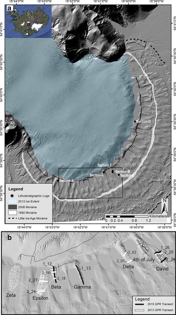
Fig. 1. (a) Map of Múlajökull including locations of the lithostratigraphic sections, 2013 ice extent, 2008 moraine, 1992 moraine and Little Ice Age (LIA) moraine. The black box shows the location of Figure 1b. Inset figure shows the location of Múlajökull on the southern margin of the Hofsjökull ice cap, central Iceland. (b) Hillshade with the different dumlins that were surveyed during the 2013 and 2015 field seasons. The white lines indicate the 2013 GPR transects whereas the black lines show the 2015 transects. Profiles shown in the paper are in bold next to their respective frequency (i.e., 1 or 2 hundred MHz) and transect-line numbers. Drumlin names are located directly below the drumlin. Hillshade is from 2 m lidar dataset from Benediktsson and others (Reference Benediktsson2016).
Múlajökull provides an opportunity to apply geophysical tools to a location where drumlin development is active and the forefield has been studied through a variety of field methods. Drumlins still under the ice (e.g., Lamsters and others, Reference Lamsters, Karušs, Rečs and Bērziņš2016; Finlayson and others, Reference Finlayson2019) allow the observation of glaciological conditions that contribute to drumlin development. Additionally, the forefield's sediments have been characterized with analyses of lithostratigraphy (Johnson and others, Reference Johnson, Schomacker, Benediktsson, Geiger and Ferguson2010; Benediktsson and others, Reference Benediktsson2016), morphology (Benediktsson and others, Reference Benediktsson2016; Hillier and others, Reference Hillier, Benediktsson, Dowling and Schomacker2018) and strain and consolidation (McCracken and others, Reference McCracken2016). One finding of these studies is that the Múlajökull drumlins are small compared to most Pleistocene drumlins but fall within the size ranges of published drumlin datasets (Johnson and others, Reference Johnson, Schomacker, Benediktsson, Geiger and Ferguson2010; Benediktsson and others, Reference Benediktsson2016; Finlayson and others, Reference Finlayson2019). Hence, by studying the formation of the Múlajökull drumlins we can gain insights into how Pleistocene drumlins formed. Using ground-penetrating radar (GPR), we add to this dataset by imaging the internal stratigraphy of seven drumlins exposed after the 1992 surge at Múlajökull and determine the stratigraphic patterns shared among them. As these drumlins have all developed under the same glacier regime, their commonalities reflect the mechanisms that lead to their development. These stratigraphic patterns are compared with predictions from various models of drumlin formation to help determine if the processes involved in each of the models are viable at this site and to thereby shed light on the subglacial environment that leads to drumlin formation.
Study site
Múlajökull is a surge-type, outlet glacier of Hofsjökull ice cap in central Iceland, and its forefield contains a wide range of geomorphological features (Fig. 1) (Jónsson and others, Reference Jónsson, Schomacker, Benediktsson, Ingólfsson and Johnson2014). The ice is constricted as it flows through a 2-km wide valley, after which it splays out to form a 4-km wide piedmont lobe. Elevation of the exposed forefield ranges from 588 to 647 m.a.s.l., with the lower elevations near the Little Ice Age (LIA) terminal moraine (Benediktsson and others, Reference Benediktsson2015). On-ice radar surveys indicate that Múlajökull flows into a 165 m deep basin (475 m.a.s.l.) before rising to the present-day glacier margin (640 m.a.s.l.) (Björnsson and others, Reference Björnsson, Pálsson, Sigurđsson and Flowers2003; Lamsters and others, Reference Lamsters, Karušs, Rečs and Bērziņš2016; Sigurkarlsson, Reference Sigurkarlsson2018). The forefield is dominated by till with some interbedded outwash packages (Benediktsson and others, Reference Benediktsson2016). A total of 143 exposed drumlins have been mapped and are overlain with crevasse-squeeze ridges and flutes (Benediktsson and others, Reference Benediktsson2016; Ives and Iverson, Reference Ives and Iverson2019). Múlajökull has surged, on average, once every 10–20 years since observations first began in 1924 (i.e., 1924, 1954, 1966, 1971, 1979, 1986, 1992 and 2008 CE), with the greatest surges resulting in 200–400 m of ice advance and often depositing an end moraine at the glacier's post-surge terminus (Jónsson and others, Reference Jónsson, Schomacker, Benediktsson, Ingólfsson and Johnson2014; Benediktsson and others, Reference Benediktsson2016) (Fig. 1). Some drumlins at the margin of Múlajökull are only partially exposed by ice. On-ice radar surveys show that these drumlins extend beneath the ice and are therefore being affected by ongoing modern-day ice motion (Finlayson and others, Reference Finlayson2019).
Lithostratigraphic sections recorded at six locations indicate that the till units in the upper three meters of the drumlins are separated by erosional contacts and that higher till units truncate the lower units creating angular unconformities (see Figs. 3 and 4 from Johnson and others, Reference Johnson, Schomacker, Benediktsson, Geiger and Ferguson2010 and Fig. 7 from Benediktsson and others, Reference Benediktsson2016). These unconformities are found predominantly along the drumlins' heads (i.e., stoss sides) and flanks, suggesting that erosion was concentrated in these regions (Benediktsson and others, Reference Benediktsson2016). In an outcrop near the crest (i.e., the high point of the drumlin's long axis) of 4th of July drumlin that is oriented perpendicular to its long axis, exposed beds strike parallel to the drumlin's long axis and dip in the direction of the local drumlin surface slope (Benediktsson and others, Reference Benediktsson2016). This bed attitude suggests the till units conform to the convex surfaces of the drumlins. Distinct basal till units that generally conform to the drumlins' surfaces are traceable from the ice margin to the end moraines of the 2008 and 1992 surges and are interpreted as having been deposited by these surges (Benediktsson and others, Reference Benediktsson2016).
Methods
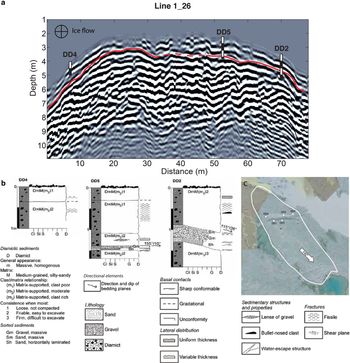
GPR data were collected and correlated with published and new stratigraphic sections to provide context for observed radar reflectors (Johnson and others, Reference Johnson, Schomacker, Benediktsson, Geiger and Ferguson2010; Benediktsson and others, Reference Benediktsson2016). A direct correlation was possible between five logs completed on drumlin David (Section-E in Fig. 1) and a 100 and 200 MHz echogram. The logs were collected along the ice-proximal and ice-distal banks of a 17 m wide ravine that bisects the drumlin laterally. The 200 MHz profile was collected on the south side of the ravine and ran along logs DD1 and DD3, whereas the 100 MHz profile was collected on the north side of the ravine along logs DD2, DD4 and DD5. Both profiles run perpendicular to the drumlin's long axis. Additional stratigraphic sections reported in Benediktsson and others (Reference Benediktsson2016) and Johnson and others (Johnson and others, Reference Johnson, Schomacker, Benediktsson, Geiger and Ferguson2010) were compared with nearby GPR lines to aid in their interpretation.
Lithostratigraphy was logged on excavated sections. Following the method of Krüger and Kjær (Reference Krüger and Kjær1999), the unit correlation was based on grain size, clast concentration, matrix composition, clast/matrix relationship, matrix consistency, deformation structures and stratigraphic position. Shape, roundness and texture of clasts were estimated in the field. Strikes and dips of beds were determined from measured apparent dips at multiple locations within a section.
In 2013, six exposed drumlins were surveyed along transects totaling 19.3 km. Data were collected using a GSSI (Geophysical Survey Systems Inc.) GPR with 200 MHz antennas, which imaged the subsurface to depths up to 4 m. Antenna spacing was fixed at 1 m, and trace spacing was set to every 2 s. Data were then resampled to a spatially averaged scale of every 0.2 m, with assistance from a L1 band only GPS and onboard position logger. The sampling interval of the GPR was 0.1955 ns, with a trace time window of 200 ns. In 2015, data were collected across transects taken on exposed and subglacial drumlins totaling 16.2 km. Four exposed drumlins were surveyed, three of which were also surveyed with the 200 MHz GPR array in 2013. Data were collected using the PulseEKKO PRO 100A system from Systems & Software, Inc. with 100 MHz antennas, imaging the subsurface to depths up to 8 m. Antenna spacing was fixed at 1 m, and trace spacing was 0.25 m. The sampling interval was 0.8 ns over a time window of 499 ns. Positional data were collected every 5th trace using a standalone Novatel SMART-V1 GPS antenna and synced to individual traces with a shared timestamp. Transect locations were chosen to provide a grid of lines across the drumlins, where the path was not obstructed. Combining the results of the 200 and 100 MHz antennas provided adequate resolution and depth penetration to interpret stratigraphic patterns.
In 2015, a common midpoint (CMP) survey, a technique for determining the velocity structure of the subsurface (see Annan, Reference Annan and Jol2003), was conducted on drumlin Gamma (Fig. 1) to estimate the root-mean-square velocity, vertical and lateral resolutions, and relative permittivity of the sediments. This allowed echograms in both years to be reliably processed. The CMP survey atop drumlin Gamma displayed a root-mean-square velocity of 0.083 m ns−1. This velocity corresponds well with velocities recorded in other modern glacial environments in Iceland (e.g., Kjær and others, Reference Kjær, Sultan, Krüger and Schomacker2004; Benediktsson and others, Reference Benediktsson, Ingólfsson, Schomacker and Kjær2009), and equates to a relative permittivity value of 13, which is typical of till and consistent with the lithostratigraphic logs collected in the Múlajökull forefield (Benediktsson and others, Reference Benediktsson2016). For the 100 and 200 MHz antennas, a vertical resolution was ~0.2 and ~0.1 m and the minimum lateral resolution was 1.8 and 0.9 m, respectively.
Data processing
Echogram data were post-processed to help interpret stratigraphic layers. Processing steps were conducted in the following order: signal position adjustment, dewow filtering, Stolt frequency-wavenumber (F-K) migration, background average subtraction, spreading exponential compensation (SEC) gain control, bandpass filtering with cutoff frequencies of 50 and 130% of the antenna center frequency, dynamic range reduction and elevation correction. For a review of these processing steps, see Annan, Reference Annan and Jol2003. The data were processed using the EKKO Project suite and scripts written in MATLAB.
Three-dimensional (3-D) models were developed for drumlins 4th of July, David, and Beta, based on the 100 MHz GPR data (Fig. 1). Reflectors that could be correlated across multiple radar lines were used to create 3-D layers whose apparent dip was measured along the drumlins' long axes. Owing to the convex shapes of reflectors, the along-flow component of dip is reported for comparison with along-flow dips predicted by various models. Dips in the down-ice direction are considered to have positive values, with negative values representing dips in the up-ice direction. We report the 3-D results of only the 100 MHz models, as the 200 MHz models provided no additional insights.
Results
Correlation with stratigraphic logs
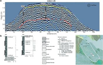
Echograms collocated with five lithostratigraphic logs illustrate that the GPR profiles detected many of the stratigraphic features apparent in the logs. Logs DD1–DD5 are located near drumlin David's crest (Figs 2, 3). The 200 MHz profile (line 2_25) shows the upper till unit present in the center of the drumlin, denoted with a yellow line, that terminates at an overlaying bed in an unconformity near the drumlin's flanks before reaching log DD1 (Fig. 2). The gravel bed present at ~2 m depth in log DD1 matches the depth of a coherent reflector in the echogram, denoted with a red line. This reflector is laterally continuous across the profile and likely extends below log DD3. The 100 MHz profile (line 1_26) displays a strongly coherent reflection at a depth similar to the gravel beds in logs DD5 and DD2 (Fig. 3). The lateral extent of the strong reflector suggests the gravel beds, and/or a sharp basal contact, in DD5 and DD2 are connected and extend laterally beyond the log locations. The GPR shows that the upper till units have a convex shape that mimics the shape of the drumlin profile, in agreement with beds along the flanks striking parallel to drumlin long axes (Benediktsson and others, Reference Benediktsson2016). Contacts in the upper 0.5 m of the logs could not be resolved due to ground and air wave interference. The additional reflectors of the echograms are likely the result of slight variations in water content, clay content, or grain-size distribution, which are commonly not visible when logging lithostratigraphy (Martinez and Byrnes, Reference Martinez and Byrnes2001; Annan, Reference Annan and Jol2003), or represent till units below the lithostratigraphic logs.

Fig. 2. Correlation between (a) 200 MHz echogram (line 2_25) and (b) stratigraphic logs DD1 and DD3 of Section-E and on drumlin David (see Fig. 1b for echogram location). The aerial photo (c) shows the location of each of the logs in the field. The echogram is along the ice-distal end of the stream cut and runs perpendicular to the mean ice flow direction. Log symbology in this and other logs in the paper is according to Krüger and Kjær (Reference Krüger and Kjær1999).

Fig. 3. Correlation between (a) 100 MHz echogram (line 1_26) and (b) stratigraphic logs DD2, DD4 and DD5 of Section-E and on drumlin David with the (c) log locations (see Fig. 1b for echogram location). Echogram is along the ice-proximal end of a stream cut and runs perpendicular to the mean ice flow direction.
Longitudinal GPR profiles
Radar profiles demonstrate a systematic dip pattern of imaged beds along the longitudinal axes of drumlins when compared to their local surface slopes (Figs 4, 5). Figure 4 shows unconformities over the full length of drumlin Beta but are more pronounced towards the crest and head of the drumlin. On drumlin Gamma (Fig. 5), unconformities are less abundant, with only a few apparent near the drumlin crest. In both drumlins, beds found in the lee side are more continuous and onlap (i.e., when shallow dipping strata terminate against a more steeply dipping bed) the shorter steeper beds near the crest. Some steep beds (red lines) near the head and crest are truncated by shallower dipping beds (green and blue lines) or terminate at the surface (Figs 4, 5). Additionally, near the drumlin tails, both drumlins show up-ice dipping reflectors. No two drumlins have the exact same stratigraphy, but many stratigraphic features are shared among drumlins. We focus on identifying these shared features, as they are more likely to reflect important formation processes. Additional longitudinal profiles can be found in supplementary material (Fig. S2–S3).
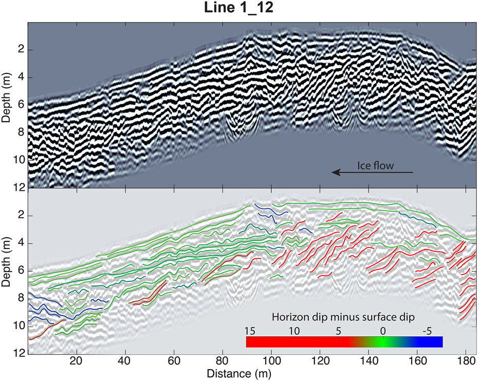
Fig. 4. Longitudinal profile of drumlin Beta (see Fig. 1b for location) measured with 100 MHz antennas (line 1_12). Reflector colors represent the difference between bed dips and surface dips above the bed's center-point. Ice margin is to the right of figure.

Fig. 5. Longitudinal profile of drumlin Gamma (see Fig. 1b for location) measured with 100 MHz antennas (line 1_15). Reflector colors represent the difference between bed dips and surface dips above the bed's center-point. Ice margin is to the right of figure.
3-D models were created for the three drumlins (i.e., 4th of July, Beta, and David) with sufficient internal reflector correlation. The mean bed dips were compared with the local dip of drumlin surfaces, both measured along the drumlin long axes (Fig. 6). Note that the x-origin in Figure 6 is at the drumlin crest and that most reflectors displayed a nearly uniform attitude. However, some reflectors were convex, and for those, we report the mean dip at the reflectors' centroid. In general, near the heads of drumlins (negative x-axis values), the internal beds dip 2°–5° steeper than the drumlin surfaces. Moving toward the lee sides (positive x-axis values), the dips of drumlin surfaces increase such that the differences between the surface dips and bed dips become smaller (Figs 4, 5). Notably, the lower left quadrant in Figure 6d is nearly empty, indicating that the internal beds are consistently steeper down-ice than the surfaces on all of the drumlin heads. These patterns are apparent in Figures 4, 5, as shown by the colors of the interpreted reflectors, and help highlight the common longitudinal stratigraphic trends of the drumlins. No significant correlation was found between dip and depth.

Fig. 6. Difference of 3-D bedding dip measurements and the dip of the drumlin surface above the bed's centroid as a function of distance from the drumlin crest for drumlins 4th of July, Beta, and David (plots a, b and c, respectively). Larger dip differences represent larger contrasts between the along-flow dips of the beds and drumlin surface (negative values are where the down-glacier surface dip is larger than the horizon dip). Negative values on the x-axis are closer to the ice margin. Plot d shows aggregated results for the three drumlins.
Transverse GPR profiles
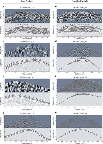
At the lee sides of drumlins, transverse echograms show a pattern of laterally continuous beds, whereas, near the crests and heads, beds terminate near the surface along the flanks. The echograms of Figure 7 show profiles collected near the lee sides (left column) and crests or heads (right column) of four drumlins with 100 MHz (Figs 7a, 7b) and 200 MHz (Figs 7c–7h) antennas. Note that the profile shown in 7b (line 1_26) is the same profile used in Figure 3. Generally, profiles collected on lee sides display bedding conformable to surfaces of drumlins across their widths, whereas echograms collected near crests and heads show the upper till units terminating near the surfaces and are interpreted as either unconformities exposed at the surface (i.e., subaerial unconformities) or truncations. Whether there is a truncating till unit at the surface, as seen in Benediktsson and others, Reference Benediktsson2016, is uncertain from the echograms because of ground and airwave interference in the upper 0.5 (100 MHz) and 0.25 m (200 MHz) of the echograms obscure very shallow layers. In contrast, in Figure 7b, an unconformity with overlying beds dipping more steeply than those below it is visible at depth. Additional transverse profiles are available in the supplemental material (Fig. S4).
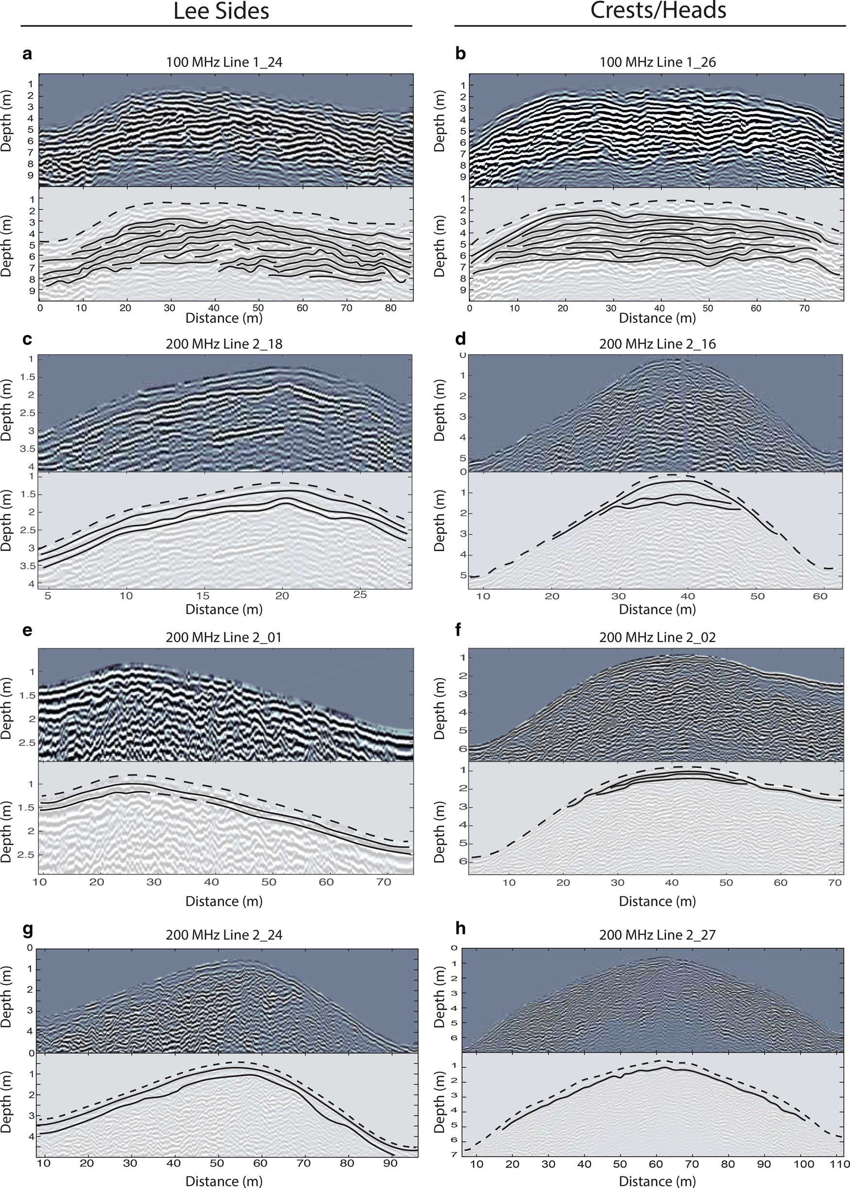
Fig. 7. Transverse profiles of four drumlins at their lee sides (left column) and at their crests and heads (right column). (a, b) 100 MHz profiles from drumlin David. (c, d) 200 MHz profiles from drumlin Beta. (e, f) 200 MHz profiles from drumlin Delta. (g, h) 200 MHz profiles from drumlin Epsilon.
Discussion
All drumlins surveyed exhibit distinct diamicton layers. Radar profiles reveal several common structural characteristics (Fig. 8) that bear on processes of drumlin development at this site: (1) beds within the drumlins generally dip down-ice; (2) beds at the heads and crests of the drumlins lie at angles to the surface, whereas along-flow dips of beds lie parallel or subparallel to lee surfaces; (3) uppermost till layers are fairly conformable along lee sides but exhibit truncations or unconformities near drumlin crests and heads. A schematic illustration of the stratigraphic features common to the drumlins is presented in Figure 8. Note that this schematic does not attempt to illustrate unique features of individual drumlins as they are unlikely to indicate the common processes that lead to the development of all the studied drumlins.

Fig. 8. Schematic model of the shared stratigraphic patterns of the drumlins at Múlajökull. These patterns include down-ice dipping beds across the drumlin, beds at the heads and crests of the drumlins lie at angles to the surface and the uppermost till layers are fairly conformable along lee sides but exhibit truncations or unconformities near drumlin crests and heads.
GPR observations support that the drumlins at Múlajökull are not the result of only erosion, but rather they are developed through a combination of erosion and deposition in agreement with lithostratigraphic, geomorphologic and geotechnical data (Johnson and others, Reference Johnson, Schomacker, Benediktsson, Geiger and Ferguson2010; Benediktsson and others, Reference Benediktsson2016; McCracken and others, Reference McCracken2016). Drumlin formation from only erosion is a possible end member in many drumlin models (Boulton, Reference Boulton, Menzies and Rose1987; Shaw, Reference Shaw2002; Stokes and others, Reference Stokes, Fowler, Clark, Hindmarsh and Spagnolo2013a, Reference Stokes2013b; Iverson and others, Reference Iverson2017). These model scenarios would require that the stratigraphy observed in the GPR and lithostratigraphic logs be deposited prior to drumlinization. Pre-drumlinization depositional settings that could produce widespread down-glacier dipping beds like those observed include proglacial braided stream networks or lacustrine deltas. Although these water-laid deposits cannot be definitively ruled out, the predominance of till to depths up to 5 m (See Fig. 7 in Benediktsson and others, Reference Benediktsson2016) and the conformity of till layers on the drumlin lees, apparent in the transverse echograms (Fig. 7), suggests that the dipping reflectors up to 5 m depth are likely not fluvial foresets (Costello and Walker, Reference Costello and Walker1972; Smith and Ashley, Reference Smith, Ashley, Ashley, Shaw and Smith1985; Miall, Reference Miall1996; Bridge and Lunt, Reference Bridge, Lunt, Smith, Best, Bristow and Petts2006). Beyond these depths, the reflectors may be interpreted as continuation of the till deposits or as other bedded layers, such as fluvial deposits. Furthermore, Benediktsson and others (Reference Benediktsson2016) observed that tills deposited during the 1992 surge were conformable to each other but truncated lower till units, suggesting modern deposition in the Múlajökull forefield. Thus, invoking only erosional mechanisms of pre-drumlin dipping layers to explain the drumlin stratigraphy is unlikely based on the field data.
The observed stratigraphic patterns indicate that net deposition occurred predominantly on the lee sides of the drumlins, whereas net erosion occurred near the flanks and heads of the drumlins. This pattern is apparent from bed truncations on the drumlin flanks and heads (indicating erosion; see Payton, Reference Payton1977) and from conformable bedding on the lee sides (indicating deposition) (Fig. 7). Morphometric observations by Benediktsson and others (Reference Benediktsson2016) and Hillier and others (Reference Hillier, Benediktsson, Dowling and Schomacker2018) suggest increased elongation ratios with time under the ice. A combination of net erosion on the drumlin flanks and heads with net deposition along the lee sides could increase their elongation ratios if deposition on lee sides exceeds erosion on heads.
The lithostratigraphic observations combined with the GPR results provide sufficient evidence to test whether some quantitative models of drumlin formation can explain drumlin development at Múlajökull. In one family of models, shear instability at the till bed of a glacier drives drumlin formation (Hindmarsh, Reference Hindmarsh1997, Reference Hindmarsh1998a, Reference Hindmarsh1998b; Schoof, Reference Schoof2007; Fowler, Reference Fowler2009, Reference Fowler2010; Fowler and Chapwanya, Reference Fowler and Chapwanya2014). In the shear instability model the assumption is made that till behaves as a viscoplastic fluid and that increased normal stresses on the stoss sides of till bumps lead to increased shear stresses. The till flux caused by shear is assumed to be proportional to the increase in shear stress, forcing a larger flux of till into the bump than out of it and thus causing it to grow. In recent models of this kind, relief transverse to ice flow is driven by deformation of till toward shallow, subglacial water layers in intervening swales (between the bumps), giving the proto-drumlins a 3-D shape (Fowler and Chapwanya, Reference Fowler and Chapwanya2014; Fannon and others, Reference Fannon, Fowler and Moyles2017). Such lateral flow of till, if in excess of the flux of till supplied from upstream by bed deformation, could cause erosion on drumlin flanks. However, whether the model can actually result in such behavior and the associated formation of an erosional surface has not been demonstrated. Moreover, till density measurements, which provide patterns of past effective stress (normal stress minus pore-water pressure) on basal tills, indicate lower effective stresses on the drumlins than in the swales (McCracken and others, Reference McCracken2016). Thus, the effective-stress gradients necessary to drive till toward swales, as proposed by the shear instability model, are in the opposite direction of those inferred from the measured till density gradients (McCracken and others, Reference McCracken2016). Also, as emphasized by Fannon and others (Reference Fannon, Fowler and Moyles2017), the bed-shear instability model, because it does not consider high-discharge, turbulent water flow beneath glaciers, is not formulated to be applicable to temperate glaciers such as Múlajökull.
Boulton's model (Boulton, Reference Boulton, Menzies and Rose1987) for drumlin formation attributes the formation of the drumlins to a bed consisting of sediments with spatially variable strain rates. As a glacier flows over the heterogeneous sediments, zones with finer, less hydraulically permeable, sediment are predicted to shear towards zones of coarser, better-drained sediment, forming a drumlin. Boulton refers to these fine and coarse sediment zones as A and B horizons, respectively. The upper till units that drape the drumlins at Múlajökull (Figs 4, 5, 7) have experienced substantial shearing (McCracken and others, Reference McCracken2016) and could be the highly strained A-horizon. However, a B-horizon, which we expect to produce a widespread strong reflector associated with coarser sediment, was not observed. Lithostratigraphic logs reached up to 5 m below the drumlin surface (see Benediktsson and others, Reference Benediktsson2016) and found only isolated packages of gravel at variable depths that quickly tapered off. It is unclear from the GPR transects how common these gravel packages are within the forefield due to the limited number of outcrops. However, the sparsity of the observed gravel beds in the available logs suggests that if there exists a B-horizon within the drumlins it is likely partially composed of diamicton. Consequently, Boulton (Reference Boulton, Menzies and Rose1987) predicts that for A and B horizons with only minor strain-rate variations (as would be the case if the B-horizon were one of the logged diamicton units), folding would occur in the drumlins. However, folding was not observed in either the GPR or the lithostratigraphic observations. For this reason, and because coarser drumlin centers would be subject to higher effective stresses than intervening swales – the opposite of that observed by McCracken and others (Reference McCracken2016) – the bed-heterogeneity model is not well supported at this site.
The drumlin model of Iverson and others (Reference Iverson2017) was developed based on field observations at Múlajökull, and its predicted stratigraphy is the most consistent with our observations. Iverson and others (Reference Iverson2017) postulate that deposition occurs during surging events, owing to sediment moved downstream by bed deformation and sediment released from ice during melting of the glacier sole. In contrast, erosion occurs during quiescent glacier flow, owing to gradients in effective stress caused by the distribution of ice pressure during a basal slip and channelized water flow at the bed. Uniform deposition during surging combined with concentrated erosion on heads and flanks of drumlins lead to net till aggregation on lee sides and net erosion along flanks and heads (Benediktsson and others, Reference Benediktsson2016; McCracken and others, Reference McCracken2016; Iverson and others, Reference Iverson2017). Although Iverson and others (Reference Iverson2017) used a longitudinal GPR transect from drumlin Epsilon (not included in this paper), as a reference for model development, both the transverse and longitudinal stratigraphic predictions made by Iverson and others (Reference Iverson2017) are consistent with the stratigraphy of the surveyed drumlins presented in this paper. This model, unlike the shear-instability and bed-heterogeneity models, is also consistent with spatial gradients in effective stress inferred from till densities (McCracken and others, Reference McCracken2016).
The model of Iverson and others (Reference Iverson2017) can provide some insight into the morphology and formation of Pleistocene drumlin fields. The model postulates that drumlin formation occurs by the previously described erosional and depositional mechanisms for surging glaciers and by only erosion for nonsurging glaciers. Comprehensive reviews on the internal compositions and structures of drumlins suggest the majority of drumlins are formed in erosional regimes (e.g., Menzies, Reference Menzies1979; Stokes and others, Reference Stokes, Spagnolo and Clark2011; Vreeland and others, Reference Vreeland, Iverson, Graesch and Hooyer2015; Eyles and others, Reference Eyles, Putkinen, Sookhan and Arbelaez-Moreno2016). However, the model requires an initial undulation, bounded by subglacial water channels, that initiates drumlin growth. Additionally, alternative erosional mechanisms, such as turbulent water flow in channels, may lead to erosional and depositional patterns not included in the current model. Inclusion of these alternative sediment transport mechanisms, along with an exploration of initial conditions that lead to drumlin growth, could improve the model.
Previous studies of drumlin morphologies have suggested that drumlins are part of a continuum of subglacial bedforms (e.g., Rose, Reference Rose1987; Ely and others, Reference Ely2016; Hart and others, Reference Hart, Clayton, Martinez and Robson2018). The model of Iverson and others (Reference Iverson2017) can provide a potential explanation for the highly variable morphologies apparent in some drumlin fields (Ely and others, Reference Ely2016). Benediktsson and others (Reference Benediktsson2016) observed that drumlins inside the 1992 moraine (Fig. 1) had a greater elongation ratio than drumlins outside the 1992 moraine. This observation, combined with the patterns of deposition and erosion at this site (Fig. 8), corroborate the predictions of the model of Iverson and others (Reference Iverson2017) that drumlins will tend to become more elongated over time. Additionally, the model suggests that the wide range of drumlin morphologies found in some localities with nonsurging glaciers could (e.g., Colgan and Mickelson, Reference Colgan and Mickelson1997; Clark and others, Reference Clark, Hughes, Greenwood, Spagnolo and Ng2009; Stokes and others, Reference Stokes, Fowler, Clark, Hindmarsh and Spagnolo2013a, Reference Stokes2013b) have resulted from local variations in effective pressure. Spatially variable effective pressure resulting from diverse patterns of subglacial channels or from different sediment properties could cause spatial variations in hydraulic potential at the base of the glacier. These variations would cause erosion rates to differ spatially and alter resultant drumlin morphologies. Further testing of this model by comparing its predictions to detailed observations of stratigraphy (with GPR and lithostratigraphic logs), till densities, and clast fabrics at other sites, specifically at sites with nonsurging glaciers, could provide a better understanding of the processes that form drumlins.
Conclusions
The recently exposed drumlin field at Múlajökull, Iceland, provides a unique opportunity to study drumlin formation. Through GPR echograms the internal stratigraphy of seven drumlins was observed and analyzed. Echograms collected transverse to the long axes of drumlins display beds terminating near the surface along the drumlin flanks. Longitudinal profiles display horizons that dip down-glacier along drumlin long axes. These beds are steeper than drumlin surfaces at drumlin heads but become shallower compared to the surfaces on lee sides (Fig. 6). Longitudinal profiles also display truncation of these dipping beds at the crests and heads of drumlins. These results are best explained by the quantitative model proposed by Iverson and others (Reference Iverson2017), which explicitly predicts bedding orientations and truncations of beds on the flanks and heads of drumlins. These observations reveal attributes where the stratigraphy was previously unknown (e.g., at the heads and lees) and show the many shared attributes among the surveyed drumlins. This study also demonstrates the utility in combining GPR with lithostratigraphic observations in the field of glaciology. Wider use of GPR coupled with lithostratigraphic observations in the glacial geological community could expand data on drumlin internal structure to test models and contribute to a more accurate understanding of the processes beneath glaciers.
Data
The GPR data presented in this paper archived online at http://digital.library.wisc.edu/1793/80254
Supplementary material
The supplementary material for this article can be found at https://doi.org/10.1017/jog.2020.50.
Acknowledgements
We thank Flavien Beaud, Ali Graham, Hester Jiskoot and an anonymous reviewer for their helpful comments. Their feedback resulted in an improved manuscript. This work was supported by an NSF EAR grant (1225812 to NRI), grants from the Energy Research Fund of Landsvirkjun, Iceland, and the Royal Physiographic Society in Lund, Sweden, (to ÍÖB), the BGS-NERC Iceland Glacier Observatory Project (to AF), and the University of Wisconsin-Madison Geoscience Department.


 Open access