


Introduction
This paper presents the development and application of a solution procedure designed to describe the deformation of snow-packs due to creep and glide. An element for such a solution was first developed by Reference Brown and EvansBrown and Evans (1975), but this element was restricted to the case where deformation was plane, that is, for motion down a wide slope of constant gradient. The element described here conforms to the same neutral zone kinematics as did the Brown− Evans model but permits the general motion to vary both down and across the slope. This allows a more general type of problem to be solved, for example, that of the creep and glide of snow on slopes with arbitrary arrangements of static defense structures. The main advantage of such a procedure is that it will permit an approximate theoretical investigation of the various static avalanche defense arrangements.
In the first part of this paper the element is developed. It is then used to investigate further the continuous barrier problem and to examine briefly some other barrier arrangements. The paper concludes with some discussion into applications of the work.
The Element
Observations into the creep and glide of snow in the Cascade Mountains of the United States of America (Reference Brown, Brown, Evans and LaChapelle.Brown and others, 1972; Reference McClungMcClung, unpublished) show that the creep profile throughout the thickness of the snow is approximately linear. Such motion has also been observed in the Swiss Alps (Haefeli in Reference Bader, Bader, Haefeli, Bucher, Neher, Eckel, Thams and Niggli.Bader and others, 1939, p. 143).
A calculation of forces on rigid obstacles in the glide path requires, in general, some approximate numerical procedure, so it appears reasonable to make use of a method which restricts motion everywhere to conform to that observed in the neutral zone.
The snow is assumed to be linearly viscous under conditions of steady creep and to be isotropic but non-homogeneous. The creep modulus varies linearly with depth and is zero at the upper surface. The inhomogeneity may either be a material property resulting from some deposition process, or may be stress induced, that is, for an isotropic material the creep modulus may depend linearly on hydrostatic stress. No field evidence is available to favour either law; both are considered here but the former is mainly used.
The element is a triangular prism extending the depth of the snow-pack. Sections which are initially plane remain plane during deformation, and the motion thus conforms to the observed kinematics in the neutral zone and at rigid barriers.
For all subsequent calculations the snow thickness and density are taken to be constant, the glide law is taken to be linear, in other words, the restraining tangential traction is proportional to the glide velocity and the glide modulus β is taken to be constant. The steady creep behavior is characterized by the viscous analogs of Young’s modulus (the creep modulus E) and Poisson’s ratio v. The behavior of E was described above, v is taken to be constant. The time during which the motion is studied is taken to be short enough so that geometry changes may be ignored.
Boundary conditions prescribe either zero velocity, zero traction, or velocities which are proportional to traction, so the problem is equivalent to one of linear elasticity and elementary finite-element procedures are applicable. The pentahedral element used is shown in Figure 1. The z coordinate is normal to the slope and the depth of the pack is h. The displacement is such that the strain in any section perpendicular to the z-axis is constant and strains vary linearly in the z-direction. Only motion in the z-plane is considered; any settlement and resulting tangential force or obstacles may be considered separately. The 12 X 12 element stiffness-rate and glide-stiffness-rate matrices are given in the Appendix. Their calculation is lengthy but straightforward Reference Langdon(Langdon, unpublished) and details are not shown here. Specific examples are now given; they all involve uniform slopes.

Fig. 1. The element used in the general solution.
Continuous Barrier Problems
If the x-axis is up the slope, referred to in Figure 1, the element is characterized by
while the motion requires that

and the 4 degrees-of-freedom element is essentially equivalent to that of Reference Brown and EvansBrown and Evans (1975). This arrangement permits the effect of the kinematic restriction to be investigated by comparison with a finite-element, plane-strain formulation (Reference McClungMcClung, unpublished). The elements used are shown in Figure 2 and the resultant barrier force is used as a basis of comparison (there is also, in general, a resultant barrier moment which is not discussed here).
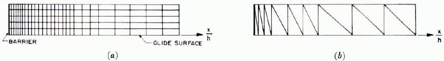
Fig. 2. Element arrangements for continuous barriers. (a) Elevation of the two-dimensional arrangement. (b) Plan of two-dimensional full-depth arrangement (both diagrams are drawn to the same scale).
The barrier force F may be expressed as
where ρg is the snow density and
In Equation (2)![]() is the effective Poisson’s ratio, α is the slope angle and c 1 is a measure of the force due to creep and glide. The first term on the right-hand side of Equation (2) is due to static pressure (Reference Brown, Brown, Evans and LaChapelle.Brown and others, 1972) and c 1 is most conveniently represented in terms of ν and A, the relative neutral-zone stagnation depth. A, in turn, may be shown to be given by the relation
is the effective Poisson’s ratio, α is the slope angle and c 1 is a measure of the force due to creep and glide. The first term on the right-hand side of Equation (2) is due to static pressure (Reference Brown, Brown, Evans and LaChapelle.Brown and others, 1972) and c 1 is most conveniently represented in terms of ν and A, the relative neutral-zone stagnation depth. A, in turn, may be shown to be given by the relation
where
is the glide modulus at depth z Reference Langdon(Langdon, unpublished).
An extensive parameter study by Reference LangdonLangdon (unpublished) for the full-depth element has found c 1 to be given accurately by the empirical relation
in the ranges
The values found for c 1 are slightly higher than those from the finite-element, plane-strain program, the greatest difference in c 1 being 8%. Comparison with the finite-element plane-strain solution also shows that although some deviation from the linear creep profile occurs in the back-pressure zone, this deviation is relatively small (not exceeding 10%) and is insignificant except near the barrier. The full-depth element also gives back-pressure zones and glide profiles which are nearly identical to the plane-strain procedure.
The agreement between solutions is not quite so close for the stress-induced inhomogeneous constitutive law Reference Langdon(Langdon, unpublished). This is because, for the plane-strain solution, the variation in modulus can be more closely approximated than for the solutions of the full-depth element for which the modulus can only be made dependent on the average hydrostatic stress over the entire depth of the snow. Because the z-direction stress σz is not determined in this solution, the hydrostatic stress, in turn, cannot be accurately determined.
Pole Barriers
These are idealized as a line barrier normal to the slope. Figure 3 shows a 120-element arrangement which was used for these problems. In order to obtain good approximations for forces and velocities it was necessary to have small elements near the pole.

Fig. 3. Element arrangement for pole barriers (shaded area contains 81 similar elements diminishing in size).
The element arrangement takes advantage of symmetry and antisymmetry. The boundary condition at the pole is zero velocity in both directions. The boundary conditions along both axes are zero y velocity and zero x traction. This boundary condition on the y-axis arises as follows: Although the entire problem is not antisymmetric, it may be thought of as the sum of two cases, (1) the uniform creep and glide, and (2) the superimposed line force at the pole to make the total velocity there zero. The x traction and y velocity for case (i) are zero everywhere, whereas case (2) is antisymmetric about the y axis and hence the x traction and y velocity are zero at the y-axis for this case. Thus the entire problem may be solved by considering the quarterspace and by using boundary conditions of symmetry about the x-axis and antisymmetry about the y-axis. The other boundary corresponding to the neutral zone has zero x-direction traction and zero y-direction velocity.
A parameter study varying A and v for the materially inhomogeneous constitutive law results in the following empirical equation for barrier force (excluding static pressure)
where
This barrier force is approximately equal to the force acting on a continuous barrier over a length of one-half the snow depth. Equation (7) is within 1% of the results for all cases studied in the range between 0 ≤ A ≤ 0.8 and 0 ≤ v ≤ 0.375.
The glide and surface velocity contours in the x-direction as well as the shear stress T xz can be closely approximated by ellipses as shown in Figure 4. As would be expected, the extent of the back-pressure zone in the x-direction is considerably less than it is for a continuous barrier. The 90% contour for A = 0.2 and v = 0.2 for the pole barrier is at x = 0.51 h whereas for the continuous barrier it is at x = 1.80h. Velocity components in the y-direction as well as Tyx are small.
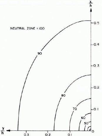
Fig. 4. Approximate contours of x-velocities and Txz for pole barrier where A = v = 0.2
Pole Barrier Restrained at the Ground only
This problem, which can be considered an approximation to a very short obstacle interrupting glide, was studied for the specific conditions A = v = 0.2. The value of c3 for this case was 15% of that for a rigid pole barrier. The xz shear stress at the barrier is actually increased by some 30%, which implies that an isolated obstacle may increase the avalanche risk if, as must be expected, this stress influences avalanche formation.
Cylindrical Barriers
Two cylindrical-barrier problems were solved using an element arrangement similar to that used for the pole-barrier problems. The snow was assumed to adhere to the barriers on all sides so that symmetry and antisymmetry boundary conditions could be used. Results were obtained for two cylinder diameters, 0.02 h and 0.06 h. Such dimensions might correspond to trees; in snow 4 m in deep the diameters corresponding to the above data are 80 and 240 mm, respectively. The velocities Txz can be approximated by ellipses as before. The eccentricity is no longer constant near the barrier, and the back-pressure zone increases with increasing barrier size. For the case A 0.2 and v = 0.2, values of c 3 in Equation (6) are 0.62 and 0.82 for diameters of 0.02 h and 0.06 h, respectively.
Discontinuous Barrier
An appoximate solution for a semi-infinite barrier was obtained using the element arrangement shown in Figure 5; 181 elements are used here. Symmetry was not used because of velocity discontinuity conditions which were permitted across the barrier. In order to arrive at realistic boundary conditions, all surfaces were taken to be traction free except for the up-slope side of the barrier where the y-direction velocity was taken be zero, and at the outer boundary aty = 2h where the x-direction velocity was set equal to zero. These boundary conditions permit a separation between the snow and the barrier on the down-slope side of the barrier.

Fig. 5. Element arrangement for discontinuous barrier (shaded area contains 505 similar elements diminishing in size)
In Figure 6, the barrier force is shown for the particular case A = v = 0.2. The force intensity is large near the end of the barrier (theoretically there is a singularity here). The average force values are 30Q, for the first 0.1 h along the barrier and 1.6(2. over the first h of barrier length (Q is the force intensity, neglecting static pressure, for the same creep and glide conditions on a continuous barrier). It may be seen, however, both from this Figure and from Figure 7, which shows the 80 and 90% value contours of the neutral zone, that the continuous-barrier solution describes the finite-barrier problem except in the immediate vicinity of the ends of the barrier.

Fig. 6. Force intensity near the end of a discontinuous barrier.

Fig. 7. Contours of 8o% and 90% near the end of a discontinuous barrier.
Concluding Remarks
The procedure outlined in this paper provides an effective determination of the forces due to creep and glide on barriers which are perpendicular to the slope. The present method has led to a computationally efficient procedure in that relatively few degrees of freedom are required compared with conventional finite-element arrangements. The program has been written so that it is user oriented, and a FORTRAN listing is available from the authors. For continuous barriers, the forces are in reasonable agreement with those of the Swiss guidelines. As shown by Reference Brown and EvansBrown and Evans (1975), however, the forces in the present analysis are not uniform with depth.
Experimental measurements are sparse. Those made at the Eidg. Institut far Schnee- und Lawinenforschung have been summarized by Reference SalmSalm (1977). The results are for very low glide and show considerable scatter. If v is assumed to be 0.3 the values are rather lower than those predicted here by Equations (2) and (5).
Refinement of the element is possible; for instance, a variable-height element could be developed in a manner similar to that of Brown and Evans. The present model could also be used for arbitrary slopes by modifying element densities appropriately. This, however, would not take into account geometric incompatibilities at surfaces normal to the slope.
It does not seem appropriate to develop theoretical methods further until more experimental evidence is available on the material behavior of snow in creep and glide. Indeed, field measurements show wide variations in creep and glide, thus calculations such as those given here must be used with considerable caution. Certainly, mechanisms other than those considered here must be considered in connection with avalanche defense design. For instance, in the Cascade Mountains, slab avalanches often result from the formation of depth hoar at some intermediate snow depth. This procedure will, however, provide information for static avalanche control by the techniques of forestation or ground surface modification. It has been shown that the back-pressure zone for a pole barrier can be less than the snow depth. If it is assumed that the back-pressure zones of adjacent barriers must interact for effective avalanche control, then barrier spacing would have to be less than the snow depth.
Appendix

where

where
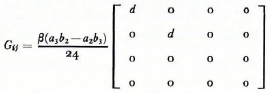
and

Discussion
B. SALM : According to Swiss experience and theoretical considerations, the force on a confined structure depends to a much higher degree on the glide factor (or stagnation depth) than the force on an unconfined structure. How do your investigations show this relationship?
R. J. EVANS: As Equation (3) shows, the force is unchanged as long as E o/β remains constant. For E o constant, β varying, the dependence on β may be deduced from the same equation.
T. LANG: Is the ratio of surface dimension to the depth dimension of your reported element a sensitive parameter for numerical stability when the ratio is small compared to unity?
EVANS: We found no sensitivity even for values of h lower than shown here.


