


Introduction
In studying river-ice fabrics, Reference LascaLasca {1971) found that many c-axes were orientated parallel to the stage, when viewed in thin section on the Rigsby universal stage. From this work it became apparent that an accessory plate was necessary to discriminate between the a- and c-axes when the orientation of the c-axis was parallel or nearly parallel to the stage. Therefore, a modification of the techniques described by Reference LangwayLangway (1958) for determining low-angle c-axis orientations in ice fabrics was necessary.
Under most conditions, ice crystals are elongate parallel to the c-axis (optic axis). In ice petrography, it is desirable, but not always possible, to orientate the individual crystals in a sample so that their optic axes are vertical. The Rigsby universal stage is used to determine the optic-axts orientations in ice.
The standard optical principles used with the universal stage on a petrographic microscope are the same as those used with the Rigsby universal stage. However, as the Rigsby universal stage is used without a microscope, no provision is made for (1) magnification, (2) use of an accessory plate, or (3) use of a collimating device (i.e. a device which restricts the field and direction of vision to a specific and limited area of the thin section).
Being hexagonal, ice (1) is uniaxial, and (2) because the refractive index measured parallel to the c-axis is greater than that measured parallel to one of the a-axes, ice crystals are optically positive. Light traveling parallel to the c-axis of an ice crystal penetrates at a lower velocity than light traveling parallel to an a-axis. Therefore, the c-axis is the slow vibration direction.
Knowing that the c-axis of ice is optically positive, the c-axis can be located by determining which of the two vibration directions of the ice crystal is slow. This is accomplished by introducing an accessory plate between the crystal and the upper polar. The accessory plate is simply a mineral of known vibration direction and corresponding optic sign (for discussion see p. 137).
In order to determine the orientation of c-axes in ice using the Rigsby universal stage, the principles of optical mineralogy must be applied to the following situations:
Situation 1. The optic axis of the ice crystal is vertical.
Situation 2. The optic axis of the ice crystal lies between the vertical position and 60° from the vertical.
Situation 3. The optic axis of the ice crystal is inclined greater than 60° from the vertical.
Recommended Procedures
Method I
The suggested procedure for orientating the optic axis is as follows:
1. Place an orientated ice thin section parallel to the north-south direction on the Rigsby universal stage (Fig. 1).

Fig. 1. Diagrammatic illustration of an ice thin section orientated parallel to flow
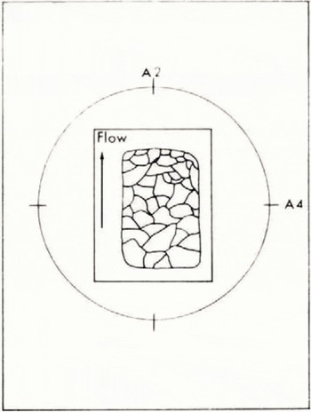
Fig. 2. Diagrammatic illustration of the initial position of an optic axis prior to rotation about the A1, axis
2. Set the A1, A2, A4 and A5 axes to the zero position.
3. Pick a crystal for study and rotate the sample about the A1 axis until extinction is obtained (Figs. 2 and 3). If total extinction occurs through 360° of rotation about the vertical axis of the microscope (A1), the optic axis of the ice crystal is orientated parallel to the vertical line of sight (situation 1).
4. Rotate the A4 axis clockwise and counter-clockwise from the zero position (Fig. 4). If illumination occurs, situation 2 applies. Return the A4 axis to zero. Proceed to step 6-A. If extinction is maintained, proceed to step 5.
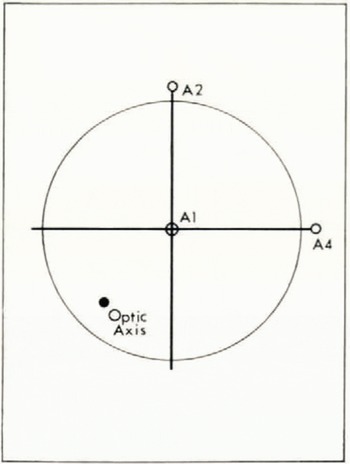
Fig. 3. Diagrammatic illustration of an optic axis after rotation to extinction about the A1 axis

Fig. 4. Diagrammatic illustration of optic-axis movement within the north-south vibration plane during rotation about the A4 axis.
5. Return the A4 axis to the zero position. Rotate the A2 axis clockwise and counterclockwise from the zero position. If illumination occurs, situation 2 applies. Proceed to step 6-B. If extinction is maintained, situation 3 applies. Return the A2 axis to zero. Proceed to method II.
6-A. Rotate the crystal 90° on the A1 axis. The c-axis is now in the north-south vibration plane.
6-B. Return the A2 axis to zero. The c-axis is now in the north-south vibration plane.
7. Rotate the crystal 45° about the A5 axis, i.e. to the position of maximum illumination (Fig. 5).
8. Rotate the crystal about the A4 axis until the crystal is in extinction (Fig. 5). The c-axis is now vertical. Readings may be taken directly from the A, and A4 axes. After appropriate corrections (Reference LangwayLangway, 1958) are made, the data may be plotted on a Schmidt net.
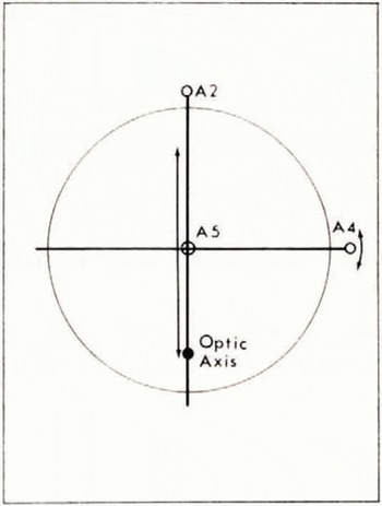
Fig. 5. Diagrammatic illustration of rotation of the optic axis to the 45° position about the A5 axis, and rotation of the optic axis to extinction about the A4 axis.

Fig. 6. Diagrammatic illustration of the crystallographic axes of an ice crystal where the c-axis is parallel or nearly parallel to the stage. The crystal remains extinct upon rotation of either A2 or A4
The method outlined above is similar to that described by Reference LangwayLangway (1958) for determination of c-axis orientations in situations 1 and 2 described above. When the optic axis of the ice crystal is nearly parallel to the stage, it is necessary to use an accessory plate to discriminate between the a- and c-axes before the location (azimuth) of the c-axis can be determined. The reasons for this are:
-
With the optic axis parallel to one of the principal vibration directions induced by the polars, extinction is produced every 90° coincident with one of the vibration directions, or four times.
-
With the optic axis parallel to one of the vibration directions, it can be rotated (by use of mutually perpendicular axes on the U-stage) either perpendicular to the north-south vibration direction or coincident to the north-south vibration direction without disrupting extinction (Fig. 6).
-
Without the aid of an accessory plate (quartz sensitive tint, gypsum plate, mica plate, etc.), it is impossible to determine which of the crystallographic axes of ice is parallel to a given vibration direction.
Use of an accessory plate
If an accessory plate with known vibration directions and known interference color is inserted parallel to the c-axis of an ice crystal, optical interference will occur. As ice is optically positive, the c-axis is the slow vibration direction of the crystal. When an accessory plate is held over the ice crystal so that the slow vibration direction of the plate coincides with the slow vibration direction of the c-axis of the crystal, constructive interference occurs and a higher-order interference color is produced.
If optical subtraction occurs when the slow vibration direction of the accessory plate is inserted parallel to a vibration direction of the crystal, the vibration direction of the crystal is then fast and one of the a-axes is observed.
All optic-sign determinations are made with the crystallographic axes of the ice crystal in the plane of the stage. The axis studied must be in the 45° position upon insertion of the accessory plate. A simple accessory plate is easily made from large flakes of muscovite mounted on a glass plate. The slow and fast vibration directions and interference colors of the muscovite can readily be determined using a standard petrographic microscope.
Method II
The suggested procedure for orientating optic axes inclined greater than 6o° from the vertical (situation 3) is as follows:
-
Rotate the crystal to extinction about the A1 axis.
-
Rotate the crystal about the A2 axis then the A4 axis. If the crystal remains at extinction upon complete rotation about the A2 and A4 axes, the c-axis must lie along either the north-south or east-west vibration direction in the plane of the stage. Return the A2 and A4 axes to zero.
-
Rotate the crystal from the extinction position to the 45° position about the A5 axis (microscope-stage axis).
-
Insert the accessory plate with its slow vibration direction parallel to the crystal axis which is now in the 45° position.
-
If addition occurs, the crystal axis in the 45° position is positive (the c-axis) and the optic axis is located.
-
If, however, subtraction occurs, the crystal axis in the 45° position is fast and therefore one of the a-axes. Because only c-axes are plotted, it is necessary to rotate the crystal 90° on the A1 axis and repeat steps 4 and 5.
-
To complete the orientation of the c-axis, it is necessary to adjust the inclination of the c-axis until it lies in the plane of the stage. This is best accomplished by rotating the A4 axis (perpendicular to the optic axis) until maximum birefringence (highest-order interference color) is obtained.
-
The c-axis is now horizontal. Readings may be taken directly from the A1 and A4 axes. After appropriate corrections (Reference LangwayLangway, 1958) are made, the data may be plotted on a Schmidt net.
Conclusions
-
Procedures outlined in method II provide positive identification of c-axis orientation when the optic axis of the ice crystal is inclined greater than 60° from the vertical.
-
In studies involving c-axis orientations inclined greater than 60° from the vertical, confusion between the a- and c-axes is eliminated.
-
The technique described requires approximately 1-2 min per crystal to determine c-axis orientation.
Acknowledgement
We wish to thank Dr G. Mursky for his helpful suggestions and review of this article.
MS. received 16 July 1970


