


Introduction
The discovery of Lake Vostok, east-central Antarctica, involved many scientists over a period of more than four decades. Reference Oswald and RobinOswald and Robin (1973) were the first to bring to light the existence of a subglacial lake beneath the Vostok region, based upon a radio-echo sounding survey. The rough dimensions of the subglacial lake were obtained by Reference Ridley, Cudlip and LaxonRidley and others (1993) from analysis of the ice-sheet surface topography. A seismic survey performed in 1964 by Russian scientists was re-analyzed, allowing the water thickness to be calculated (Reference Kapitsa, Ridley, Robin, Siegert and ZotikovKapitsa and others, 1996). The existence of a water body was confirmed by isotope studies indicating that the Vostok ice core, from 3539 m below the ice surface to its bottom, consists of refrozen ice from Lake Vostok water (Reference JouzelJouzel and others, 1999).
Measurements
During the 1999–2000 Italian Expedition, airborne ice-penetrating radar measurements were made over the Vostok–Dome C region in order to increase our knowledge of Lake Vostok and its boundary, and to contribute towards the reconnaissance of the entire area’s bed morphology. The choice of flight-lines was based on analysis of the ice-sheet surface topography (Reference Siegert and RidleySiegert and Ridley, 1998; Reference Rémy, Shaeffer and LegrésyRémy and others, 1999; Reference Siegert, Kwok, Mayer and HubbardSiegert and others, 2000) and on the Kapitsa outline of the lake (Reference Kapitsa, Ridley, Robin, Siegert and ZotikovKapitsa and others, 1996). This paper confines itself to setting forth results from the flights made over the Vostok region. The radar lines are located in Figure 1. The transects “ew2” and “ew3” over the lake run parallel to the flowlines (Reference Kwok, Siegert and CarseyKwok and others, 2000), while the transects “ew1” and “ew4” present an angle of approximately 20° and 8°, respectively. The transects “ns1” and “ns2” are roughly perpendicular to the flowlines.

Fig. 1 Location of radio-echo sounding flight-lines of Italian Expedition 1999 and of Scott Polar Research Institute (SPRI)–Technical University of Denmark (TUD)–U.S. National Science Foundation (NSF) survey (Reference SiegertSiegert, 2000). VK, Vostok station.
Radar data were acquired using an airborne 60 MHz INGV-IT digital radar, linked to a global positioning system (Tabacco and others, l999).We used a 1 μs pulse length (about 160 m ice thickness), a 20 MHz digital sampling frequency yielding an accuracy of 50 ns (∼8 m in ice). We acquired 10 traces s−1 (approximately 1 trace per 7 m at the main aircraft speed) with a time range of 64 μs. Ice thickness was calculated using a constant velocity of 168 m μs−1 (Reference Glen and ParenGlen and Paren, 1975; Reference RobinRobin, 1975; Reference Bogorodsky, Bentley and GudmandsenBogorodsky and others, 1985; Reference PatersonPaterson, 1994). Cross-checking between the intersection of east–west and north–south profiles yields thickness differences of < 10 m; the error in thickness determination along each transect is estimated at < 16 m. Bed elevation was calculated by subtracting the ice thickness from the surface elevation obtained by the European Remote-sensing Satellite-1 radar altimeter data (Reference Rémy, Shaeffer and LegrésyRémy and others, 1999).
Lake Boundary
It is well known that the reflection strengths from ice/water and ice/rock interfaces differ by >10 dB due to the values of the real part of the dielectric constant of water and rock, and to the roughness of bedrock (Reference Oswald and RobinOswald and Robin, 1973; Reference Siegert, Dowdeswell, Gorman and McIntyreSiegert and others, 1996; Reference Gorman and SiegertGorman and Siegert, 1999; Reference SiegertSiegert, 2000). For this reason the variation of reflection strength along each transect was analyzed in order to obtain the accurate position of the grounding line. To evaluate the strength variation due only to the bottom interface, we need to remove from the measured bottom reflections all those contributions caused by overlying ice.
The reflected power P R is calculated by:
where G is the antenna gain, λ is the wavelength, r is the distance, P T is the transmitted power, Q is the refractive gain, L f is the gain/loss due to the focusing/defocusing effect of surface shape and L is the total power loss, due to volume inhomogeneity (L v), ice-surface and ice-bottom scattering (L si and L sb), reflection at the ice/air and air/ice interfaces (L r), polarization (L p), medium absorption (L a) and transmission at the bottom interface (L t).
Expressing Equation (1) in dB and considering geometrical attenuation L g = 20 log(4 πr/Gλ), we obtain:

The transmitted power P T for the INGV-IT radar is 62.6 dB. The refractive gain Q and the focusing–defocusing effect L f are 3–4 dB for nearly flat reflecting surfaces (Reference Bogorodsky, Bentley and GudmandsenBogorodsky and others, 1985). The scattering loss from the ice/air interface, L si, ranges from near zero to several dB depending on surface roughness. In this work we assume a value of about 1–2 dB obtained after an averaging of raw data. Based on a preliminary elaboration of the raw data, we found that the values L v, L p and L r may be considered constant along each profile, and their total contribution is approximately 4 dB.
With these assumptions:
where L t and L sb are the two terms strictly related to the bottom interface; their sum might be considered as a relative power reflection coefficient (RPRC). Setting [RPRC] = [L t] + [L sb] we obtain:
By measuring the amplitude of the echo signals P R, and the ice thickness, we are able to calculate L g and L a, and finally RPRC. There are some problems with the calculation of L a. The absorption is given by L a = kσd, where k is a constant, σ is the conductivity dependent on temperature and depth, and d is the thickness; its estimation is influenced by errors due to uncertainty relating to the value of conductivity and to its variation with depth. We restricted the amplitude analysis to the lake and the surrounding shore; in this case, the depth difference between lake ceiling and bedrock is < 100 m, so the errors due to an incorrect value of the absorption coefficient have little bearing upon the RPRC trend along the profiles at the lake/bedrock transition. The RPRC values and the bottom morphology were subsequently used to identify the grounding line. On the east–west transects, bottom reflections with both very rough and flat morphology can be identified (Figs 2–5). On account of the reflection amplitude we are able to distinguish:
-
(1) a wide tract over the flat area, with a high and fairly constant (varying within 1 dB) RPRC value, interpreted as an ice/water interface;
-
(2) a short tract, close to the western margins of the flat area, with a very high RPRC value (roughly 4 dB higher than the previous one). This very high reflection strength is also interpreted as an ice/water interface and thus as a lake ceiling.
-
(3) surrounding tracts over a rough reflector with widely variable amplitude (varying up to 20 dB) and low reflection strength (more than 10 dB lower than the flat area). These low and irregular values are typical features of an ice/rock interface.

Fig 2. Transect “ew1”. (a) RPRC; (b) radar sections with ice thickness and two-way time (TWT); (c, d) surface and bed elevation, respectively (m a.s.l.).

Fig 3. Transect “ew2”. (a) RPRC; (b) radar sections with ice thickness and TWT; (c, d) surface and bed elevation, respectively (m a.s.l). (∇) denotes cross-point between profiles.

Fig. 4. Transect “ew3”. (a) RPRC; (b) radar sections with ice thickness and TWT; (c, d) surface and bed elevation, respectively (m a.s.l). (∇) denotes cross-point between profiles.

Fig 5. Transect “ew4”. (a) RPRC; (b) radar sections with ice thickness and TWT; (c, d) surface and bed elevation, respectively (m a.s.l.). (∇) denotes cross-point between profiles.
Similar results were obtained for the north–south profiles.
Ice Thickness
Along the transect “nsl” (Fig. 6) ice thickness over the lake increases from 3799 m (south) to 4250 m (north). We can identify three sectors with a thickening rate that decreases from ∼5.9 m km−1 (south) to ∼2.5 m km−1 (central) to ∼1 m km−1 (north).

Fig. 6. Transect “ns1”. (a) radar sections with ice thickness and TWT; (b, c) surface and bed elevation, respectively (m a.s.l.). (∇) denotes cross-point between profiles.
In each east–west transect (Figs 2–5) we distinguish three sectors:
-
(a) a western sector with a steep eastward ice thickening, located over the area with very high reflection strength. The thickening rate along the flight tracks is greater in the southern-central area (20–43 m km−1) than in the northern area (8 m km−1);
-
(b) a central sector with near-constant thickness;
-
(c) an eastern sector with sharp westward ice thickening.
Taking into account ice-thickness variation, the pressure-dependent freezing temperature at the lake ceiling and the horizontal temperature gradient were calculated for each sector, according to the equation T(p) = T(0)−0.00753p, where T is the freezing temperature at pressure p (expressed in bar) and T(0) is assumed to be 0°C (Reference Fujino, Lewis and PerkinFujino and others, 1974; Reference Souchez, Petit, Tison, Jouzel and VerbekeSouchez and others, 2000; Reference Wüest and CarmackWüest and Carmack, 2000). The temperature gradients of the western and eastern sectors are greater than those in the north-south sectors (Table 1).
Table 1. Features of the lake derived from radar transects.Thickening rate and horizontal temperature gradient are calculated from west to east and from south to north

Surface and Bed Topography
The subglacial topography surrounding the lake is highly complex and irregular; bed elevation ranges between −750 and +1000 m a.s.l. The western and eastern lake shores along the south-central area have a gradient of > 100 m km−1, and at the northern end the bedrock gradient is lower at ∼80 m km−1 (Fig. 7). Lake Vostok occupies a depression elongated parallel to the boundary between the Vostok Subglacial Highlands and the western Aurora Basin. This depression is at least 260 by 80 km, with the longer axis north-northwest–south-southeast oriented. A rift, with a possible link to a rifting system entering inland from the Amery Basin, has been proposed by Reference Leitchenkov, Verkulich and MasolovLeitchenkov and others (1998). We note that the lake-flanking bed morphology does not evidence any smoothing effects of substantial surface erosion or sedimentation processes. Hence, these indications strongly suggest that the depression developed over a relatively short geological time, most probably during the Cenozoic period (Reference Leitchenkov, Verkulich and MasolovLeitchenkov and others, 1998; Reference Dalziel, Bell and KarlDalziel, 1998).

Fig 7. Bed elevation (m a.s.l.) of the Vostok area with tracks of radar lines. Contour lines 100 m. VK, Vostok station.
Over the lake, the ice surface elevation (Reference Rémy, Shaeffer and LegrésyRémy and others, 1999) increases from 3476 m (south) to 3525 m (north), with an average northward gradient of 0.2 m km−1, while the lake-ceiling elevation decreases from −315 m (south) to −750 m (north), with an average northward gradient of −1.7 m km−1. The ratio between lake-ceiling and surface slope gradients is −8.5. Neither surface nor ceiling slope from south to north is constant, and we may distinguish three sectors (Fig. 6): sector 1, between 0 and 25 km (surface gradient 0.5 m km−1, ceiling gradient −5.9, ceiling/surface gradient ratio −11.8); sector 2, between 25 and 70 km (surface 0.3 m km−1, ceiling −2.6 m km−1, ratio −8.7); and sector 3, between 70 and 260 km (surface 0.1 m km−1, ceiling −0.9 m km−1, ratio −9.0). The values of the ratio between lake-ceiling and ice-surface gradients are consistent with the ice and lake model in hydrostatic equilibrium, where the gradients of ice/water interface must be approximately 10 times, and in the opposite direction to, the ice-surface gradient (Reference Oswald and RobinOswald and Robin, 1973). The surface and bed elevation over the central part of the lake are fairly constant on all the east–west transects.
Along the western side, over a narrow strip (<5 km long) the surface topography indicates a trough roughly 8 m deep, while the lake ceiling dips with a gradient ranging from 8 m km−1 (transect “ew4”) to 40 m km−1 (transect “ew2”). Along the eastern side, confined to the central southern part of the lake, surface topography indicates a peak about 7 m high, while the lake ceiling dips with a rate of about 15 m km−1. We may assume that these features are due to downslope and upslope motions produced by a mechanism driven by a change in ice dynamics from grounded, floating and regrounded ice (Reference Kapitsa, Ridley, Robin, Siegert and ZotikovKapitsa and others, 1996; Reference Siegert and RidleySiegert and Ridley, 1998).
Discussion and Conclusion
The amplitude analysis allowed for a definition of the nature of bottom interfaces and for unambiguous positioning of the grounding line indicated by sharp amplitude changes. Our radar data confirm the geometry of Lake Vostok derived from previous analysis, but with some slight differences, the main one being the extent of the lake. We measured a length of up to 260 km and a maximum width of 81 km. A map of surface slopes superimposed on the radar tracks showing lake reflections is given in Figure 8. Lake boundaries derived from radar measurements are highly appropriate for areas with a slope gradient of < 0.02%. It should be noted that both the surface “trough”, running along the western lake shores, and the “peak” along the eastern shores (slope gradient ranges: 0.02–0.1% and 0.1–0.2%) are to be included in the lake body. The lake area, calculated on the basis of surface area with slope < 0.02%, is about 14 000 km2; this value is affected by some uncertainties due to the location of the northern boundaries, and represents the minimum area.
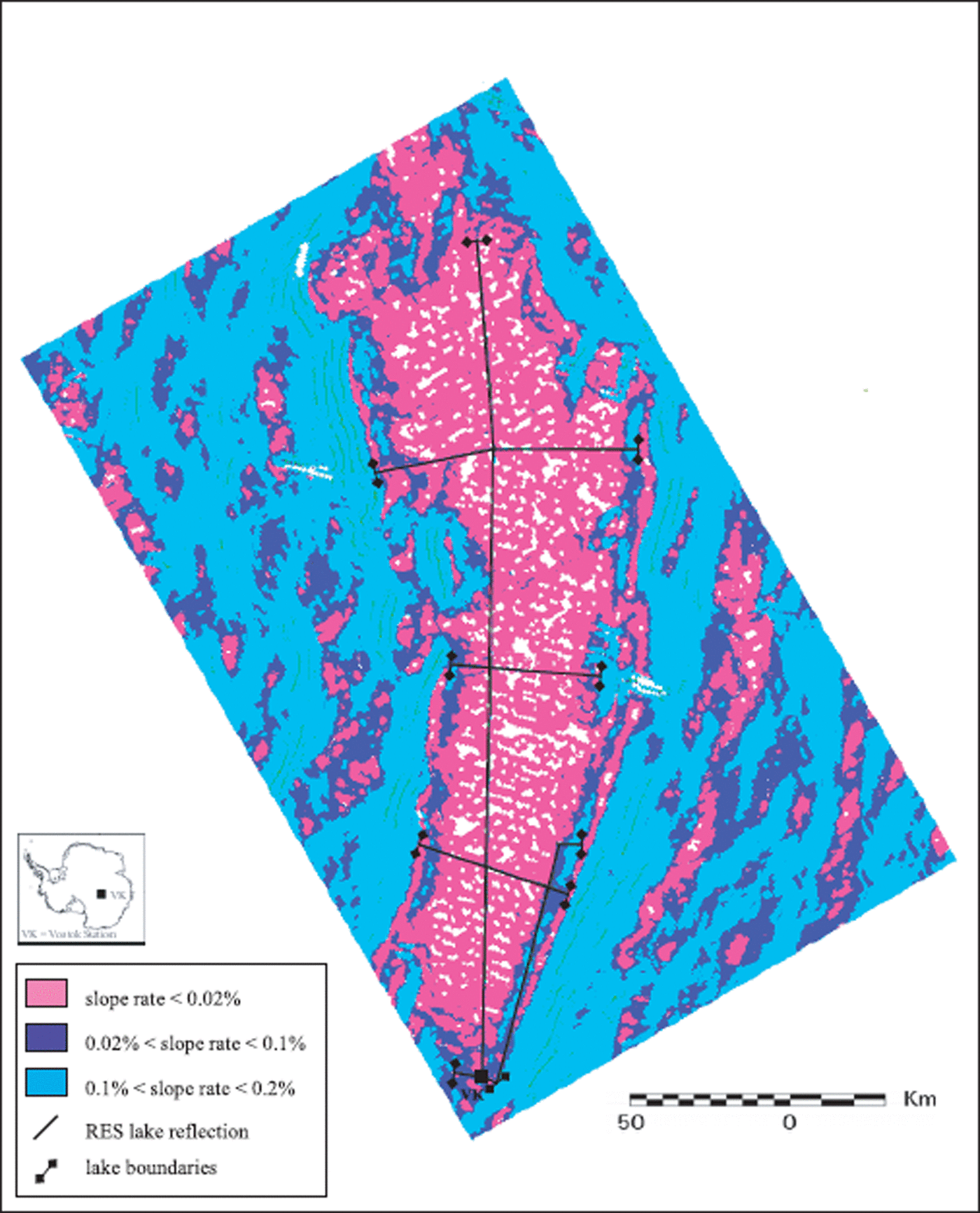
Fig. 8. Map of surface gradients superimposed on the tracks of radar reflections from the lake
Ice-surface and lake-ceiling ratios from south to north confirm the ice–water model in hydrostatic equilibrium.
Finally, we should point out that, along the western and eastern edges, lake-ceiling temperatures are higher and lower, respectively, than those over the central body of the lake. The east–west horizontal gradients on the pressure-dependent freezing temperature should be taken into account, in addition to the north–south gradient (e.g. Reference Wüest and CarmackWüest and Carmack, 2000), when modelling water circulation.
Acknowledgements
Research was carried out in the framework of the Project on Glaciology and Paleoclimatology of the Italian Programma Nazionale di Ricerche in Antartide. The work was made possible by logistical support from Ente per le Nuove Tecnologie, l’Energia e l’Ambiente; in particular we thank M. Zucchelli for his decisive contribution. We thank G. Orombelli and M. Frezzotti for their suggestions and R. A. Bindschadler (Scientific Editor), M.J. Siegert and the anonymous reviewer for their critical and useful observations.


