


1. Introduction
The interaction of water waves with impermeable vertical cylinders extending through the surface of a fluid has been an active area of study over many decades. This is partly because of its practical relevance in relation to marine structures such as the supporting columns of wind turbines, oil rigs, bridges and so on. In conjunction, the boundary-value problem that results from the mathematical description of the water–wave problem is amenable to analytic methods with particular advantage being taken of the alignment of fluid boundaries with coordinate surfaces in cylindrical polar coordinates. Consequently, it also acts as a prototype problem for many computational and experimental methods.
Under the small-amplitude (linearised) description of water waves, the scattering of incident plane waves by a single rigid vertical cylinder extending upwards through the surface from the bed of a fluid of constant depth is explicit; see MacCamy & Fuchs (Reference MacCamy and Fuchs1954). For cylinders extending uniformly through the depth, the dependence upon vertical coordinate is separable and, consequently, the problem is governed by the two-dimensional Helmholtz equation with the implication that the solutions have interpretations in other physical settings such as two-dimensional linearised acoustics and transverse-magnetic-polarised electromagnetics. The extension to multiple cylinders has been the subject of a number of papers (e.g. Siddorn & Eatock Taylor Reference Siddorn and Eatock Taylor2008; Zheng, Zhang & Iglesias Reference Zheng, Zhang and Iglesias2018) and the theory for a finite number of arbitrarily placed cylinders in a water wave setting is described by Linton & Evans (Reference Linton and Evans1990), who followed and extended the original method of solution devised by Záviška (Reference Záviška1913) and later Spring & Monkmeyer (Reference Spring and Monkmeyer1974) to show that the forces on the cylinders could be expressed in a particularly simple way in terms of the solution of certain infinite systems of equations. A number of interesting effects occur when waves interact with multiple vertical cylinders. For example, when then vertical axes of  $N\geq 4$ cylinders are equally spaced in a circular arrangement, Evans & Porter (Reference Evans and Porter1997) showed that large amplifications of the incident waves could occur inside the ring of cylinders. This so-called near-trapping phenomenon becomes especially dramatic as the gaps between cylinders become much smaller than the cylinder diameter, resulting in large peaks in wave forces close to certain frequencies linked to near resonance.
For long arrays of cylinders with vertical axes equally spaced along a straight line (a truncated periodic array) Maniar & Newman (Reference Maniar and Newman1997) also discovered a near-trapping phenomenon with similar consequences on surface elevation and cylinder wave force amplification. This time, the connection was made to free oscillations that were shown to occur in the equivalent infinite periodic array (e.g. Linton & Evans Reference Linton and Evans1993; Porter & Evans Reference Porter and Evans1999; Thompson, Linton & Porter Reference Thompson, Linton and Porter2008). Notable extensions to problems involving non-circular cylinders, truncated cylinders, second-order theory and ice covered surfaces are described by Chatjigeorgiou (Reference Chatjigeorgiou2011), Zheng et al. (Reference Zheng, Zhang, Liu and Iglesias2020b), Wolgamot, Eatock Taylor & Taylor (Reference Wolgamot, Eatock Taylor and Taylor2015), Malenica, Eatock Taylor & Huang (Reference Malenica, Eatock Taylor and Huang1999) and Ren, Wu & Ji (Reference Ren, Wu and Ji2018). It is worth remarking here that if the cylinder is not uniform in the depth (i.e. it is truncated), the boundary-value problem becomes more complicated as the separable depth dependence can no longer be assumed and solutions are complicated by the need to expand over an infinite set of depth eigenfunctions (e.g. Zheng, Zhang & Iglesias Reference Zheng, Zhang and Iglesias2019a; Zheng et al. Reference Zheng, Zhang, Liu and Iglesias2019b).
In this paper the focus is on vertical cylinders which are no longer rigid and impermeable, but which are structured in such a way that fluid is allowed to flow inside the cylinder. The particular structure of the cylinder we choose to consider is comprised of closely spaced thin parallel array of vertical plates whose lateral edges form the outline of a cylinder when viewed from above. Thus the fluid (and waves on the surface of the fluid) can move between the plates in the direction of the plates, but there is limited motion perpendicular to the plates owing to the assumed narrowness of the gaps between adjacent plates forming the structure. The idea for the use of such a structure in the water wave context originates from Porter (Reference Porter2018), who used the same parallel-plate-array ‘metamaterial’ occupying an infinitely long rectangular domain. The terminology metamaterial is used to describe a medium which exhibits behaviour not associated with normal materials; this is manifested by some complicated form of anisotropy. A metamaterial obtains its properties from a microstructure whose length scale is much smaller than that of the underlying field variables. Properties may be obtained by direct simulation, or by deriving an effective equation governing the microstructured medium via homogenisation or a multiscale method. See for example, Mei & Vernescu (Reference Mei and Vernescu2010), Berraquero et al. (Reference Berraquero, Maurel, Petitjeans and Pagneux2013) and Maurel et al. (Reference Maurel, Marigo, Cobelli, Petitjeans and Pagneux2017) for general theory and its application to structured bathymetry in water waves as devices for producing anisotropic effects in surface wave propagation. Porter (Reference Porter2018) shows that the plate-array metamaterial is governed by a reduced wave equation allowing waves to travel only in the direction aligned with the plate array. This anisotropy of wave propagation manifested itself both as an all-frequency perfectly transmitting negative refraction device for a particular incident wave angle or as a perfectly transmitting all-angle negative refraction device for particular frequencies. Also in Porter (Reference Porter2018) an outline description of the use of the metamaterial plate-array vertical cylinder was produced with some preliminary results. For example, for wave headings aligned with the plate array, the cylinder is transparent to incident waves whilst for other wave headings and frequencies the interaction is more complicated producing, in general, unsymmetric wave diffraction.
This paper develops the preliminary study of Porter (Reference Porter2018) on cylinders and extends the theory in two directions. First, we consider multiple cylinders and the interaction between them. Secondly, recognising that the assumed narrow fluid channels between the closely spaced plates may lead to viscous damping, we include in our model an artificial linear damping mechanism added to the free-surface dynamics. Although not directly related to the physical source of viscous damping on the vertical plate structures, artificial damping in the free-surface condition is a commonly used device whose dependence upon physical parameters, we imagine, can be parametrised via computational fluid dynamics or experimental methods. Whilst standard analytic tools (see above) can be used to consider the interaction between multiple cylinders, the addition of damping to the surface condition inside the metamaterial cylinder means we no longer enjoy a separable depth dependence and are required to deploy a full expansion in depth eigenfunctions for the velocity potential. The application of effective boundary conditions matching the flow in the exterior of the cylinders to the uni-directional flow inside the structured cylinders leads to infinite systems of equations to be solved. This procedure follows the problem statement outlined in § 2 of the paper where subsequently we derive (with algebraic details relegated to appendix B) expressions for the rate of energy dissipation due to damping and the far-field diffraction coefficient. In § 3 we describe the numerical convergence characteristics and validate the model. In § 4 we produce a set of results mainly focusing on the interaction effects between two cylinders. Particular attention is given to wave focusing, wave sheltering and energy dissipation characteristics. We draw conclusions to the work in § 5 systematically.
2. Mathematical model
In this model, a number ( $N$) of metamaterial circular cylinders conceptually deployed as an array in water of finite depth $h$ are considered (see figure 1). A global Cartesian coordinate system $Oxyz$ is chosen with the mean free surface coinciding with the $(x,y)$-plane and $z$ measured vertically upwards. Hence the fluid bottom is at $z=-h$. Cylinder $n$ with its radius denoted as $R_n$ is composed of a periodic array of infinitely thin vertical plates rotated through a clockwise angle $\beta _n$ relative to the $Ox$ axis; $(x_n,y_n,0)$ denotes the horizontal position of cylinder $n$ in the coordinate system $Oxyz$. Plane waves propagating at an angle $\beta$ relative to the $Ox$ axis are incident on these metamaterial cylinders. Fluid is allowed to flow in gaps between adjacent plates and waves are supported by the free surface. In addition to the global Cartesian coordinate system, the local one $O_nx'_ny'_n$ is also adopted with $O_nx'_n$ in parallel with the plates. The effect of these plates allows waves to propagate in the $\pm O_nx'_n$-direction only. Moreover, $N$ cylindrical coordinate systems, $O_nr_n\theta _nz$, are chosen for the purpose of convenience of mathematical expression. Additionally, one more cylindrical coordinate system $Or_0\theta _0z$ is defined (not plotted in figure 1), the origin of which coincides with the coordinate system $Oxyz$. $R_{n,j}$ and $\alpha _{n,j}$ denote the length and the angle, respectively, of a vector pointing from $O_n$ to $O_j$.

Figure 1. Schematic of an array of metamaterial cylinders:  $(a)$ global and local Cartesian coordinate systems; $(b)$ local cylindrical coordinate systems.
We assume that all amplitudes are small enough that linear theory applies and we make the usual assumptions that the fluid is inviscid, incompressible and its motion is irrotational. We denote the fluid velocity potential by  ${\varPhi }(x,y,z,t)$. It is further assumed that all motion is time harmonic with angular frequency $\omega$. Thus, we can write
 \begin{equation} {\varPhi}(x,y,z,t)=\mathrm{Re}\{\phi(x,y,z)\exp({-{\textrm{i}}\omega t})\}, \end{equation}
where  $\mathrm {Re}$ denotes the real part. Thus $\phi$ is the spatial velocity potential which is independent of time, i.e. $t$.
$t$.  ${{\textrm {i}}}$ is the imaginary unit.
The fluid domain can be divided into  $N$ interior domains, which fill the $N$ cylinders accordingly, and an exterior domain, representing the remainder of fluid domain extending towards infinity horizontally.
The spatial velocity potential satisfies Laplace equation,
 \begin{equation} {\triangledown^2}\phi=0 \quad \text{in the water}, \end{equation}
the boundary condition at sea bed,
 \begin{equation} \frac{\partial\phi}{\partial z}=0, \quad z=-h, \end{equation}
and the boundary condition at the water surface of the exterior domain
 \begin{equation} \frac{\partial\phi}{\partial z}=\frac{\omega^2}{g}\phi, \quad z=0, \end{equation}
in which  $g$ denotes the acceleration due to gravity.
Within the fluid in the  $n$th cylinder, (2.2) also holds although it is confined to narrow disconnected domains bounded by thin plates aligned with the $x_n'$ coordinate. Writing (2.2) in coordinates $O_n x_n' y_n'$ with rescaled in $x_n'$ and $y_n'$ coordinates and imposing the boundary conditions on the channel walls shows that the field within the whole of the $n$th cylinder is governed by an effective medium governing equation involving the reduced Laplacian
 \begin{equation} \left(\partial^2/\partial_{x_n'}^2 + \partial^2/\partial z^2\right) \phi = 0. \end{equation}
 It is assumed that the separation between plates is small compared to the wavelength (i.e.  $d_p/\lambda \ll 1$ where $d_p$ is the distance between plates and $\lambda$ is the wavelength) and also the length of the plate (i.e. $d_p/L_p \ll 1$ where $L_p$ is the length of the plate). See also Porter (Reference Porter2018) and Jan & Porter (Reference Jan and Porter2018) who employed the same models. Equation (2.5) represents conservation of mass for an irrotational flow in which the motion perpendicular to the plates is inhibited.
Within the boundary of the cylinder and between the plates we allow for the possibility of energy dissipation and will employ the modified free-surface condition
 \begin{equation} \frac{\partial\phi}{\partial z}=\frac{\omega^2\phi}{g(1-\bar{\nu}{\textrm{i}})} , \quad z=0, \end{equation}
(sometimes referred to as a ‘damping lid’ model, e.g. Kim, Koo & Hong Reference Kim, Koo and Hong2014; Dinoi Reference Dinoi2016) with  $\bar {\nu } \geq 0$ within the cylinder as a means of achieving this. We identify three physical settings in which this condition applies.
The first is that the surface of the fluid within the cylinder is covered with a fixed porous medium with permeability  $\kappa$ submerged to a small depth $d$. The flow through small vertical pores is assumed to be dominated by the fluid dynamic viscosity, $\mu$, and it is appropriate to use Darcy's law (e.g. Chwang & Chan Reference Chwang and Chan1998) to relate the vertical fluid velocity $w$ to the pressure gradient $p_z$ via $w = -(\kappa /\mu ) (p_z + \rho g )$, where $\rho$ represents the water density. Integrating subject to the kinematic and dynamic free-surface conditions and matching the pressure and the mass flux to an inviscid fluid described by potential flow theory beneath the porous medium readily leads to the free-surface condition
 \begin{equation} \frac{\partial \phi}{\partial z} = \frac{\alpha \omega^2 \phi}{g (1-{\textrm{i}}\omega \mu d/(\rho g\kappa))}, \quad z=0, \end{equation}
where  $0 < \alpha \leq 1$ is a ‘blockage coefficient’ representing the fractional area of the medium occupied by pores in horizontal cross-section.
The second physical setting involves the surface of the narrow channels within the cylinder being covered by floating buoys constrained to move in heave. The buoys are designed to operate as wave energy converters being connected to a power take-off mechanism with a linear damping rate  $c$. Garnaud & Mei (Reference Garnaud and Mei2009) showed, using multiscale homogenisation theory underpinned by an assumed contrast in wavelength and buoy separation, that the effect of a compact array of buoys occupying a fraction $\gamma \in (0,1]$ of the area of the surface can be represented by the modified free-surface condition
 \begin{equation} \frac{\partial\phi}{\partial z}=\frac{[1+{\textrm{i}}\omega(\gamma-1)c]\omega^2\phi}{g(1-{\textrm{i}}\omega c)}, \quad z=0, \end{equation}
which coincides with (2.6) when  $\gamma = 1$. Garnaud & Mei (Reference Garnaud and Mei2009) give an example of the application of this condition to an array of buoys along a rectangular channel.
The final setting arises from consideration of the viscous dissipation due to fluid interaction with the sidewalls and bottom of the narrow rectangular fluid-filled channels with a normal air–fluid free surface. Hunt (Reference Hunt1952) and Mei, Stiassnie & Yue (Reference Mei, Stiassnie and Yue2005) (§ 9, Exercise 9.2) have shown that the effect of dynamic viscosity,  $\mu$, on a plane wave of angular frequency $\omega$ propagating along a uniform channel of width $d_p$ and depth $h$ is to shift the inviscid wavenumber from $k$ to
 \begin{equation} k' = k( 1+ (1+{\textrm{i}}) \epsilon) \approx k (1+{\textrm{i}} \epsilon), \end{equation}
provided  $k$ is not close to zero and
 \begin{equation} \epsilon =\frac{\omega^2}{g}\sqrt{\frac{\mu}{\rho \omega}}\frac{\sqrt{2}k}{d_p}\left(\frac{k d_p+\sinh(2kh)}{2kh+\sinh(2kh)}\right) \end{equation}
is small. The condition (2.6) can be used to generate the same effect since, if  $\bar {\nu }$ is small, and the velocity potential of a propagating wave along the channel is sought to in the form $\exp ({{\textrm {i}} k' x}){\cosh [k'(z+h)]}/{\cosh (k'h)}$ satisfying (2.6) we find that
 \begin{equation} \frac{\omega^2}{g} (1 + {\textrm{i}} \bar{\nu}) = k' \tanh k'h, \end{equation}
implying
 \begin{equation} k' \approx k \left(1 + \frac{{\textrm{i}} \bar{\nu}}{1+2kh/\sinh (2 kh)}\right) \end{equation}
and allowing a connection to be made between  $\bar {\nu }$ and $\epsilon$ in (2.12) and (2.9) above.
The range of values of  $\bar {\nu }$ that we shall consider in later results may not be appropriate to all physical settings but are included to demonstrate the full range of wave interaction available under the condition (2.6).
2.1. Expressions of spatial velocity potential in different domains
The standard method of eigenfunction expansions is used to solve the wave–structure interaction problem (e.g. Mei Reference Mei1983).
2.1.1. Exterior domain
The spatial velocity potential in the exterior domain can be expressed as (e.g. Siddorn & Eatock Taylor Reference Siddorn and Eatock Taylor2008; Zheng & Zhang Reference Zheng and Zhang2018)
 \begin{equation} \phi_{ext}=\phi_I+\sum_{n=1}^N\sum_{m=-\infty}^{\infty}\sum_{l=0}^{\infty}A_{m,l}^{(n)}H_m(k_lr_n)Z_l(z) \exp({{{\textrm{i}}} m\theta _n}), \end{equation}
where  $\phi _I$ represents the velocity potential of incident waves. The second term denotes the components contributed by the waves scattered from the $N$ cylinders; $A_{m,l}^{(n)}$ are the unknown coefficients to be determined; $H_m$ denotes the Hankel function of the first kind of order $m$;
$m$;  $Z_l(z)={\cosh [k_l(z+h)]}/{\cosh (k_lh)}$; $k_0\in \mathbb {R}^+$ and $k_l\in \mathrm {i}\mathbb {R}^+$ for $l=1, 2, 3, \ldots$ are associated with propagating waves and evanescent waves, respectively, and they are the positive real root and the infinite positive imaginary roots of the dispersion relation for the exterior domain
 \begin{equation} \omega^2=gk_l\tanh(k_lh). \end{equation}
 For the plane incident waves with amplitude  $A$, angular frequency $\omega$ and wave direction $\beta$, $\phi _I$ can be expressed in the coordinate systems of $Oxyz$ and $O_nr_n\theta _nz$, respectively, as
 \begin{equation} \phi_I(x,y,z)=-\frac{{{\textrm{i}}}gA}{\omega}\exp({{{\textrm{i}}}k_0(x\cos\beta+y\sin\beta)})Z_0(z), \end{equation}
and
 \begin{align} \phi_I(r_n,\theta_n,z)&=-\frac{{{\textrm{i}}}gA}{\omega}\exp({{{\textrm{i}}}k_0(x_n\cos\beta+y_n\sin\beta)})Z_0(z)\nonumber\\ &\qquad \times \sum_{m=-\infty}^{\infty}{{\textrm{i}}}^m \exp({-{{\textrm{i}}}m\beta})\text{J}_m(k_0r_n)\exp({{{\textrm{i}}}m\theta_n}), \end{align}
where  $\text{J}_m$ is the Bessel function of order $m$ (e.g. Linton & Evans Reference Linton and Evans1990; Zheng & Zhang Reference Zheng and Zhang2018).
After using Graf's addition theorem for Bessel functions,  $\phi _{ext}$ can be rewritten in the cylindrical coordinate system $O_n r_n \theta _n$ as
 \begin{align} &\phi_{ext}(r_n,\theta_n,z)=\phi_{I}+\sum_{m=-\infty}^{\infty}\sum_{l=0}^{\infty}A_{m,l}^{(n)}H_m(k_lr_n)Z_l(z)\exp({\mathrm{i}m\theta_n})\nonumber\\ &\quad +\sum_{\substack{j=1,\\ {j{\neq}{n}}}}^{N}\sum_{m=-\infty}^{\infty}\sum_{l=0}^{\infty} A_{m,l}^{(j)}Z_l(z)\sum_{m^{\prime}=-\infty}^{\infty}(-1)^{m^{\prime}}H_{m-m^{\prime}}(k_lR_{n,j})J_{m^{\prime}}(k_lr_n) \exp(\mathrm{i}(m\alpha_{j,n}\nonumber\\ &\qquad -m^{\prime}\alpha_{n,j}))\exp({\mathrm{i}m^{\prime}\theta_n})\quad \text{for} \ r_n<\min_{\substack{j=1, N;\\ {j{\neq}{n}}}}R_{n,j}. \end{align}
2.1.2. Interior domain
General solutions of the reduced Laplace's equation, i.e. (2.5), inside the  $n$th cylinder satisfying free-surface and bed boundary conditions, i.e. (2.6) and (2.4), can be expressed as
 \begin{align} &\phi_{int}^{(n)}(x'_n,y'_n,z)=\sum_{l=0}^{\infty}Y_l(z)\left[B_{n,l}(y'_n)\exp({{{\textrm{i}}}k'_lx'_n})+C_{n,l}(y'_n) \exp({-{{\textrm{i}}}k'_lx'_n})\right]\nonumber\\ &\quad =\sum_{l=0}^{\infty}Y_l(z)\left[E_{n,l}(\theta'_n)\exp({{{\textrm{i}}}k'_lr_n\cos(\theta_n-\beta_n)})+F_{n,l}(\theta'_n) \exp({-{{\textrm{i}}}k'_lr_n\cos(\theta_n-\beta_n)})\right], \end{align}
where  $Y_l(z)={\cosh [k'_l(z+h)]}/{\cosh (k'_lh)}$; $k'_l$ for $l=0, 1, 2, 3, \ldots$ are the complex roots of the dispersion relation for the interior domains
 \begin{equation} k'_l\tanh(k'_lh)=\frac{\omega^2}{g(1-\bar{\nu}{\textrm{i}})}, \end{equation}
which degenerates into the dispersion relation for the exterior domain, i.e. (2.14), when  $\bar {\nu }=0$. The values of $k'_l$ for $l=0, 1, 2, 3, \ldots$ can be calculated using an analytic continuation method, starting with the corresponding roots for the case of $\bar {\nu }=0$ (i.e. $k_l$ for $l=0, 1, 2, 3, \ldots$), and incrementing $\bar {\nu }$ to the specified value (e.g. Meylan, Bennetts & Peter Reference Meylan, Bennetts and Peter2017; Zheng et al. Reference Zheng, Meylan, Fan, Greaves and Iglesias2020a).
In (2.18),  $B_{n,l}$ and $C_{n,l}$ are coefficients expressing the amplitude of waves propagating in each direction within the channels as a function of $y'_n$; $E_{n,l}$ and $F_{n,l}$ are the same coefficients as a function of the angle ( $\theta '_n$) at which the channel emerges at the edge of the cylinder (i.e. the angle of $\overrightarrow {O_nP'}$ as shown in figure 2).

Figure 2. Schematic definition of  $\theta '_n$.
When  $r_n=R_n$, we have $\theta '_n=\theta _n$, and
 \begin{equation} E_{n,l}(\theta_n)=E_{n,l}({\rm \pi}+2\beta_n-\theta_n), \quad F_{n,l}(\theta_n)=F_{n,l}({\rm \pi}+2\beta_n-\theta_n), \end{equation}
which express the fact that the channels between the plates connect the cylindrical surface  $\theta _n\in [\beta _n-{\rm \pi} /2,\beta _n+{\rm \pi} /2]$ and $\theta _n\in [\beta _n+{\rm \pi} /2,\beta _n+3{\rm \pi} /2]$.
With consideration of the properties as given in (2.20a,b), and for the purposes of deriving a solution, we expand the functions  $E_{n,l}$ and $F_{n,l}$ as
 \begin{align} E_{n,l}(\theta_n)=\sum_{p=0}^{\infty}E_{p,l}^{(n)}\cos \left[p\left(\theta_n-\beta_n-\frac{\rm \pi}{2}\right)\right],\quad F_{n,l}(\theta_n)=\sum_{p=0}^{\infty}F_{p,l}^{(n)} \cos\left[p\left(\theta_n-\beta_n-\frac{\rm \pi}{2}\right)\right], \end{align}
where  $E_{p,l}^{(n)}$ and $F_{p,l}^{(n)}$ are the unknown coefficients to be determined.
The expression of  $\phi _{int}^{(n)}$ as given in (2.18) can be further rewritten with the employment of
 \begin{equation} \exp({{{\textrm{i}}}k'_lr_n\cos(\theta_n-\beta_n)})=\sum_{m=-\infty}^{\infty}{{\textrm{i}}}^m\text{J}_m(k'_lr_n) \exp({{{\textrm{i}}}m(\theta_n-\beta_n)}), \end{equation}
and
 \begin{equation} \exp({-{{\textrm{i}}}k'_lr_n\cos(\theta_n-\beta_n)})=\sum_{m=-\infty}^{\infty}(-{{\textrm{i}}})^m\text{J}_m(k'_lr_n) \exp({{{\textrm{i}}}m(\theta_n-\beta_n)}). \end{equation}
2.2. Solution of unknown coefficients
Continuity of the field in terms of pressure and flux across the interfaces of the interior and exterior domains requires
 \begin{gather} \phi_{int}^{(n)}=\phi_{ext}, \quad \text{for} \ r_n=R_n, \end{gather}
 \begin{gather} \frac{\partial \phi_{int}^{(n)}}{\partial x'_n}\cos(\theta_n-\beta_n)=\frac{\partial \phi_{ext}}{\partial r_n}, \quad \text{for} \ r_n=R_n, \end{gather}
which can be used to determine the unknown coefficients  $A_{m,l}^{(n)}$, $E_{p,l}^{(n)}$ and $F_{p,l}^{(n)}$. The latter condition is derived from a flux balance through a small right-angled triangle with sides approximating the circular boundary of the cylinder, the perpendicular line across the entrance to a narrow channel and a channel sidewall. Detail derivation and calculation of the unknown coefficients are given in appendix A.
2.3. Wave motion, far-field scattering amplitudes and wave power dissipation
2.3.1. Wave motion
The water elevation non-dimensionalised by the incident wave amplitude can be expressed as
 \begin{equation} \bar{\eta}=\frac{1}{A}\textrm{Re}\left[\left.\frac{{{\textrm{i}}}\omega}{g(1-\bar{\nu}{\textrm{i}})}\phi\right|_{z=0} \exp({-{{\textrm{i}}}\omega t})\right], \end{equation}
in which the term  $-\bar {\nu }{\textrm {i}}$ will vanish for the exterior domain.
2.3.2. Far-field scattering amplitudes
In the water domain far away from an array of metamaterial cylinders, only the propagating modes exist in the scattered waves. With the asymptotic forms of  $H_m$ for $r_0\rightarrow \infty$,
 \begin{equation} H_m(kr_0)=\sqrt{2/{\rm \pi}}\exp({-\mathrm{i}(m{\rm \pi}/2+{\rm \pi}/4)})(kr_0)^{-1/2}\exp({\mathrm{i}kr_0}) \quad \text{for}\ r_0\rightarrow \infty, \end{equation}
the scattered wave potential, i.e. the accumulative term in (2.13), can be rewritten as
 \begin{align} \phi_{S}&=\phi-\phi_I=\sqrt{2/{\rm \pi}}Z_0(z)\sum_{n=1}^N\sum_{m=-\infty}^{\infty} A_{m,0}^{(n)}\exp({-\mathrm{i}(m{\rm \pi}/2+{\rm \pi}/4)})(kr_n)^{-1/2}\nonumber\\ &\quad \times \exp({\mathrm{i}kr_n})\exp({\mathrm{i}m\theta_n}), \quad r_0\rightarrow \infty, \end{align}
which can be further expressed in the global cylindrical coordinate system  $O_0r_0\theta _0z$ as
 \begin{align} \phi_{S}&=\sqrt{2/{\rm \pi}}(kr_0)^{-1/2}\exp({\mathrm{i}kr_0})Z_0(z)\sum_{n=1}^N\sum_{m=-\infty}^{\infty} A_{m,0}^{(n)}\exp({-\mathrm{i}kR_{0,n}\cos(\alpha_{0,n}-\theta_0)}) \nonumber\\ &\quad \times \exp({-\mathrm{i}(m{\rm \pi}/2+{\rm \pi}/4)}) \exp({\mathrm{i}m\theta_0})\nonumber\\ &=A_S(\theta_0)\frac{g}{{\textrm{i}} \omega}\sqrt{2{\rm \pi}}(kr_0)^{-1/2} \exp({\mathrm{i}(kr_0-{\rm \pi}/4)})Z_0(z),\qquad r_0\rightarrow \infty, \end{align}
where  $A_S$ is the so-called far-field scattering amplitude that is independent of $r_0$ and $z$, and can be expressed as
 \begin{equation} A_S(\theta_0)=\frac{{\textrm{i}}\omega}{g{\rm \pi}}\sum_{n=1}^N\sum_{m=-\infty}^{\infty} A_{m,0}^{(n)} \exp({-\mathrm{i}kR_{0,n}\cos(\alpha_{0,n}-\theta_0)})\exp({\mathrm{i}m(\theta_0-{\rm \pi}/2)}). \end{equation}
2.3.3. Wave power dissipation
The energy dissipated by the  $N$ metamaterial cylinders due to damping coefficient can be calculated by (Zheng et al. Reference Zheng, Meylan, Fan, Greaves and Iglesias2020a)
 \begin{equation} P_{diss}=\frac{\rho g \omega \bar{\nu}}{2}\sum_{n=1}^{N}\iint_{\varOmega_n}|\eta|^2\,\textrm{d}s =\frac{\rho\omega^3 \bar{\nu}}{2 g(1+\bar{\nu}^2)}\sum_{n=1}^{N}\iint_{\varOmega_n}|\phi|^2\,\textrm{d}s, \end{equation}
where  $\varOmega _n$ denotes the water surface of the interior domain occupied by cylinder $n$, and $\eta$ denotes the time-independent surface elevation.
Equation (2.3) presents a straightforward way to calculate the energy dissipation by the array of metamaterial cylinders. From the view of energy identities, the energy dissipation can also be evaluated based on the spatial potentials in the exterior domain
 \begin{equation} P_{diss}=\frac{\rho\omega}{4\mathrm{i}}\iint_{\varOmega_R}\left(\phi\frac{\partial\phi^*}{\partial r_0}-\phi^*\frac{\partial\phi}{\partial r_0}\right)\textrm{d}s, \end{equation}
where  $\varOmega _R$ represents an envisaged vertical cylindrical control surface with its radius denoted by $r_0=R_0$, which is large enough to enclose all the cylinders. The derivation process of (2.32) can be found in appendix B; when $r_0=R_0\rightarrow \infty$, (2.32) holds as well with the control surface $\varOmega _R$ replaced by $\varOmega _{\infty }$, i.e. $r_0\rightarrow \infty$.
It has been shown that the integral in (2.32) can be expressed in terms of Kochin functions (Falnes Reference Falnes2002),
 \begin{align} \iint_{\varOmega_{\infty}}\left(\phi\frac{\partial\phi^*}{\partial r_0}-\phi^*\frac{\partial\phi}{\partial r_0}\right)\textrm{d}s=\frac{2\mathrm{i}AgD(k_0h)}{\omega k}\mathrm{Re}[H_R(\beta)]-\frac{\mathrm{i}D(k_0h)}{2{\rm \pi} k}\int_0^{2{\rm \pi}}|H_R(\theta_0)|^2\,\textrm{d}\theta_0, \end{align}
where
 \begin{equation} D(k_0h)=\left[1+\frac{2k_0h}{\sinh(2k_0h)}\right]\tanh(k_0h), \end{equation}
where  $H_R$ is the Kochin function which can be expressed as follows (Falnes Reference Falnes2002)
 \begin{equation} H_R(\theta_0)=2\sum_{n=1}^N\sum_{m=-\infty}^{\infty} A_{m,0}^{(n)} \exp({-\mathrm{i}k_0R_{0,n}\cos(\alpha_{0,n}-\theta_0)})(-\mathrm{i})^{m+1} \exp({\mathrm{i}m\theta_0}). \end{equation}
Therefore, the energy dissipated by the array of metamaterial cylinders can be evaluated by using an indirect method based on Kochin functions
 \begin{equation} P_{{diss}}=\frac{\rho\omega D(k_0h)}{k_0}\left(\frac{Ag}{2\omega}\mathrm{Re}[H_R(\beta)]-\frac{1}{8{\rm \pi}}\int_0^{2{\rm \pi}}|H_R(\theta_0)|^2\,\textrm{d}\theta_0\right), \end{equation}
which presents a way to check the accuracy of the proposed semi-analytical model.
The energy dissipated by the cylinders can be written in non-dimensional format as
 \begin{equation} \eta_{diss}=\frac{k P_{diss}}{P_{in}}, \end{equation}
where  $P_{in}$ is the incident wave power per unit width of wave front,
 \begin{equation} P_{in}=\frac{\rho g A^2}{2}\frac{\omega}{2k}\left[1+\frac{2kh}{\sinh(2kh)}\right]. \end{equation}
3. Model validation
The effect of truncation of the infinite sums on the angular and vertical modes to finite sums over  $-M \leq m \leq M$ and $0 \leq l \leq L$ have been carried out and suggest that $M \geq 20$ and $L \geq 5$ provide sufficiently converged results for $kh=1.3$. As $kh$ becomes larger, more truncated terms of $m$ and $l$ may be required to obtain the converged results. Hereinafter, $M = 20$ and $L = 5$ are adopted unless otherwise specified.
For  $\bar {\nu }=0$ with $\beta _n=\beta$, i.e. when waves propagate into the cylinders with the plates aligned to the incident wave direction, the incident waves would not be affected at all. figure 3 presents the predicted wave field around a pair of metamaterial cylinders with $R_1/h=R_2/h=1.0$, $-x_1/h=x_2/h=2.0$, $\beta _n=\beta ={\rm \pi} /4$, $\bar {\nu }=0$.

Figure 3. Instantaneous wave field due to incident wave propagation with  $kh=1.3$, $\beta ={\rm \pi} /4$ on a pair of metamaterial cylinders with $R_1/h=R_2/h=1.0$, $-x_1/h=x_2/h=2.0$, $y_1=y_2=0$, $\beta _n={\rm \pi} /4$, $\bar {\nu }=0$.
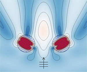
When the metamaterial cylinders are deployed far away from each other, the wave motion at each cylinder is expected to be the same as that for an isolated single metamaterial cylinder. Figure 4 illustrates the instantaneous wave field around one of a pair of metamaterial cylinders far apart from one another. The present results are found to agree well with those for a single metamaterial cylinder in the absence of damping as investigated by Porter (Reference Porter2018). Due to the effect of the closely spaced array of thin vertical plates aligned with the  $y$-axis, the scattering pattern outside the cylinder has broken the symmetry of the incident wave and is very different from that for a solid cylinder. Note that in figures 4(a) and 4(b), the cylinder redirects a ‘beam’ of energy rightward (i.e. in a direction perpendicular to the plate direction), which may be called a ‘beaming’ or ‘lensing’ effect, and it will be further investigated in § 4. Whilst the motion of the fluid in each channel appears to be separate from the next, there is coupling between channels on the boundary of the cylinder and this coupling seems to give rise to a slow wave with high energy propagating through the cylinder. Also, it is observed that the plates have the effect of inducing resonant-like behaviour in the fluid channels. This is particularly noticeable in figure 4(c) with $kh=1.6$, where there is a large resonant amplification in the channels whose lengths are approximately half a wavelength.

Figure 4. Instantaneous wave field in terms of  $\bar {\eta }$ at $t=0$ due to incident wave propagation with $\beta ={\rm \pi} /4$ on a pair of metamaterial cylinders with $R_1/h=R_2/h=1.0$, $x_1/h=0$, $x_2/h=200$, $y_1=y_2=0$, $\beta _1=\beta _2={\rm \pi} /2$, $\bar {\nu }=0$: $(a)$
$(a)$ $kh=1.0$, $(b)$
$(b)$ $kh=1.3$, $(c)$
$(c)$ $kh=1.6$. (Only the wave field at cylinder 1 is plotted; $M=50$ is adopted for $kh=1.6$.)
Another extreme case is that when  $\bar {\nu }\rightarrow \infty$, the wave motion on the surface of the internal region is strictly restricted, and the wave scattering problem becomes the same for the metamaterial cylinder with a fixed solid lid at the mean water surface, the wave scattering solution of which is derived in appendix C. Comparison of the wave field for a pair of metamaterial cylinders with $\bar {\nu }=10^5$ and that of metamaterial cylinders with fixed solid lids at the mean water level is plotted in figure 5. Note that a metamaterial cylinder with a rigid lid is not the same as a vertical cylinder with a rigid cylindrical surface. In the former case, fluid is still able to flow through the cylinder.

Figure 5. Instantaneous wave field due to incident wave propagation with  $kh=1.3$, $\beta ={\rm \pi} /4$ on a pair of metamaterial cylinders with $R_1/h=R_2/h=1.0$, $-x_1/h=x_2/h=2.0$, $y_1=y_2=0$, $\beta _1=\beta _2={\rm \pi} /2$: $(a)$ cylinders with a large damping coefficient, $\bar {\nu }=10^5$; $(b)$ cylinders with fixed solid lid at the mean water surface.
Additionally, the wave power dissipated by the metamaterial cylinders evaluated by using the direct method ((2.3)) and the indirect method ((2.36)) are presented in figure 6.

Figure 6. Wave power dissipation of a pair of metamaterial cylinders with  $R_1/h=R_2/h=1.0$, $-x_1/h=x_2/h=2.0$, $y_1=y_2=0$, $\beta _1=\beta _2={\rm \pi} /2$, $kh=1.3$ evaluated by using direct method (lines) and indirect method (symbols): $(a)$ variation of $\eta _{{diss}}$ with $\bar {\nu }$ for $\beta ={\rm \pi} /4$; $(b)$ variation of $\eta _{{diss}}$ with $\beta$ for $\bar {\nu }=0.1$.
Moreover, potential flow theory based numerical simulations are carried out with the employment of a commercial boundary element method (BEM) code AQWA (ANSYS, Inc. 2011) to study wave interaction with a metamaterial circular cylinder consisting of 20 thin vertical plates (figure 7). The thickness of each plate is  $0.02h$ and the spacing distance between the centres of adjacent plates is $0.1h$. The good agreement between the semi-analytical results (figure 4a) with BEM numerical simulations (figure 7b) confirms that the homogenisation of the structured cylinder into an effective medium with effective boundary conditions is a good approximation. An obvious advantage of the semi-analytical model lies in its high computational efficiency, and, indeed, our results are much easier to compute compared to BEM numerical computations.

Figure 7. Numerical simulation of wave interaction with a metamaterial circular cylinder consisting of 20 thin vertical plates,  $R_1/h = 1.0$, $x_1= y_1 = 0$, $\beta _1 = {\rm \pi}/2$, $\bar {\nu } = 0$: $(a)$ computational mesh with the wetted surface marked in blue colour; $(b)$ instantaneous wave field in terms of $\bar {\eta }$ at $t = 0$ due to incident wave propagation with $\beta = {\rm \pi}/4$, $kh=1.0$.
The excellent agreement between the results shown in figures 4–7, together with figure 3, gives confidence in the present model for solving wave scattering and predicting wave dissipation by an array of circular metamaterial cylinders.
4. Results and discussion
In this section, the effect of the metamaterial cylinders on wave focusing/blocking and scattered far-field amplitude is investigated with the employment of the validated semi-analytical model. Additionally, wave power dissipation of the cylinders is studied, and shows to form the foundation of a wave energy device with a high ‘capture width’ if the artificial surface damping used in our present model were to be replaced by a mechanical energy conversion device with similar effects.
Prior to investigating performance of a pair of metamaterial cylinders, the angle responses of the scattered far-field amplitude for a single metamaterial cylinder placed at  $x=y=0$ with $\beta _1=0$, ${\rm \pi} /6$, ${\rm \pi} /4$, ${\rm \pi} /3$, ${\rm \pi} /2$ are plotted in figure 8. For the non-damping situation as shown in figure 8(a), the main peak value of the far-field scattering wave amplitude and the corresponding angle are ( $|A_{S}|/A$, $\theta _0)=(1.75, 0.50{\rm \pi} )$, $(1.21, 0.67{\rm \pi} )$, $(0.73, 0.76{\rm \pi} )$ and $(0.34, 0.85{\rm \pi} )$ for $\beta _1=0$, ${\rm \pi} /6$, ${\rm \pi} /4$ and ${\rm \pi} /3$, respectively, in which $(\theta _0-\beta _1)\approx 0.5{\rm \pi}$ is satisfied, and moreover, the $|A_{S}|/A$ is vanishing at $\theta _0\pm 0.5{\rm \pi}$ approximately. This means the cylinder bends or redirects a ‘beam’ of energy in a direction perpendicular to the plate direction, though there is a loss in the intensity of this beam as the angle is rotated with respect to the incident wave angle. We note that there is very little lateral scattering of wave energy either laterally or back towards the incoming wave direction. That is, the metamaterial cylinder acts rather like a transparent lens, but also one which appears to absorb wave energy laterally into the microstructure and produce and intense forward beam. The same thing still roughly happens for $\bar {\nu }=0.1$ (figure 8b). However, when the damping is too large that it works like a solid lid placed on the surface of the structured cylinder (figure 8c), the angle response of the scattered far-field amplitude is lightly dependent on $\beta _1$, indicating that the orientation of the plates is relatively unimportant as far as the overall effect of the cylinder is on wave diffraction.

Figure 8. Far-field scattering wave amplitude due to incident wave propagation with  $kh=1.3$, $\beta ={\rm \pi} /2$ on a single metamaterial cylinder with $R_1/h=1.0$, $x_1=y_1=0$: $(a)$
$(a)$ $\bar {\nu }=0$; $(b)$
$(b)$ $\bar {\nu }=0.1$; $(c)$
$(c)$ $\bar {\nu }=10^5$.
4.1. Wave focusing/blocking
Figure 9 presents the near-field wave motion due to incident wave propagation with  $kh=1.3$, $\beta ={\rm \pi} /2$ on a pair of metamaterial cylinders deployed along the $x$ axis with $\bar {\nu }=0$. The two metamaterial cylinders have identical radius $R_1/h=R_2/h=1.0$, whereas the thin plates that comprise the two cylinders are opposite to each other, i.e. $\beta _2=-\beta _1$. Four cases with $\beta _1=0, -{\rm \pi} /6, {\rm \pi}/6$ and ${\rm \pi} /2$ are examined.

Figure 9. Wave motion due to incident wave propagation with  $kh=1.3$, $\beta ={\rm \pi} /2$ on a pair of metamaterial cylinders with $R_1/h=R_2/h=1.0$, $-x_1/h=x_2/h=2.0$, $y_1=y_2=0$, $\beta _2=-\beta _1$, $\bar {\nu }=0$: (a,e) $\beta _1=0$; (b,f) $\beta _1=-{\rm \pi} /6$; (c,g) $\beta _1={\rm \pi} /6$; (d,h) $\beta _1={\rm \pi} /2$. ((a–d) Wave amplitude and (e–h) instantaneous wave field at $t=0$.)
When  $\beta _1={\rm \pi} /2$, the waves pass through the cylinders with no scattering (figures 9d and 9h). For other values of $\beta _1$ the metamaterial cylinders interacts with incident waves in a non-trivial way. Compared to the waveward surface elevation, wave motion at the leeward region and close to the cylinders is more affected by the two cylinders. When the thin plates are all aligned along the incident wave crest line ( $\beta _1=0$, figures 9a and 9e), wave motion is suppressed at the region between the two cylinders, where two small areas of $\bar {\eta }<0.4$ are observed. Moreover, two larger wave attenuation areas of $\bar {\eta }<0.4$ can be found on the flanks of the pair of cylinders on the leeward side. On the other hand, wave motion is strengthened at the central leeward region, which extends to the two cylinders, forming an inverted ‘Y’ shape area of $\bar {\eta }>1.2$. For the case with $\beta _1=-{\rm \pi} /6$ (figures 9b and 9f), there is a wave focusing area at the central leeward region of the array as well, while the region is closer to the array, and the wave in the region is much more focused with $\bar {\eta }>2.0$. The largest wave amplitude in the computed range of the exterior region is $\bar {\eta }=2.31$, which occurs at $(x/h,\,y/h)=(0, 1.44)$. Meanwhile, there is a small narrow region of $\bar {\eta }<0.4$ observed immediately beyond each cylinder, where the smallest wave motion is $\bar {\eta }=0.02$ at $(x/h, y/h)=(\pm 1.86, 1.20)$. As a comparison, for the metamaterial cylinders with $\beta _1={\rm \pi} /6$ as shown in figures 9(c) and 9(g), there is a much larger area of $\bar {\eta }<0.4$ at the very leeward of the array, where waves are effectively blocked by the cylinders. At $(x/h, y/h)=(\pm 3.34, 4.86)$, $\bar {\eta }=0$ is obtained, meaning the incident wave can be completely blocked at specified points. The dramatic amplification and focusing effects on wave motion inside the metamaterial cylinders are observed for all the studied cases, except where $\beta _1={\rm \pi} /2$. The results as given in figure 9 demonstrates that wave focusing/blocking can be achieved by a pair of metamaterial cylinders with the appropriate control to the plates alignment direction.
The near-field wave motion due to the same incident waves propagating on the same metamaterial cylinders with  $\bar {\nu }=0.1$ is presented in figure 10. Due to wave power dissipation of the metamaterial cylinders, the wave focusing area ( $\bar {\eta }>1.2$) at the leeward region of the cylinders with $\beta _1=0$ (figures 9a and 9e) now mostly becomes a blocking region with $\bar {\eta }<0.8$ (figures 10a and 10e). What is more, the previous regions of $\bar {\eta }<0.4$ now merge together, resulting in a much larger ‘M’ shaped region. For the case with $\beta _1=-{\rm \pi} /6$ (figures 10b and 10f), as $\bar {\nu }$ increases from 0 to 0.1, the wave focusing region of $\bar {\eta }>1.2$ previously located at the central leeward of the array now moves to the gap between the cylinders, and gets smaller. Whereas the wave blocking regions of $\bar {\eta }<0.4$ grow and, as a result, they merge together into an inverted ‘V’ shape area. With the increase of $\bar {\nu }$ from 0 to 0.1, the wave blocking region of $\bar {\eta }<0.4$ for $\beta _1={\rm \pi} /6$ breaks into two regions, and the corresponding $\bar {\eta }<0.8$ region becomes broader (figures 10c and 10g). The previous amplification and focusing effects on wave motion inside the metamaterial cylinders are now significantly weakened by the damping, except the one with $\beta _1={\rm \pi} /2$. Due to the existence of damping, the incident wave is disturbed by the metamaterial cylinders with $\beta _1={\rm \pi} /2$, despite very limited influence (figures 10d and 10h).

Figure 10. Wave motion due to incident wave propagation with  $kh=1.3$, $\beta ={\rm \pi} /2$ on a pair of metamaterial cylinders with $R_1/h=R_2/h=1.0$, $-x_1/h=x_2/h=2.0$, $y_1=y_2=0$, $\beta _2=-\beta _1$, $\bar {\nu }=0.1$: (a,e) $\beta _1=0$; (b,f) $\beta _1=-{\rm \pi} /6$; (c,g) $\beta _1={\rm \pi} /6$; (d,h) $\beta _1={\rm \pi} /2$. ((a–d) Wave amplitude and (e–h) instantaneous wave field at $t=0$.)
Figure 11 illustrates the near-field wave motion when an extremely large damping  $\bar {\nu }=10^5$ is employed, which is equivalent to a solid lid placed on the surface of each cylinder. When a solid lid is put on the surface, it largely produces the same overall wave pattern. That is, the orientation the plates are relatively unimportant as far as the overall effect of the cylinder is on wave diffraction, which is in accordance with that obtained for the isolated cylinder (see figure 8c). The regions of $\bar {\eta }>1.2$ are distributed at the left and right sides of the array, and in the gap between the two cylinders. Additionally, due to wave reflection from the array, a region of $\bar {\eta }>1.2$ is observed at the waveward side as well, together with adjacent weakened region of $\bar {\eta }<0.8$.

Figure 11. Wave motion due to incident wave propagation with  $kh=1.3$, $\beta ={\rm \pi} /2$ on a pair of metamaterial cylinders with $R_1/h=R_2/h=1.0$, $-x_1/h=x_2/h=2.0$, $y_1=y_2=0$, $\beta _2=-\beta _1$, $\bar {\nu }=10^5$: (a,e) $\beta _1=0$; (b,f) $\beta _1=-{\rm \pi} /6$; (c,g) $\beta _1={\rm \pi} /6$; (d,h) $\beta _1={\rm \pi} /2$. ((a–d) Wave amplitude and (e–h) instantaneous wave field at $t=0$.)
4.2. Scattered far-field amplitude
Figure 12 shows the modulus of the scattered far-field amplitude for a pair of metamaterial cylinders with  $\beta _1=0,\,-{\rm \pi} /6,\,{\rm \pi} /6,\,{\rm \pi} /2$, and damping $\bar {\nu }=0,\,0.1,\,10^5$, in response to a plane incident wave at angle $\beta ={\rm \pi} /2$. Because of the symmetry of the pair of metamaterial cylinders, the $|A_{S}|/A$– $\theta _0$ curve is symmetrical approximately $\theta _0=0.5{\rm \pi}$ and $1.5{\rm \pi}$. For the metamaterial cylinders without any damping (figure 12a), since incident waves pass through the cylinders of $\beta _1={\rm \pi} /2$ with no scattering, the corresponding scattered far-field amplitude is vanishing. For the case of $\beta _1=0$, a very sharp peak of $|A_{S}|/A$ is obtained at $\theta _0=0.5{\rm \pi}$ with the peak value $|A_{S}|/A=3.40$. The $|A_{S}|/A$– $\theta _0$ curves of $\beta _1={\pm }{\rm \pi} /6$ almost overlap each other, and the main peak values of $|A_{S}|/A$ are both 1.52, occurring at $\theta _0=0.5{\rm \pi}$. In the range of $\theta _0\in [{\rm \pi} ,\,2.0{\rm \pi} ]$, $|A_{S}|/A$ is small regardless of the value of $\beta _1$. As $\bar {\nu }$ increases from 0 to 0.1 and $10^5$ (figures 12b and 12c), the main peaks at $\theta _0=0.5{\rm \pi}$ for $\beta _1=0$ and ${\pm }{\rm \pi} /6$ decline, whereas the $|A_{S}|/A$– $\theta _0$ curve for $\beta _1={\rm \pi} /2$ rises at $\theta _0=0.5{\rm \pi}$. Meanwhile, the $|A_{S}|/A$ response in the range of $\theta _0\in [{\rm \pi} , 2.0{\rm \pi} ]$ gets stronger and stronger, and the peaks occurring in this range ultimately become as large as those around $\theta _0=0.5{\rm \pi}$.

Figure 12. Far-field scattering wave amplitude due to incident wave propagation with  $kh=1.3$, $\beta ={\rm \pi} /2$ on a pair of metamaterial cylinders with $R_1/h=R_2/h=1.0$, $-x_1/h=x_2/h=2.0$, $y_1=y_2=0$, $\beta _2=-\beta _1$: $(a)$
$(a)$ $\bar {\nu }=0$; $(b)$
$(b)$ $\bar {\nu }=0.1$; $(c)$
$(c)$ $\bar {\nu }=10^5$.
4.3. Wave power dissipation
Figure 13 demonstrates how the energy dissipated by the metamaterial cylinders with different plate alignment directions varies with damping and incident wave direction.

Figure 13. Wave power dissipation of a pair of metamaterial cylinders with  $R_1/h=R_2/h=1.0$, $-x_1/h=x_2/h=2.0$, $kh=1.3$, $\beta _2=-\beta _1$: $(a)$ variation of $\eta _{{diss}}$ with $\bar {\nu }$ for $\beta ={\rm \pi} /2$; $(b)$ variation of $\eta _{{diss}}$ with $\beta$ for $\bar {\nu }=0.1$.
For incident waves incoming with  $\beta ={\rm \pi} /2$ (i.e. beam incidence, figure 13a), as the damping coefficient $\bar {\nu }$ increases from 0, $\eta _{{diss}}$ first increases and then decreases after reaching the maximum wave power dissipation. This is reasonable as no energy can be dissipated by the metamaterial cylinders for $\bar {\nu }=0$ and for $\bar {\nu } \rightarrow \infty$, and meanwhile $\eta _{{diss}}>0$ for $\bar {\nu }>0$. The corresponding optimised $\bar {\nu }$ varies for the metamaterial cylinders with different value of $\beta _1$. More specifically, the maximum wave power dissipation and the corresponding optimised damping, are ( $\eta _{{diss}}$, $\bar {\nu })= (10.00, 0.15)$, (6.13, 0.25), (5.17, 0.35) and (3.13, 0.55) for $\beta _1=0, -{\rm \pi} /6, {\rm \pi}/6, {\rm \pi}/2$, respectively. For the cylinders with any specified value of damping coefficient, the more perpendicular of the plate alignment relative to the incident wave propagation, the more energy can be dissipated. Note for the two cases with $\beta _1=-{\rm \pi} /6$ and $\beta _1={\rm \pi} /6$, the former one performs obviously better than the latter one in terms of wave power dissipation, which might be explained from the view of wave focusing and blocking as studied in § 4.1.
For the metamaterial cylinders with  $\bar {\nu }=0.1$ (figure 13b), the energy dissipated is found to be significantly dependent upon wave incident direction $\beta$ and the plate alignment direction $\beta _1$. For $\beta _1=0$, although $\eta _{{diss}}$ remains around 1.24 for $\beta \in [0,\,0.2{\rm \pi} ]$, it rises dramatically as $\beta$ keeps increasing, and reaches the maximum value 10.00 when $\beta =0.5{\rm \pi}$. Meanwhile, for the cylinders with $\beta _1={\rm \pi} /2$, the maximum and minimum energy dissipation $\eta _{{diss}}=5.74$ and 1.33 are achieved for the head incidence and beam incidence, i.e. $\beta =0$ and $0.5{\rm \pi}$, respectively. For the remaining two cases, i.e. $\beta _1=-{\rm \pi} /6$ and ${\rm \pi} /6$, as expected from the view of symmetry, the $\eta _{{diss}}$– $\beta$ curves intersect at $\beta =0$, where the minimum wave power dissipation $\eta _{{diss}}=1.47$ is obtained. The peak wave power dissipation and the corresponding incident wave direction, are ( $\eta _{{diss}}$, $\beta$) = (5.96, 0.39 ${\rm \pi}$) and (6.11, $0.34{\rm \pi}$) for $\beta _1=-{\rm \pi} /6$, and ${\rm \pi} /6$, respectively.
It should be noted that the metamaterial cylinders may be utilised to capture wave energy if the channels are filled with buoys extracting power in heave. Correspondingly, the wave power dissipation represents useful power being consumed by the heaving buoys, i.e. the so called wave power absorption. The surface condition we have used is very similar to the ones Garnaud & Mei (Reference Garnaud and Mei2010) and Garnaud & Mei (Reference Garnaud and Mei2009) derived for arrays of small heaving buoys. For a traditional wave energy converter (WEC) consisting of an axisymmetric rigid cylinder moving in heave mode, it has a maximum capture width  $P_{diss}/P_{in}$ and a relative capture width $kP_{diss}/P_{in}$ (i.e. $\eta _{{diss}}$) of $1/k$ and 1.0, respectively, which can be achieved with the motion fully optimised (Budal & Falnes Reference Budal and Falnes1975; Evans Reference Evans1976; Newman Reference Newman1976). When isolated rigid cylinders move in surge/pitch these maximum theoretical values double and in combined surge/pitch and heave, the maximum increases to three times the value for heave only. The present pair of metamaterial cylinders are found to give $\eta _{{diss}} >2.0$ over a wide range of conditions, absorbing more than two non-interacting heaving cylinders can ever get. For a wide range of incident angle and a pairs of cylinders in beam seas $\eta _{diss}$ can be significantly greater than 6 meaning that this metamaterial cylinder outperforms the theoretical maximum values for rigid cylinders operating in rigid body modes.
If the hydrodynamic interaction between a pair of traditional heaving WECs is considered, which undergo optimum displacements in regular waves, an identity concerning the directional behaviour of the wave power absorption should be satisfied, i.e.  $\langle \eta _{diss} \rangle =2.0$, where $\langle \, \rangle$ denotes the directional-averaged value over $\beta \in [0,2{\rm \pi} ]$ (see e.g. Wolgamot, Taylor & Eatock Taylor Reference Wolgamot, Taylor and Eatock Taylor2012). The present results illustrated in figure 13(b) give $\langle \eta _{diss} \rangle =4.15, 4.14,$ and $2.88$, for $\beta _1=0, \pm {\rm \pi}/6$ and ${\rm \pi} /2$, respectively, indicating profound potential of metamaterial cylinders for wave power extraction.
5. Conclusions
A semi-analytical model based on linear potential flow theory and the eigenfunction matching method has been developed to investigate the interaction of waves with an array of metamaterial circular cylinders consisting of a series of parallel thin plates. To consider the wave attenuation and energy dissipation at narrow gaps between the thin vertical plates, a damping mechanism is introduced at the surface of the fluid occupied by the structured cylinders. In addition to a straightforward way to calculate the energy dissipation, an indirect method is derived based on Kochin functions with the employment of energy identities.
Four case studies: a pair of metamaterial cylinders with the plates aligned to the incident wave direction; a pair of metamaterial cylinders deployed far away from each other; a pair of metamaterial cylinders with an extremely large damping adopted; and a pair of metamaterial with a specified range of damping, were carried out to validate the semi-analytical model. Additionally, potential flow theory based numerical simulations were carried out with the employment of a commercial BEM code to study wave interaction with a metamaterial circular cylinder consisting of 20 thin vertical plates. In these validation cases, the present model is in excellent agreement with both the published data and those obtained by using different methods. The validated model is then applied to investigate the influence of a pair of metamaterial cylinders on wave focusing/blocking and scattered far-field amplitude, and also their performance in wave power dissipation. The effect of a single metamaterial cylinder on the scattered far-field amplitude is studied as well. And the following conclusions may be drawn.
(i) A single cylinder acts as a ‘lens’ drawing in and emitting a beam of intense wave energy in a direction perpendicular to the plates forming the metamaterial cylinder.
(ii) For a pair of metamaterial cylinders without any damping, wave focusing/blocking can be achieved by rotating the cylinder orientation to direct wave energy in the desired manner. The dramatic amplification and focusing effects on wave motion inside the metamaterial cylinders are observed for all the studied cases, except where the plates are aligned in the same direction of the incident wave propagation.
(iii) A small amount of damping does not alter the underlying characteristics of wave scattering. For the metamaterial cylinder with an extremely large damping coefficient, it works like a solid lid placed on the surface of the structured cylinder. The orientation of the plates is relatively unimportant as far as the overall effect of the cylinder is on wave diffraction.
(iv) There is an optimised damping coefficient to achieve the maximum wave power dissipation of the metamaterial cylinders. A pair of metamaterial cylinders have been shown to exceed the theoretical maximum power for traditional wave power devices moving in rigid body motion.
We explored a range of parameters which gave rise to different features of the  $\bar {\nu }$ associated results. The results we have provided can be mapped into different specific physical interpretations depending on the formula used to connect $\bar {\nu }$ to physical parameters; the settings identified here are porous media, channels filled with small heaving buoys and viscous damping in rectangular channels. The semi-analytical model is proposed in the framework of linear potential flow theory, which does not capture viscous effects. Although an artificial linear damping mechanism is included in the model, it may not be suitable for extreme wave–structure interactions.
Acknowledgements
The research was supported by Intelligent Community Energy (ICE), INTERREG V FCE, European Commission (contract no. 5025) and Open Research Fund Program of State Key Laboratory of Ocean Engineering (Shanghai Jiao Tong University, grant no. 1916). D.G. gratefully acknowledges the EPSRC for supporting part of this work through EP/S000747/1.
Declaration of interests
The authors report no conflict of interest.
Appendix A. Derivation process of the formulas and calculation of the unknown coefficients  $A_{m,l}^{(n)}$, $E_{p,l}^{(n)}$ and $F_{p,l}^{(n)}$


After inserting the expressions of  $\phi$ in different domains, i.e. (2.17) and (2.18), into the pressure continuity condition, i.e. (2.24), with the employment of equations (2.22) and (2.23), multiplying by $\exp ({-{{\textrm {i}}}\tau \theta _n})Z_{\zeta }(z)$ and integrating over $\theta _n\in [0,2{\rm \pi} ]$ and $z\in [-h,0]$, we get
 \begin{align} &
A_{\tau,\zeta}^{(n)}H_{\tau}(k_{\zeta}R_n)L_{\zeta}+\sum_{\substack{j=1\\
j{\neq}n}}^{N}\sum_{m=-\infty}^{\infty}A_{m,\zeta}^{(j)}(-1)^{\tau}
H_{m-\tau}(k_{\zeta}R_{n,j})J_{\tau}(k_{\zeta}R_n)\exp({{{\textrm{i}}}(m\alpha_{j,n}-\tau\alpha_{n,j})})L_{\zeta} \nonumber\\
&\qquad -\tfrac{1}{2}\exp({-{{\textrm{i}}}\tau
\beta_n}){{\textrm{i}}}^{\tau}\sum_{p=0}^{\infty}\sum_{l=0}^{\infty}[(-1)^p
E_{p,l}^{(n)}+(-1)^{\tau}
F_{p,l}^{(n)}](J_{\tau-p}(k'_lR_n)+J_{\tau+p}(k'_lR_n))S_{l,\zeta}\nonumber\\
&\quad
=\delta_{\zeta,0}\frac{{{\textrm{i}}}gA}{\omega}\exp({{{\textrm{i}}}k_0(x_n
\cos\beta+y_n\sin\beta)}){{\textrm{i}}}^{\tau}
\exp({-{{\textrm{i}}}\tau\beta})J_{\tau}(k_0R_n)L_{0},
\end{align}
\begin{align} &
A_{\tau,\zeta}^{(n)}H_{\tau}(k_{\zeta}R_n)L_{\zeta}+\sum_{\substack{j=1\\
j{\neq}n}}^{N}\sum_{m=-\infty}^{\infty}A_{m,\zeta}^{(j)}(-1)^{\tau}
H_{m-\tau}(k_{\zeta}R_{n,j})J_{\tau}(k_{\zeta}R_n)\exp({{{\textrm{i}}}(m\alpha_{j,n}-\tau\alpha_{n,j})})L_{\zeta} \nonumber\\
&\qquad -\tfrac{1}{2}\exp({-{{\textrm{i}}}\tau
\beta_n}){{\textrm{i}}}^{\tau}\sum_{p=0}^{\infty}\sum_{l=0}^{\infty}[(-1)^p
E_{p,l}^{(n)}+(-1)^{\tau}
F_{p,l}^{(n)}](J_{\tau-p}(k'_lR_n)+J_{\tau+p}(k'_lR_n))S_{l,\zeta}\nonumber\\
&\quad
=\delta_{\zeta,0}\frac{{{\textrm{i}}}gA}{\omega}\exp({{{\textrm{i}}}k_0(x_n
\cos\beta+y_n\sin\beta)}){{\textrm{i}}}^{\tau}
\exp({-{{\textrm{i}}}\tau\beta})J_{\tau}(k_0R_n)L_{0},
\end{align}
where  $\delta _{i,j}$ represents the Kronecker delta;
 \begin{equation} L_{\zeta}=\int_{-h}^{0}Z_{\zeta}^2(z)\textrm{d}z= \frac{h}{2\cosh^2(k_{\zeta} h)}\left[1+\frac{\sinh(2k_{\zeta} h)}{2k_{\zeta} h}\right], \end{equation}
and
 \begin{equation}
S_{l,\zeta}=\int_{-h}^{0}Y_l(z)Z_{\zeta}(z)\textrm{d}z=
\begin{cases} \dfrac{\delta_{l,\zeta} h}{2\cosh^2(k_{\zeta}
h)}\left[1+\dfrac{\sinh(2k_{\zeta} h)}{2k_{\zeta}
h}\right], & {\bar{\nu}=0},\\
\dfrac{\omega^2}{{k'}_l^2-k_{\zeta}^2}\left(\dfrac{1}{g(1-\bar{\nu}{\textrm{i}})}-\dfrac{1}{g}\right),
& {\bar{\nu} \not=0}. \end{cases}
\end{equation}
\begin{equation}
S_{l,\zeta}=\int_{-h}^{0}Y_l(z)Z_{\zeta}(z)\textrm{d}z=
\begin{cases} \dfrac{\delta_{l,\zeta} h}{2\cosh^2(k_{\zeta}
h)}\left[1+\dfrac{\sinh(2k_{\zeta} h)}{2k_{\zeta}
h}\right], & {\bar{\nu}=0},\\
\dfrac{\omega^2}{{k'}_l^2-k_{\zeta}^2}\left(\dfrac{1}{g(1-\bar{\nu}{\textrm{i}})}-\dfrac{1}{g}\right),
& {\bar{\nu} \not=0}. \end{cases}
\end{equation} In a similar way, after inserting the expressions of  $\phi$ in different domains, i.e. (2.17) and (2.18), into the flux continuity condition, i.e. (2.25), with the employment of (2.22) and (2.23), multiplying by $\exp ({-{\textrm {i}}\tau \theta _n})Y_{\zeta }(z)$ and integrating over $\theta _n\in [0,2{\rm \pi} ]$ and $z\in [-h,0]$, we get
 \begin{align} & \sum_{l=0}^{\infty}A_{\tau,l}^{(n)}k_lH'_{\tau}(k_lR_n)S_{\zeta,l}+\sum_{\substack{j=1\\ j{\neq}n}}^{N}\sum_{m=-\infty}^{\infty}\sum_{l=0}^{\infty}A_{m,l}^{(j)}(-1)^{\tau} H_{m-\tau}(k_lR_{n,j})k_lJ'_{\tau}(k_lR_n)\nonumber\\ &\qquad \times \exp({{{\textrm{i}}}(m\alpha_{j,n}-\tau\alpha_{n,j})})S_{\zeta,l} -\tfrac{1}{4}\exp({-{{\textrm{i}}}\tau \beta_n}){\textrm{i}}^{\tau} L'_{\zeta}k'_{\zeta}\sum_{p=0}^{\infty}[(-1)^pE_{p,\zeta}^{(n)}\nonumber\\ &\qquad +(-1)^{\tau} F_{p,\zeta}^{(n)}][J_{\tau-p-1}(k'_{\zeta} R_n) -J_{\tau-p+1}(k'_{\zeta} R_n)+J_{\tau+p-1}(k'_{\zeta} R_n)-J_{\tau+p+1}(k'_{\zeta} R_n)]\nonumber\\ &\quad =\frac{{{\textrm{i}}}gAk_0}{\omega}\exp({{{\textrm{i}}}k_0(x_n \cos\beta+y_n\sin\beta)}){{\textrm{i}}}^{\tau} \exp({-{{\textrm{i}}}\tau\beta})J'_{\tau}(k_0R_n)S_{\zeta,0}. \end{align}
where
 \begin{equation} L'_{\zeta}=\int_{-h}^{0}Y_{\zeta}^2(z)\,\textrm{d}z= \frac{h}{2\cosh^2(k'_{\zeta} h)}\left[1+\frac{\sinh(2k'_{\zeta} h)}{2k'_{\zeta} h}\right]. \end{equation}
After truncating the number of unknown coefficients  $A_{m,l}^{(n)}$, $E_{p,l}^{(n)}$ and $F_{p,l}^{(n)}$ and letting $m\in [-M,M]$, $p\in [0,M]$ and $l\in [0,L]$, we get $N(4M+3)(L+1)$ unknowns. These truncated unknown coefficients can be solved by using the same number of equations, which can be obtained with $\tau \in [-M,M]$ and $\tau \in [-M,M+1]$ adopted for (A 1) and (A 4), respectively. Note the summation term $\sum _{l=0}^{\infty }A_{\tau ,\zeta }^{(n)}k_lH'_{\tau }(k_lR_n)S_{\zeta ,l}$ in (A 4) will vanish when $\tau =M+1$ is adopted. If $\bar {\nu } = 0$ then the expressions can all be simplified since no evanescent modes are generated.
Appendix B. Derivation process of the energy identities
In the water domain enclosed by  $\varOmega _1\cup \varOmega _2\cup \cdots \varOmega _N\cup \varOmega _R$, free water surface and the sea bed, using Green's theorem (Falnes Reference Falnes2002), we have
 \begin{align} \mathop{{\int\!\!\!\!\int}\mkern-21mu \bigcirc} \left(\phi\frac{\partial\phi^*}{\partial n}-\phi^*\frac{\partial\phi}{\partial n}\right)\textrm{d}s=\sum_{n=1}^N\iint_{\varOmega_n}\left(\phi\frac{\partial\phi^*}{\partial z}-\phi^*\frac{\partial\phi}{\partial z}\right)\textrm{d}s\nonumber\\\quad +\iint_{\varOmega_R}\left(\phi\frac{\partial\phi^*}{\partial r}-\phi^*\frac{\partial\phi}{\partial r}\right)\textrm{d}s=0. \end{align}
With utilisation of (2.6), (B 1) can be rewritten as
 \begin{equation} -\frac{2\omega^2\bar{\nu}{\textrm{i}}}{ g(1+\bar{\nu}^2)}\sum_{n=1}^N\iint_{\varOmega_n}\left|\phi\right|^2\textrm{d}s+\iint_{\varOmega_R}\left(\phi\frac{\partial\phi^*}{\partial r}-\phi^*\frac{\partial\phi}{\partial r}\right)\textrm{d}s=0, \end{equation}
hence the energy dissipation can be expressed as
 \begin{align} P_{{diss}}&=\frac{\rho\omega^3\bar{\nu} }{2g(1+\bar{\nu}^2)}\sum_{n=1}^{N}\iint_{\varOmega_n}|\phi|^2\,\textrm{d}s\nonumber\\ & = \frac{\rho\omega}{4\mathrm{i}}\iint_{\varOmega_R}\left(\phi\frac{\partial\phi^*}{\partial r}-\phi^*\frac{\partial\phi}{\partial r}\right)\textrm{d}s =\frac{\rho\omega}{2}\mathrm{Im}\iint_{\varOmega_R}\left(\phi\frac{\partial\phi^*}{\partial r}\right)\textrm{d}s. \end{align}
Appendix C. Wave scattering solution for the metamaterial cylinder with a fixed solid lid at the mean water surface
For an array of metamaterial cylinders, in which circular solid lids are placed at the still water surface, the boundary condition at  $z=0$ in each interior domain is
 \begin{equation} \frac{\partial\phi}{\partial z}=0 , \quad z=0. \end{equation}
The spatial velocity potential in the interior domain occupied by cylinder  $n$ can be expressed as
 \begin{align}
\phi_{int}^{(n)}(x'_n,y'_n,z) & =Y_0(z)(B_{n,0}(y'_n)x'_n+C_{n,0}(y'_n))\nonumber\\
& \quad +\sum_{l=1}^{\infty}Y_l(z)\left[B_{n,l}(y'_n)
\exp({{{\textrm{i}}}k'_lx'_n})+C_{n,l}(y'_n)\exp({-{{\textrm{i}}}k'_lx'_n})\right]\nonumber\\
& =Y_0(z)[E_{n,0}(\theta'_n)r_n\cos(\theta_n-\beta_n)+F_{n,0}(\theta'_n)]\nonumber\\
& \quad +\sum_{l=1}^{\infty}Y_l(z)\left[E_{n,l}(\theta'_n)\exp({{{\textrm{i}}}k'_lr_n\cos(\theta_n-\beta_n)})\right.\nonumber\\
&\left. \quad +F_{n,l}(\theta'_n)
\exp({-{{\textrm{i}}}k'_lr_n\cos(\theta_n-\beta_n))}\right],
\end{align}
\begin{align}
\phi_{int}^{(n)}(x'_n,y'_n,z) & =Y_0(z)(B_{n,0}(y'_n)x'_n+C_{n,0}(y'_n))\nonumber\\
& \quad +\sum_{l=1}^{\infty}Y_l(z)\left[B_{n,l}(y'_n)
\exp({{{\textrm{i}}}k'_lx'_n})+C_{n,l}(y'_n)\exp({-{{\textrm{i}}}k'_lx'_n})\right]\nonumber\\
& =Y_0(z)[E_{n,0}(\theta'_n)r_n\cos(\theta_n-\beta_n)+F_{n,0}(\theta'_n)]\nonumber\\
& \quad +\sum_{l=1}^{\infty}Y_l(z)\left[E_{n,l}(\theta'_n)\exp({{{\textrm{i}}}k'_lr_n\cos(\theta_n-\beta_n)})\right.\nonumber\\
&\left. \quad +F_{n,l}(\theta'_n)
\exp({-{{\textrm{i}}}k'_lr_n\cos(\theta_n-\beta_n))}\right],
\end{align}in which
 \begin{equation} k'_l=\frac{l{\rm \pi} {\textrm{i}}}{h}, \end{equation}
and, in the same way, the functions  $E_{n,l}$ and $F_{n,l}$ can be expressed by (2.21a,b).
Expression of the spatial velocity potential in the exterior domain can be found in (2.13).
The same continuity conditions of the field across the interfaces of the interior and exterior domains, i.e. (2.24)–(2.25), should be satisfied as well. After inserting the expressions of the spatial velocity potentials in different domains into the continuity conditions and making use of the orthogonality properties of  $Z_l(z)$, $Y_l(z)$ and $\exp ({{\textrm {i}} m \theta _n})$, we have
 \begin{align} &
A_{\tau,\zeta}^{(n)}H_{\tau}(k_{\zeta}R_n)L_{\zeta}+\sum_{\substack{j=1\\
j{\neq}n}}^{N}\sum_{m=-\infty}^{\infty}A_{m,\zeta}^{(j)}(-1)^{\tau}
H_{m-\tau}(k_{\zeta}R_{n,j})J_{\tau}(k_{\zeta}R_n)
\exp({{{\textrm{i}}}(m\alpha_{j,n}-\tau\alpha_{n,j})})L_{\zeta}\nonumber\\
&\qquad -\frac{R_n}{4} \exp({-{{\textrm{i}}}\tau
\beta_n}){{\textrm{i}}}^{1-\tau}(E_{\tau-1,0}^{(n)}+E_{1-\tau,0}^{(n)}-E_{\tau+1,0}^{(n)}-E_{-\tau-1,0}^{(n)})S_{0,\zeta}\nonumber\\
&\qquad -\frac{1}{2} \exp({-{{\textrm{i}}}\tau
\beta_n}){(-{\textrm{i}})}^{\tau}(F_{\tau,0}^{(n)}+F_{-\tau,0}^{(n)})S_{0,\zeta}\nonumber\\
&\qquad -\frac{1}{2}\exp({-{{\textrm{i}}}\tau
\beta_n}){{\textrm{i}}}^{\tau}\sum_{p=0}^{\infty}\sum_{l=1}^{\infty}[(-1)^p
E_{p,l}^{(n)}+(-1)^{\tau}
F_{p,l}^{(n)}](J_{\tau-p}(k'_lR_n)+J_{\tau+p}(k'_lR_n))S_{l,\zeta}\nonumber\\
&\quad
=\delta_{\zeta,0}\frac{{{\textrm{i}}}gA}{\omega}\exp({{{\textrm{i}}}k_0(x_n
\cos\beta+y_n\sin\beta)}){{\textrm{i}}}^{\tau}
\exp({-{{\textrm{i}}}\tau\beta})J_{\tau}(k_0R_n)L_{0},
\end{align}
\begin{align} &
A_{\tau,\zeta}^{(n)}H_{\tau}(k_{\zeta}R_n)L_{\zeta}+\sum_{\substack{j=1\\
j{\neq}n}}^{N}\sum_{m=-\infty}^{\infty}A_{m,\zeta}^{(j)}(-1)^{\tau}
H_{m-\tau}(k_{\zeta}R_{n,j})J_{\tau}(k_{\zeta}R_n)
\exp({{{\textrm{i}}}(m\alpha_{j,n}-\tau\alpha_{n,j})})L_{\zeta}\nonumber\\
&\qquad -\frac{R_n}{4} \exp({-{{\textrm{i}}}\tau
\beta_n}){{\textrm{i}}}^{1-\tau}(E_{\tau-1,0}^{(n)}+E_{1-\tau,0}^{(n)}-E_{\tau+1,0}^{(n)}-E_{-\tau-1,0}^{(n)})S_{0,\zeta}\nonumber\\
&\qquad -\frac{1}{2} \exp({-{{\textrm{i}}}\tau
\beta_n}){(-{\textrm{i}})}^{\tau}(F_{\tau,0}^{(n)}+F_{-\tau,0}^{(n)})S_{0,\zeta}\nonumber\\
&\qquad -\frac{1}{2}\exp({-{{\textrm{i}}}\tau
\beta_n}){{\textrm{i}}}^{\tau}\sum_{p=0}^{\infty}\sum_{l=1}^{\infty}[(-1)^p
E_{p,l}^{(n)}+(-1)^{\tau}
F_{p,l}^{(n)}](J_{\tau-p}(k'_lR_n)+J_{\tau+p}(k'_lR_n))S_{l,\zeta}\nonumber\\
&\quad
=\delta_{\zeta,0}\frac{{{\textrm{i}}}gA}{\omega}\exp({{{\textrm{i}}}k_0(x_n
\cos\beta+y_n\sin\beta)}){{\textrm{i}}}^{\tau}
\exp({-{{\textrm{i}}}\tau\beta})J_{\tau}(k_0R_n)L_{0},
\end{align}where
 \begin{equation} S_{l,\zeta}=\int_{-h}^{0}Y_l(z)Z_{\zeta}(z)\,\textrm{d}z= \frac{-\omega^2}{g({k'}_l^2-k_{\zeta}^2)}, \end{equation}
and
 \begin{align}
&\sum_{l=0}^{\infty}A_{\tau,l}^{(n)}k_lH'_{\tau}(k_lR_n)S_{\zeta,l}\notag\\
&\qquad + \sum_{\substack{j=1\\ j{\neq}n}}^{N}\sum_{m=-\infty}^{\infty}\sum_{l=0}^{\infty}A_{m,l}^{(j)}(-1)^{\tau}
H_{m-\tau}(k_lR_{n,j})k_lJ'_{\tau}(k_lR_n)\exp({{{\textrm{i}}}(m\alpha_{j,n}-\tau\alpha_{n,j})})S_{\zeta,l}\nonumber\\
&\qquad -\tfrac{1}{4}\exp({-{{\textrm{i}}}\tau
\beta_n}){{\textrm{i}}}^{1-\tau}(E_{\tau-1,0}^{(n)}+E_{1-\tau,0}^{(n)}-E_{\tau+1,0}^{(n)}-E_{-\tau-1,0}^{(n)})L'_{\zeta}\delta_{\zeta,0}\nonumber\\
&\qquad
-(1-\delta_{\zeta,0})\tfrac{1}{4}\exp({-{{\textrm{i}}}\tau
\beta_n}){\textrm{i}}^{\tau}
L'_{\zeta}k'_{\zeta}\sum_{p=0}^{\infty}[(-1)^pE_{p,\zeta}^{(n)}+(-1)^{\tau}
F_{p,\zeta}^{(n)}]\left[J_{\tau-p-1}(k'_{\zeta}
R_n)\right.\nonumber\\ &\left.\qquad
-J_{\tau-p+1}(k'_{\zeta} R_n)+J_{\tau+p-1}(k'_{\zeta}
R_n)-J_{\tau+p+1}(k'_{\zeta} R_n)\right]\nonumber\\ &\quad
=\frac{{{\textrm{i}}}gAk_0}{\omega}\exp({{{\textrm{i}}}k_0(x_n
\cos\beta+y_n\sin\beta)}){{\textrm{i}}}^{\tau}
\exp({-{{\textrm{i}}}\tau\beta})J'_{\tau}(k_0R_n)S_{\zeta,0},
\end{align}
\begin{align}
&\sum_{l=0}^{\infty}A_{\tau,l}^{(n)}k_lH'_{\tau}(k_lR_n)S_{\zeta,l}\notag\\
&\qquad + \sum_{\substack{j=1\\ j{\neq}n}}^{N}\sum_{m=-\infty}^{\infty}\sum_{l=0}^{\infty}A_{m,l}^{(j)}(-1)^{\tau}
H_{m-\tau}(k_lR_{n,j})k_lJ'_{\tau}(k_lR_n)\exp({{{\textrm{i}}}(m\alpha_{j,n}-\tau\alpha_{n,j})})S_{\zeta,l}\nonumber\\
&\qquad -\tfrac{1}{4}\exp({-{{\textrm{i}}}\tau
\beta_n}){{\textrm{i}}}^{1-\tau}(E_{\tau-1,0}^{(n)}+E_{1-\tau,0}^{(n)}-E_{\tau+1,0}^{(n)}-E_{-\tau-1,0}^{(n)})L'_{\zeta}\delta_{\zeta,0}\nonumber\\
&\qquad
-(1-\delta_{\zeta,0})\tfrac{1}{4}\exp({-{{\textrm{i}}}\tau
\beta_n}){\textrm{i}}^{\tau}
L'_{\zeta}k'_{\zeta}\sum_{p=0}^{\infty}[(-1)^pE_{p,\zeta}^{(n)}+(-1)^{\tau}
F_{p,\zeta}^{(n)}]\left[J_{\tau-p-1}(k'_{\zeta}
R_n)\right.\nonumber\\ &\left.\qquad
-J_{\tau-p+1}(k'_{\zeta} R_n)+J_{\tau+p-1}(k'_{\zeta}
R_n)-J_{\tau+p+1}(k'_{\zeta} R_n)\right]\nonumber\\ &\quad
=\frac{{{\textrm{i}}}gAk_0}{\omega}\exp({{{\textrm{i}}}k_0(x_n
\cos\beta+y_n\sin\beta)}){{\textrm{i}}}^{\tau}
\exp({-{{\textrm{i}}}\tau\beta})J'_{\tau}(k_0R_n)S_{\zeta,0},
\end{align}in which
 \begin{equation} L'_{\zeta}=\int_{-h}^{0}Y_{\zeta}^2(z)\,\textrm{d}z= \begin{cases} h, & {\zeta=0},\\ \dfrac{h}{2}, & {\zeta\neq0}. \end{cases} \end{equation}
Equations (C 4) and (C 6) can be used to determine the unknown coefficients in the expressions of the spatial velocity potentials.


 Open access