


1. Introduction
One of the major issues in engineering and geophysics is to understand the effects of wall surface properties on heat and momentum transfer in turbulent shear flows. Turbulent flows over rough walls have been extensively investigated experimentally and numerically (see Jiménez Reference Jiménez2004). Surface roughness on a wall usually increases the drag thereon in comparison with a smooth wall. In the fully rough regime at high Reynolds numbers  $Re$, the friction coefficient $c_{f}$ can be independent of $Re$ as seen in the Moody diagram (Moody Reference Moody1944). The scaling $c_{f}\sim Re^0$ corresponds to the Taylor dissipation law, implying that the energy dissipation is independent of the kinematic viscosity $\nu$. It is well known that in wall turbulence there exists a similarity between heat and momentum transfer, which can be empirically expressed as a relation between the Stanton number $St$ (i.e. a dimensionless wall heat flux) and the friction coefficient $c_f$, viz. $St\sim Pr^{-2/3}c_{f}$ (Chilton & Colburn Reference Chilton and Colburn1934), where $Pr$ is the Prandtl number. In rough-wall flows, however, $St$ decreases as $Re$ increases even in the fully rough regime where $c_{f}\sim Re^0$ (Dipprey & Sabersky Reference Dipprey and Sabersky1963; Webb, Eckert & Goldstein Reference Webb, Eckert and Goldstein1971). This dissimilarity is a consequence of flow separation from roughness elements. In the fully rough regime at high $Re$ (for $Pr\sim 1$), the viscous sublayer separates from the roughness elements to yield pressure drag on the rough wall, whereas the thin thermal conduction layer without any vortices is stuck to the rough surface (MacDonald, Hutchins & Chung Reference MacDonald, Hutchins and Chung2019a).
The scaling  $St\sim Re^0$ in forced convection means that the wall heat flux is independent of the thermal diffusivity $\kappa$. It relates to the well-known ultimate scaling $Nu\sim Pr^{1/2}Ra^{1/2}$ (also implying the $\kappa$-independent wall heat flux) suggested by Spiegel (Reference Spiegel1963) and Kraichnan (Reference Kraichnan1962) for turbulent thermal convection at extremely high $Ra$, where $Nu$ is the Nusselt number and $Ra$ is the Rayleigh number. The ultimate scaling has been intensely disputed in turbulent Rayleigh–Bénard convection (see Ahlers, Grossmann & Lohse Reference Ahlers, Grossmann and Lohse2009; Chillà & Schumacher Reference Chillà and Schumacher2012; Roche Reference Roche2020). In thermal convection, it has been found that wall roughness yields the scaling $Nu\sim Pr^{1/2}Ra^{1/2}$ in the limited range of $Ra$ where the thermal-conduction-layer thickness is comparable to the size of the roughness elements (Zhu et al. Reference Zhu, Stevens, Verzicco and Lohse2017, Reference Zhu, Stevens, Shishkina, Verzicco and Lohse2019; MacDonald et al. Reference MacDonald, Hutchins, Lohse and Chung2019b). It is still an open question whether or not the ultimate scaling can actually be achieved at high $Re$ or $Ra$ by introducing a specifically engineered surface in forced or thermal convection.
Recently, Kawano et al. (Reference Kawano, Motoki, Shimizu and Kawahara2021) have found that the ultimate heat transfer  $Nu\sim Pr^{1/2}Ra^{1/2}$ can be achieved in turbulent thermal convection between permeable walls. In their study, the wall-normal transpiration velocity on the wall is assumed to be proportional to the local pressure fluctuations. This permeable boundary condition was originally introduced by Jiménez et al. (Reference Jiménez, Uhlmann, Pinelli and Kawahara2001) to mimic a Darcy-type porous wall with a constant-pressure plenum chamber underneath. They have investigated turbulent momentum transfer in permeable-channel flow, and found that the wall transpiration leads to large-scale spanwise rolls over the permeable wall, significantly enhancing momentum transfer. By linear stability analyses, Jiménez et al. (Reference Jiménez, Uhlmann, Pinelli and Kawahara2001) have clarified that the formation of the large-scale spanwise rolls originates from the Kelvin–Helmholtz type of shear-layer instability over the permeable wall. Such large-scale turbulence structures have been observed numerically and experimentally in shear flows over porous media (see e.g. Suga et al. Reference Suga, Okazaki, Ho and Kuwata2018; Nishiyama, Kuwata & Suga Reference Nishiyama, Kuwata and Suga2020).
In the present study, we investigate the scaling properties of heat and momentum transfer in turbulent channel flow with permeable walls and report that the wall transpiration can bring about the ultimate state represented by the viscosity-independent dissipation  $c_{f}\sim Re^0$ as well as the diffusivity-independent heat flux $St\sim Re^0$.
2. Governing equations and numerical simulations
Let us consider turbulent heat and momentum transfer in internally heated shear flow between parallel, isothermal, no-slip and permeable walls. The coordinates,  $x$,
$x$,  $y$ and $z$ (or $x_{1}$, $x_{2}$ and $x_{3}$) are used for the representation of the streamwise, the wall-normal and the spanwise directions, respectively. The origin of the coordinate system is on the midplane between the two walls positioned at $y=\pm h$. The corresponding components of the velocity $\boldsymbol {u}(\boldsymbol {x},t)$ are given by $u,v$ and $w$ (or $u_{1},\ u_{2}$ and $u_{3}$), respectively. The temperature $\theta (\boldsymbol {x},t)$ is supposed to be a passive scalar. The governing equations are the Navier–Stokes equations for the divergence-free velocity and the energy equation for the temperature:
 $$\begin{gather} \boldsymbol{\nabla}\boldsymbol{\cdot}{\boldsymbol{u}}=0, \end{gather}$$
 $$\begin{gather}\frac{\partial {\boldsymbol{u}}}{\partial t}+({\boldsymbol{u}}\boldsymbol{\cdot}\boldsymbol{\nabla}) {\boldsymbol{u}}={\nu\nabla^{2}{\boldsymbol{u}}+f\boldsymbol{e}_{x}-\frac{1}{\rho}\boldsymbol{\nabla} p}, \end{gather}$$
 $$\begin{gather}\frac{\partial \theta}{\partial t}+({\boldsymbol{u}}\boldsymbol{\cdot}\boldsymbol{\nabla})\theta=\kappa\nabla^{2}\theta+\frac{q}{\rho c_{p}}, \end{gather}$$
where  $p(\boldsymbol {x},t)$ is the fluctuating pressure with respect to the driving pressure $P(x,t)$, and $\rho,\nu,\kappa$ and $c_{p}$ are the mass density, the kinematic viscosity, the thermal diffusivity and the specific heat at constant pressure of the fluid, respectively. Here, vector $\boldsymbol {e}_{x}$ is a unit vector in the streamwise direction, and $f(t)$ ( $=-\rho ^{-1}\partial P/\partial x>0$) and $q(t)$ (>0) are the spatially uniform driving force and internal heat source to maintain constant bulk mean velocity and temperature, $u_{b}$ and $\theta _{b}$, respectively. The momentum equation (2.2) and the energy equation (2.3) are similar in the sense that they have the corresponding terms except for the (rightmost) pressure fluctuation term in (2.2). As a consequence, we can observe similarity between momentum and heat transfer in turbulent shear flows, although strong local pressure fluctuations occasionally bring about significant dissimilarity. The velocity and temperature fields are supposed to be periodic in the $x$- and $z$-directions with the periods, $L_{x}$ and $L_{z}$. On the permeable wall, the wall-normal velocity $v$ is assumed to be proportional to the local pressure fluctuation $p$ (Jiménez et al. Reference Jiménez, Uhlmann, Pinelli and Kawahara2001; Kawano et al. Reference Kawano, Motoki, Shimizu and Kawahara2021). We impose the no-slip, permeable and isothermal conditions,
 \begin{equation} \left.\begin{gathered}
u(y={\pm} h)=w(y={\pm} h)=0,\\ v(y={\pm}
h)={\pm}\beta\dfrac{p(y={\pm} h)}{\rho},\\ \theta(y={\pm}
h)=0, \end{gathered}\right\} \end{equation}
\begin{equation} \left.\begin{gathered}
u(y={\pm} h)=w(y={\pm} h)=0,\\ v(y={\pm}
h)={\pm}\beta\dfrac{p(y={\pm} h)}{\rho},\\ \theta(y={\pm}
h)=0, \end{gathered}\right\} \end{equation}
on the walls, where  $\beta$ ( $\ge 0$) represents the ‘permeability’ parameter, and the impermeable conditions $v(y=\pm h)=0$ are recovered for $\beta =0$, while $\beta \rightarrow \infty$ implies zero pressure fluctuations and an unconstrained wall-normal velocity. Note that the pressure fluctuation with zero mean instantaneously ensures a zero net mass flux through the permeable wall. We anticipate the no-slip and permeable conditions (2.4) on a wall perforated with many fine holes connected to an adjacent constant-pressure plenum chamber (see the last paragraph in § 4 for the realistic configuration). Actually, we have confirmed that the mean and fluctuation velocities over the no-slip permeable wall are in good agreement with those observed experimentally (Suga et al. Reference Suga, Matsumura, Ashitaka, Tominaga and Kaneda2010) and numerically (Breugem, Boersma & Uittenbogaard Reference Breugem, Boersma and Uittenbogaard2006) over a porous wall.
The flow is characterised by the bulk Reynolds number  $Re_{b}=2hu_{b}/\nu$, the Prandtl number $Pr=\nu /\kappa$ and the dimensionless permeability parameter $\beta u_{b}$. The wall heat flux $q_{w}$ and the wall shear stress $\tau _{w}$ are, respectively, quantified by the Stanton number $St$ and the friction coefficient $c_{f}$ defined as
 \begin{equation} St\equiv\frac{2q_{w}}{\rho c_{p}u_{b}\theta_{b}}=2\frac{u_{\tau}\theta_{\tau}}{u_{b}\theta_{b}},\quad c_{f}\equiv\frac{2\tau_{w}}{\rho u_{b}^{2}}=2\frac{u_{\tau}^{2}}{u_{b}^{2}}, \end{equation}
where  $u_{\tau }={(\mp \nu \,{\textrm {d}{\langle u \rangle }_{xzt}/\textrm {d} y}|_{y=\pm h})}^{1/2}$ and $\theta _{\tau }=\mp (\kappa /u_{\tau })\,\textrm {d}{\langle \theta \rangle }_{xzt}/\textrm {d} y|_{y=\pm h}$ are the friction velocity and the friction temperature, respectively. Hereafter, ${\langle \cdot \rangle }_{xzt}$ and ${\langle \cdot \rangle }_{xyzt}$ represent a plane–time ( $xzt$-) average and a volume–time ( $xyzt$-) average, respectively.
We conduct direct numerical simulations (DNS) for turbulent heat and momentum transfer in shear flow between permeable walls. The present DNS code is based on the one developed for turbulent thermal convection between permeable walls (Kawano et al. Reference Kawano, Motoki, Shimizu and Kawahara2021). The governing equations (2.1)–(2.3) are discretised employing the spectral Galerkin method based on the Fourier–Chebyshev expansions. Time advancement is performed with the aid of the implicit Euler scheme for the diffusion terms and a third-order Runge–Kutta scheme otherwise. In this paper, we present results obtained for  $\beta u_{b}=0$ (referred to as the impermeable case), $\beta u_{b}=0.3$ (referred to as the less-permeable case) and $\beta u_{b}=0.5$ (referred to as the permeable case), in all cases for $Pr=1$. The simulations are carried out at $Re_b=4\times 10^3$– $4\times 10^4$ in periodic computational boxes of size $(L_{x},L_{z})=(2{\rm \pi} h,{\rm \pi} h)$. The spatial grid spacings are less than $10$ wall units in all the three directions, and the data are accumulated for the duration of more than $30$ wall units at $\beta u_b=0.5$.
3. Heat flux, shear stress and energy budget
In this section, we show the total heat flux, the total shear stress and the total energy budget in internally heated shear flow between permeable walls. We decompose the velocity and temperature into an  $xzt$-average and a fluctuation about it as $\boldsymbol {u}={\langle \boldsymbol {u} \rangle }_{xzt}+\boldsymbol {u}'$ and $\theta ={\langle \theta \rangle }_{xzt}+\theta '$. Substituting the decompositions into (2.2) and (2.3), integrating their $xzt$-averages with respect to $y$, and supposing that the flow is statistically stationary, we obtain the total heat flux and the total shear stress, respectively,
 $$\begin{gather} \kappa\frac{\textrm{d}{\langle \theta \rangle }_{xzt}}{\textrm{d} y}-{\langle \theta'v' \rangle }_{xzt} ={-}\frac{{\langle q \rangle }_{t}}{\rho {c_{p}}}(y+h)+{u_{\tau}\theta_{\tau}}, \end{gather}$$
 $$\begin{gather}\nu\frac{\textrm{d}{\langle u \rangle }_{xzt}}{\textrm{d} y}-{\langle u'v' \rangle }_{xzt}={-}{\langle f \rangle }_{t}(y+h)+{u_{\tau}^{2}}, \end{gather}$$
where  ${\langle \cdot \rangle }_{t}$ stands for a time average. Note that the turbulent heat flux ${\langle \theta 'v' \rangle }_{xzt}$ and the Reynolds shear stress $-{\langle u'v' \rangle }_{xzt}$ have vanished on the walls ( $y=\pm h$) even in a permeable case due to the isothermal and no-slip conditions. Recalling $c_f$ in (2.5a,b) and using (3.2) for $y=h$, we have the balance between the friction drag and the driving force,
 \begin{equation} {{c_f u_b^2=2{\langle f \rangle }_{t}h}}. \end{equation}
 By taking the  $xyzt$-average of the inner product of the Navier–Stokes equation (2.2) with the velocity $\boldsymbol {u}$ and taking account of the boundary conditions (2.4), we obtain the total energy budget equation
 \begin{equation} \epsilon+\frac{1}{2h\beta}({\langle v^{2} \rangle }_{xzt}|_{y=h}+{\langle v^{2} \rangle }_{xzt}|_{y={-}h} )+\frac{1}{4h}{[ {\langle v^{3} \rangle }_{xzt}]}_{y={-}h}^{y=h} ={\langle f \rangle }_{t}u_{b} =\frac{c_f}{2}\frac{u_b^3}{h}, \end{equation}
where  $\epsilon =(\nu /2){\langle {( \partial u_{i}/\partial x_{j}+\partial u_{j}/\partial x_{i} )}^{2} \rangle }_{xyzt}$ is the total energy dissipation rate per unit mass, and where we have used ${\langle fu \rangle }_{xyzt}={\langle f{\langle u \rangle _{xyz}}\rangle }_{t}={\langle f \rangle }_{t}u_{b}$. The rightmost equality is given by (3.3). From (3.4) it can be seen that the effect of the wall transpiration appears in two terms of the total energy budget. The second term on the left-hand side denotes the work done by pressure at the permeable walls. This term is strictly non-negative, being an energy sink. The third term represents outflow kinetic energy across the permeable walls. In the present DNS, we have confirmed that the second term is at most $1\,\%$ of $\epsilon$ whereas the third term is less than $0.01\,\%$ of $\epsilon$. Hence, it turns out that the introduction of the wall transpiration does not bring about any extra energy inputs.
4. Results and discussion
Let us first examine the effects of the wall transpiration on the Stanton number  $St$ and the friction coefficient $c_{f}$. Figure 1 shows $St$ and $c_{f}$ as a function of $Re_{b}$. In the impermeable case ( $\beta u_{b}=0$) the present DNS data are in good agreement with the numerical result obtained by Orlandi et al. (Reference Orlandi, Bernardini and Pirozzoli2015) for impermeable-channel flow in larger periodic domains $(L_{x},L_{z})=(12{\rm \pi} h,4{\rm \pi} h)$ at $Re_{b}<10^{4}$ and $(L_{x},L_{z})=(6{\rm \pi} h,2{\rm \pi} h)$ at $Re_{b}>10^{4}$. As the wall transpiration increases from $\beta u_{b}=0$ to $\beta u_{b}=0.5$, not only the momentum transfer but the heat transfer is enhanced over the entire range of $Re_{b}$. In the less-permeable case ( $\beta u_{b}=0.3$), $St$ and $c_{f}$ can be seen to scale with $Re_{b}^{-1/4}$ at $Re_{b}=4\times 10^{3}$– $4\times 10^{4}$ as in the impermeable case, and they exhibit close similarity between heat and momentum transfer, i.e. $St\approx {c_{f}}$. In the permeable case ( $\beta u_{b}=0.5$), on the other hand, the ultimate state, $St\sim Re_b^0$ and $c_{f}\sim Re_b^0$, can be observed at $Re_{b}\gtrsim 10^{4}$, whereas the classical similar scaling $St\approx c_{f}\sim Re_{b}^{-1/4}$ appears at lower $Re_{b}$ as in the impermeable and less-permeable cases.

Figure 1. Stanton number  $St$ and friction coefficient $c_{f}$ as a function of bulk Reynolds number $Re_{b}$ in permeable- and impermeable-channel flows for Prandtl number $Pr=1$. The filled red and open blue symbols represent $St$ and $c_{f}$, respectively. The permeable case ( $\beta u_{b}=0$), the less-permeable case ( $\beta u_{b}=0.3$) and the permeable case ( $\beta u_{b}=0.5$) are indicated by diamonds, squares and circles, respectively. The open black diamonds denote $c_{f}$ in the DNS taken from Orlandi, Bernardini & Pirozzoli (Reference Orlandi, Bernardini and Pirozzoli2015). The solid and dashed lines indicate $c_{f}=12 Re_{b}^{-1}$ for laminar flow and the empirical formula $c_{f}=0.073Re_{b}^{-1/4}$ (Dean Reference Dean1978) for turbulent flow, respectively.
Next, we present remarkable differences in the mean temperature and velocity profiles between the less-permeable case ( $\beta u_{b}=0.3$) and the permeable case ( $\beta u_{b}=0.5$). The mean temperature and velocity profiles respectively normalised by the friction temperature $\theta _{\tau }$ and the friction velocity $u_{\tau }$ are shown as a function of the distance to the lower wall, $(y+h)/(\nu /u_{\tau })$, at $Re_b=4\times 10^3$– $4\times 10^4$ in figure 2. In the less-permeable case (figure 2a,c), the normalised mean temperature and velocity, $\langle \theta \rangle _{xzt}/\theta _\tau$ and $\langle u\rangle _{xzt}/u_\tau$, as a function of $(y+h)/(\nu /u_{\tau })$ do not depend on the Reynolds number, exhibiting the Prandtl wall law (including the logarithmic layer with the prefactor $1/0.41$ and intercept $5.2$ at $(y+h)/(\nu /u_{\tau })\gtrsim 30$) commonly observed in wall turbulence. In the permeable case (figure 2b,d) at higher Reynolds numbers $Re_{b}\gtrsim 10^{4}$, on the other hand, the normalised mean temperature and velocity profiles represent significant $Re_b$-dependence at $(y+h)/(\nu /u_{\tau })\gtrsim 10^0$. As shown in figure 3(b,d), the normalised mean temperature and velocity, $\langle \theta \rangle _{xzt}/\theta _b$ and $\langle u\rangle _{xzt}/u_b$, as a function of $(y+h)/h$ are nearly independent of $Re_b$ in the bulk region $(y+h)/h \sim 10^0$ in the permeable case at $Re_{b}\gtrsim 10^{4}$, differing from the known scaling property in wall turbulence (cf. figure 3a,c in the less-permeable case). However, since heat and momentum transfer on a permeable wall is dominated by thermal conduction and viscous diffusion due to the isothermal and no-slip boundary conditions as on an impermeable wall, all the profiles in the less-permeable and permeable cases in figure 2 collapse onto a single line in the linear sublayer $(y+h)/(\nu /u_{\tau })\lesssim 10^0$.

Figure 2. Mean temperature and velocity respectively normalised by  $\theta _{\tau }$ and $u_{\tau }$ as a function of the distance to the lower wall $(y+h)/(\nu /u_{\tau })$ in (a,c) the less-permeable case ( $\beta u_{b}=0.3$) and (b,d) the permeable case ( $\beta u_{b}=0.5$) at $4\times 10^{3}\le Re_{b}\le 4\times 10^{4}$ for $Pr=1$. The Reynolds number $Re_b$ increases in the direction of the arrows. The dashed lines denote the DNS data (Pirozzoli, Bernardini & Orlandi Reference Pirozzoli, Bernardini and Orlandi2016) in impermeable-channel flow at $Re_{b}=3.96\times 10^{4}$. The solid lines represent the logarithmic law ${\langle \theta \rangle }_{xzt}/\theta _{\tau }={\langle u \rangle }_{xzt}/u_{\tau }=(1/0.41)\ln {[(y+h)/(\nu /u_{\tau })]}+5.2$.

Figure 3. The same as figure 2 but for mean temperature and velocity respectively normalised by  $\theta _b$ and $u_b$ as a function of $(y+h)/h$.
Figure 4 shows the root-mean-square (r.m.s.) temperature  $\theta _{rms}=\langle \theta '^{2}\rangle _{xzt}^{1/2}$ and the r.m.s. streamwise and wall-normal velocities, $u_{rms}=\langle u'^{2} \rangle _{xzt}^{1/2}$ and $v_{rms}=\langle v'^{2} \rangle _{xzt}^{1/2}$, respectively normalised by the friction temperature $\theta _\tau$ and the friction velocity $u_\tau$ as a function of $(y+h)/(\nu /u_\tau )$. In the less-permeable case (figure 4a,c,e), the normalised r.m.s. temperature and velocities, $\theta _{rms}/\theta _\tau$, $u_{rms}/u_\tau$ and $v_{rms}/u_\tau$, as a function of $(y+h)/(\nu /u_\tau )$ are nearly independent of $Re_b$ in the near-wall region, although their $Re_b$-dependence appears remarkably in the bulk region. The r.m.s. temperature and streamwise velocity exhibit almost the same behaviour, suggesting similarity between heat and (streamwise) momentum transfer. These properties are consistent with those commonly observed in wall turbulence. In the permeable case (figure 4b,d,f), the similarity between $\theta _{rms}$ and $u_{rms}$ can also be confirmed (see figure 4b,d) as in the less-permeable case; however, $\theta _{rms}/\theta _\tau$, $u_{rms}/u_\tau$ and $v_{rms}/u_\tau$ as a function of $(y+h)/(\nu /u_{\tau })$ exhibit marked $Re_b$-dependence even in the vicinity of the wall, being distinct from the scaling property observed in wall turbulence. As shown in figure 5(b,d,f), the normalised r.m.s. temperature and velocities, $\theta _{rms}/\theta _b$ and $u_{rms}/u_b$ and $v_{rms}/u_b$, as a function of $(y+h)/h$ are almost independent of $Re_b$ in the bulk region $(y+h)/h\sim 10^0$ in the permeable case at $Re_{b}\gtrsim 10^{4}$, implying the significant promotion of turbulence of comparable orders with $\theta _b$ and $u_b$ (cf. figure 5a,c,e in the less-permeable case). In short, although conduction- and viscosity-dominated quiescence exists on the wall in the permeable case, intense turbulence is enhanced even in the close vicinity of the permeable wall at higher Reynolds numbers.

Figure 4. The r.m.s. temperature and r.m.s. streamwise and wall-normal velocities respectively normalised by  $\theta _{\tau }$ and $u_{\tau }$ as a function of the distance to the lower wall $(y+h)/(\nu /u_{\tau })$ in (a,c,e) the less-permeable case ( $\beta u_{b}=0.3$) and (b,d,f) the permeable case ( $\beta u_{b}=0.5$) at $4\times 10^{3}\le Re_{b}\le 4\times 10^{4}$ for $Pr=1$. The Reynolds number $Re_b$ increases in the direction of the arrows. The dashed lines denote the DNS data (Pirozzoli et al. Reference Pirozzoli, Bernardini and Orlandi2016) in impermeable-channel flow at $Re_{b}=3.96\times 10^{4}$.

Figure 5. The same as figure 4 but for r.m.s. temperature and velocities respectively normalised by  $\theta _b$ and $u_b$ as a function of $(y+h)/h$. The inset in (e) shows $v_{rms}/u_b$ at $0\le (y+h)/h\le 0.001$.
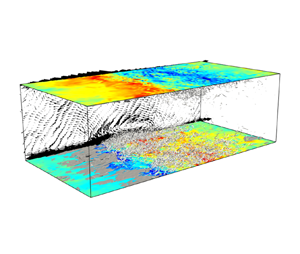
Let us now turn to turbulence structures over the permeable wall. Instantaneous flow and thermal structures are shown at  $Re_b=8\times 10^3$ and $Re_b=4\times 10^4$ in the permeable case ( $\beta u_b=0.5$) in figure 6. The grey objects represent the small-scale vortex structures identified in terms of the positive isosurfaces of the second invariant of the velocity gradient tensor $Q=-(\partial u_{i}/\partial x_{j})(\partial u_{j}/\partial x_{i})/2$, and the dark-grey objects show the high-temperature regions, $\theta '>0$. At $Re_b=8\times 10^3$, we detect almost the same turbulence structures as those commonly observed in wall turbulence. The streamwise vortices near the walls appear roughly homogeneously distributed in the wall-parallel directions. On the contrary, at $Re_b=4\times 10^4$ (for which the ultimate state has been observed) very different large-scale turbulence structures in the form of spanwise-aligned rollers which are propagating downstream can be seen. The colour in the figures represents the level of the wall-normal velocity on the permeable walls, exhibiting strong coherence in the spanwise direction. The small-scale vortex structures cluster around the blowing region, whereas high temperature concentrates in the suction region. The vectors on the plane $z/h=0$ show the spanwise-averaged velocity fluctuations, $({\langle u \rangle }_{z}-{\langle u \rangle }_{xzt},{\langle v \rangle }_{z})$, indicating large-scale spanwise rolls with the length scale comparable with the channel half-width $h$. This remarkable turbulence modulation originates from the Kelvin–Helmholtz type of shear-layer instability over a permeable wall (Jiménez et al. Reference Jiménez, Uhlmann, Pinelli and Kawahara2001).

Figure 6. Instantaneous flow and thermal structures in the permeable case ( $\beta u_{b}=0.5$) for $Pr=1$ at (a) $Re_{b}=8\times 10^{3}$ and (b) $Re_{b}=4\times 10^{4}$. The grey and dark-grey objects represent the isosurfaces of the positive second invariant of the velocity gradient tensor, (a) $Q/(u_{\tau }/h)^2=2\times 10^{3}$ and (b) $Q/(u_{\tau }/h)^2=3\times 10^{4}$, and of the temperature fluctuation (a) $\theta '/\theta _{\tau }=4$ and (b) $\theta '/\theta _{\tau }=6$, respectively. The colour in the top and bottom planes represents the level of the wall-normal velocity on the walls $y/h=\pm 1$. The vectors in the side plane at $z/h=0$ indicate the spanwise-averaged velocity fluctuations $({\langle u \rangle }_{z}-{\langle u \rangle }_{xzt},{\langle v \rangle }_{z})$.
By their linear stability analyses, Jiménez et al. (Reference Jiménez, Uhlmann, Pinelli and Kawahara2001) have shown that the mean turbulent velocity profile in plane channel flow (including background eddy viscosity) can be unstable to infinitesimal disturbances of finite streamwise wavenumber over a permeable wall for the permeability parameter  $\beta > \beta _c$, $\beta _c$ being a critical value. The origin of this instability has been identified as the Kelvin–Helmholtz mechanism in a free shear layer by analytically relating an unstable eigensolution in piecewise-linear inviscid flow over a permeable (free-slip) plane of $\beta >0$ with the eigensolution of the Kelvin–Helmholtz instability at $\beta \rightarrow \infty$. Since the large-scale spanwise rolls in permeable-channel flow arise from the Kelvin–Helmholtz instability, they should exhibit similar properties to those of turbulence structures in free shear layers, such as a mixing layer or a jet. Now, in a self-similar turbulent mixing layer, large-scale spanwise vortical structures with a length scale comparable to the shear-layer thickness appear, inducing velocity fluctuations of the order of the velocity difference across the layer, such that the Taylor dissipation law holds (see e.g. Rogers & Moser Reference Rogers and Moser1994). In the bulk region of turbulent permeable-channel flow, as in free shear layers, the large-scale rolls with a length scale $h$ (corresponding to the free-shear-layer thickness), which undergo the velocity difference of $O(u_{b})$ (corresponding to the velocity difference across the free shear layer), can induce velocity fluctuations of $O(u_{b})$, as shown in figure 5(d,f). Accordingly, the Taylor dissipation law $\epsilon \sim u_{b}^{3}/h$ can hold in this case, and the total energy budget equation (3.4) provides us with $c_{f}\sim Re_b^0$.
Figure 7 shows the spanwise-averaged instantaneous temperature and streamwise velocity in the viscous sublayer. The white isolines,  ${\langle u \rangle }_{z}/u_{\tau }=0$– $4$ and ${\langle \theta \rangle }_{z}/\theta _{\tau }=0$– $4$, indicate the thermal conduction layer and the (viscous) linear sublayer. Note that the null isolines cannot be observed except for the wall surface, implying no flow separation from the wall. At $Re_b=4\times 10^4$, the temperature and velocity distributions near the wall differ greatly from those at $Re_b=8\times 10^3$, and significantly large-amplitude temperature and velocity fluctuations are induced even in the close vicinity of the wall, $(y+h)/(\nu /u_{\tau })\sim 10^0$. The near-wall low-temperature and low-velocity fluids are blown up from the permeable wall, while the high-temperature and high-velocity fluids are sucked towards the wall, inducing events with large turbulent heat flux and Reynolds shear stress. In spite of such significant enhancement of heat and momentum transfer, there is no flow separation over the permeable wall (see figure 7d) unlike in flows over a rough wall (see e.g. figure 10e in MacDonald et al. Reference MacDonald, Hutchins and Chung2019a). This is because the build up of high pressure is counteracted by wall transpiration in the case of a permeable wall. Pressure fluctuations and resulting flow separation yield dissimilarity between heat and momentum transfer as observed in a channel with surface roughness. In permeable-channel flow, however, the absence of flow separation implies the similarity between heat and momentum transfer. Therefore, heat transfer can also be enhanced by the large-scale spanwise rolls comparably with momentum transfer, so that temperature fluctuations are of the order of $\theta _{b}$ (see figure 5b). As a consequence, the wall-normal heat flux scales with $u_{b}\theta _{b}$, leading to the ultimate scaling $St\sim Re_b^0$.

Figure 7. Spanwise-averaged instantaneous (a,b) temperature  ${\langle \theta \rangle }_{z}/\theta _{\tau }$ and (c,d) streamwise velocity ${\langle u \rangle }_{z}/u_{\tau }$ near the lower wall at the same instant as in figure 6 in the permeable case ( $\beta u_{b}=0.5$). The white lines indicate the isolines of ${\langle \theta \rangle }_{z}/\theta _{\tau }=0$– $4$ and ${\langle u \rangle }_{z}/u_{\tau }=0$–4. (a,c) $Re_{b}=8\times 10^{3}$, (b,d) $Re_{b}=4\times 10^{4}$.
Finally, following the argument in Kawano et al. (Reference Kawano, Motoki, Shimizu and Kawahara2021), we would like to suggest the possibility of the ultimate state in practical applications. Let us consider a wall perforated with many fine holes connected to an adjacent constant-pressure plenum chamber. On such a porous wall the fluid is expected to move into or out of the wall in the wall-normal direction through the holes, implying a nearly zero wall-parallel velocity component in the wall plane. Supposing the flow through the holes to be laminar Hagen–Poiseuille flow, the permeability parameter  $\beta$ can be expressed rigorously as $\beta =d^{2}/(32\nu l)$, and the dimensionless permeability parameter is given by
 \begin{equation} \beta u_{b} {=} \frac{1}{32}{\left( \frac{d}{h} \right)}^{2}\frac{h}{l}Re_{b}, \end{equation}
where  $d$ and $l$ represent the diameter of the holes and the thickness of the wall, respectively. Taking into consideration that all the pressure power on the permeable wall in channel flow should be consumed to drive the viscous flow in the holes, the mean velocity $v_m$ in the holes would be comparable with the r.m.s. wall-normal velocity $v_{rms}$ on the permeable wall (Kawano et al. Reference Kawano, Motoki, Shimizu and Kawahara2021). Let us further suppose that the thickness $l$ of the porous wall is of the order of the channel half-width $h$. Substitution of $l/h\sim 1$ in (4.1) yields $d/h\sim {(\beta u_{b})}^{1/2}Re_{b}^{-1/2}$. Thus, the porous wall with the geometry of $l/h\sim 1$ and $10^{-3}\lesssim d/h\lesssim 10^{-2}$ could be characterised by the permeability parameter $\beta u_{b}\sim 10^0$ at $10^{4}\lesssim Re_{b}\lesssim 10^{6}$, where the ultimate state should be observed. The mean velocity in the holes could be estimated to be $v_{m}\sim 10^{-2}u_{b}$, since the r.m.s. wall-normal velocity on the permeable wall is approximately 1 % of $u_{b}$ at $Re_b\sim 10^4$ for $\beta u_{b}=0.5$ (see figure 5f). At $10^{4}\lesssim Re_{b}\lesssim 10^{6}$, the Reynolds number of the flow in the holes, $v_{m}d/\nu \sim 10^{-2}u_{b}d/\nu \sim 10^{-2}Re_{b}d/h$, is in the range $10^{0}\lesssim v_{m}d/\nu \lesssim 10^{1}$, where the flow is laminar and can be expected to fulfil the ‘Darcy law’. Therefore, we believe that the ultimate state can be achieved in the above realistic wall-flow configuration.
5. Summary and outlook
We have investigated turbulent heat and momentum transfer numerically in internally heated permeable-channel flow with a constant bulk mean velocity and temperature,  $u_b$ and $\theta _b$, for $Pr=1$. On the permeable walls at $y=\pm h$, the wall-normal velocity is assumed to be proportional to the local pressure fluctuations, i.e. $v(y=\pm h)=\pm \beta p/\rho$.
In the permeable channel ( $\beta u_{b}=0.5$), we have found the transition of the scaling of the Stanton number $St$ and the friction coefficient $c_{f}$ from the Blasius empirical law $St\approx c_{f}\sim Re_{b}^{-1/4}$ to the ultimate state of $St\sim Re_b^0$ and $c_{f}\sim Re_b^0$ at the bulk Reynolds number $Re_b\sim 10^4$. At $Re_b\lesssim 10^{4}$, there are no significant changes in turbulence statistics or structures from the impermeable case ( $\beta u_b=0$). The ultimate state found at $Re\gtrsim 10^{4}$ is attributed to the appearance of large-scale spanwise rolls stemming from the Kelvin–Helmholtz type of shear-layer instability over the permeable wall. On the permeable wall surface, the blowing and suction are excited by the Kelvin–Helmholtz wave which is roughly uniform in the spanwise direction. Near-wall low-temperature and low-velocity fluids are blown up from the permeable wall, while the high-temperature and high-velocity fluids are sucked towards the wall, largely producing the turbulent heat flux and the Reynolds shear stress. Such remarkable turbulence modulation extends to the close vicinity of the wall, $|y\pm h|/(\nu /u_{\tau })\sim 10^{0}$. Unlike in the case of rough walls, there is no flow separation, so that heat transfer is enhanced in a way comparable to momentum transfer. The key to the achievement of the ultimate state in permeable-channel flow is the significant heat and momentum transfer enhancement without flow separation by large-scale spanwise rolls of the length scale of $O(h)$. The large-scale rolls can induce the large-amplitude velocity fluctuations of $O(u_{b})$ as in free shear layers and they can similarly induce the large-amplitude temperature fluctuations of $O(\theta _{b})$, leading to the Taylor dissipation law $\epsilon \sim u_{b}^{3}/h$ (or equivalently $c_{f}\sim Re_b^0$) and to the ultimate scaling $q_w/(\rho c_{p})\sim u_{b}\theta _{b}$ (or equivalently $St\sim Re_b^0$).
In this study, the ultimate state has been achieved in internally heated permeable-channel flow for the permeability parameter  $\beta u_b=0.5$ and the streamwise period $L_{x}=2{\rm \pi} h$. If we consider a different thermal configuration, e.g. constant temperature difference $\Delta \theta$ between the permeable walls, the same large-scale rolls appear to induce large-amplitude temperature fluctuations of $O(\Delta \theta )$, so that the ultimate scaling $q_w/(\rho c_{p})\sim u_{b}\Delta \theta$ should be achieved as well. Concerning the dependence of the ultimate state on $\beta u_b$ and $L_{x}$, our preliminary study has shown that a slight reduction to $\beta u_b=0.45$ delays the onset of the ultimate state until $Re_b\sim 2\times 10^4$ and that the longer $L_x=4{\rm \pi} h$ can occasionally accommodate the larger streamwise wavelength of the spanwise rolls, yielding the lower onset $Re_b$ and the greater value of the prefactor in the ultimate scaling. A detailed examination is left for a future study.
Acknowledgements
We are grateful to Professor M. Uhlmann for his useful comments on this paper.
Funding
This work was supported by the Japanese Society for Promotion of Science (JSPS) KAKENHI Grant Numbers 19K14889 and 18H01370.
Declaration of interests
The authors report no conflict of interest.


 Open access