


Crossref Citations
This article has been cited by the following publications. This list is generated based on data provided by Crossref.
JIN, Xu
LI, Guoxin
MENG, Siwei
WANG, Xiaoqi
LIU, Chang
TAO, Jiaping
and
LIU, He
2021.
Microscale comprehensive evaluation of continental shale oil recoverability.
Petroleum Exploration and Development,
Vol. 48,
Issue. 1,
p.
256.
CHEN, Ming
GUO, Tiankui
XU, Yun
QU, Zhanqing
ZHANG, Shicheng
ZHOU, Tong
and
WANG, Yunpeng
2022.
Evolution mechanism of optical fiber strain induced by multi-fracture growth during fracturing in horizontal wells.
Petroleum Exploration and Development,
Vol. 49,
Issue. 1,
p.
211.
Yin, Jinrong
Gong, Yunlei
Zheng, Huaan
Yuan, Hui
Zeng, Zhen
Qin, Wei
Li, Chenghao
Zhou, Yang
and
Ren, Xianyan
2022.
Preparation of hydrophobic and high‐strengthpolymer microspheres based on constructing a “Functionalmonomer‐St‐DVB” copolymer structure:Ultra‐low‐densityproppants.
Journal of Applied Polymer Science,
Vol. 139,
Issue. 29,
Wang, Xingyi
Chang, Xin
Jiang, Yun
Guo, Yintong
and
Wei, Kai
2023.
Study on the Difference of Fracture Extension in Hydraulic Fracturing of Marine and Continental Shales Based on Optical Scanning Technology.
Applied Sciences,
Vol. 13,
Issue. 24,
p.
13250.
Sun, Yuan
Zhou, Chengyu
Li, Yifan
Zhou, Min
Zeng, Linghao
Li, Benhui
Fan, Yuzhu
Bao, Dan
and
Chen, Wenke
2023.
Preparation and properties research of a bifunctional hydrophobic associative polymer drag reduction agent for slick water.
Journal of Applied Polymer Science,
Vol. 140,
Issue. 11,
Zhao, En-dong
Lei, Feng-yu
He, Jin-peng
Zhang, Shao-bin
Feng, Xin-yuan
Zhou, Xi-yuan
Guo, De-long
and
Qiao, Xing-yu
2023.
Proceedings of the International Field Exploration and Development Conference 2022.
p.
6468.
Sun, Ning
Gao, Mingwei
Liu, Jiawei
Zhao, Guang
Ding, Fei
You, Qing
and
Dai, Caili
2023.
A novel temperature-resistant fracturing fluid for tight oil reservoirs: CO2-responsive clean fracturing fluid.
Colloids and Surfaces A: Physicochemical and Engineering Aspects,
Vol. 665,
Issue. ,
p.
131247.
Gee, Bruce
and
Gracie, Robert
2024.
The influence of turbulence and inertia in radial fracture flow.
Journal of Fluid Mechanics,
Vol. 981,
Issue. ,
Wang, Menglong
Tian, Lin
Wu, Jinghao
Cao, Yunxing
Wang, Li
Shi, Bin
Sun, Mingyue
Liu, Shimin
and
Hu, Yunbing
2024.
Fracture Properties of Nitrogen–Slick Water Composite Fracturing in Coal Reservoir.
Processes,
Vol. 12,
Issue. 9,
p.
1949.
Ding, Mingchen
and
He, Mingming
2024.
Effect of Water-Induced Rock Softening on Rock Anisotropy During Drilling Process.
Rock Mechanics and Rock Engineering,
Vol. 57,
Issue. 10,
p.
8193.
Zhao, Mingwei
Yan, Xiaowei
Zhang, Liyuan
Yan, Ruoqin
Liu, Shichun
Ma, Zhenfeng
and
Dai, Caili
2024.
Development of degradable fiber slickwater system and enhanced proppants-carrying mechanism.
Geoenergy Science and Engineering,
Vol. 237,
Issue. ,
p.
212822.
Wang, Feng
and
Surace, Cecilia
2024.
Research and Application of Coal Seam Permeability Improvement Technology by Sectional Directional Hydraulic Fracturing.
Shock and Vibration,
Vol. 2024,
Issue. ,
p.
1.
Liu, Hongtao
Huang, Longzang
Liu, Junyan
Li, Lili
and
Wang, Lang
2024.
Advances in Energy Resources and Environmental Engineering.
p.
1225.
Luo, Yunxiang
Li, Na
Zheng, Jun
Yang, Shuangyu
and
Wu, Yan
2024.
Secondary utilization of self-suspending proppant's coating polymer: Enhance oil recovery.
Geoenergy Science and Engineering,
Vol. 243,
Issue. ,
p.
213301.
1 Introduction
Hydraulic fracturing is one of the essential technologies behind the gas shale revolution, which started in the early years of this century. Indeed, effective production of hydrocarbons from low-porosity shale deposits relies on placing, in successive stages, tens to hundreds of hydraulic fractures in the horizontal section of each borehole (Patterson, Yu & Wu Reference Patterson, Yu and Wu2018). This hydraulic fracturing treatment requires, however, to inject water at a very high rate from the surface into kilometre-long boreholes, in order to induce sufficient fracture width to place the proppant. Furthermore, the treatment design involves the simultaneous propagation of several fractures from perforation clusters, thus imposing further requirement for large injection rate. To reduce the energy demand and keep the operation economically viable, heavy-molecular-weight polymers are added to the water to substantially reduce drag in the turbulent regime. The effect of these drag-reducing agents saturates at relatively low polymer concentration, leading to the emergence of a maximum drag reduction (MDR) asymptote when the Reynolds number $Re$ is approximately 103.
The main issue considered by Lecampion & Zia (Reference Lecampion and Zia2019), henceforth LZ, is the influence on the propagation of a radial hydraulic fracture of the drag-reduction agents in combination with the large injection rate. They tackle this question through a theoretical effort that involves the development of models applicable to slickwater fracturing. Their analysis concludes, however, that flow in the fracture is inherently laminar with the turbulent regime restricted at most to the first few minutes of injection.
2 Overview
2.1 Mathematical model
Two fundamental equations govern the fracture aperture $w$ and the fluid pressure $p$: a non-local elasticity equation and the nonlinear Reynolds lubrication equation. Together with the boundary and initial conditions and the propagation criterion, they provide a complete formulation of the evolution problem (Detournay Reference Detournay2016). Two regimes of flow are considered by LZ for slickwater hydraulic fracturing: the viscous laminar regime with friction factor $f\sim Re^{-1}$ and the turbulent MDR regime for which $f\sim Re^{-0.7}$. The mathematical model depends on Young’s modulus $E$, Poisson’s ratio $\unicode[STIX]{x1D708}$ and toughness $K_{Ic}$ for the rock, and viscosity $\unicode[STIX]{x1D707}$, density $\unicode[STIX]{x1D70C}$ and index $n$ for the fluid, where $n=1$ for laminar flow and $n=0.7$ in the turbulent MDR regime, as well as on the injection rate $Q$. However, to avoid carrying numerical factors in the definitions of the length and time scales below, the following alternative material parameters are introduced:
2.2 Tip asymptotic solution
Asymptotics of the solution near the advancing tip of a hydraulic fracture have the structure of a travelling wave. Hence, near the crack front, the dependence of the solution on position and time reduces to a dependence of the asymptotic fields on the distance from the crack front, with the current local-front velocity $V$ acting as a time-dependent parameter. Asymptotic solutions were initially restricted to situations involving the laminar flow of a Newtonian fluid, one-dimensional leak-off and linear elastic fracture mechanics (Garagash, Detournay & Adachi Reference Garagash, Detournay and Adachi2011); they have recently been extended to include shear-thinning fluid (Dontsov & Kresse Reference Dontsov and Kresse2018; Moukhtari & Lecampion Reference Moukhtari and Lecampion2018) and turbulent flow (Dontsov Reference Dontsov2016).
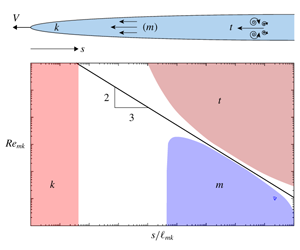
In the spirit of these solutions, LZ construct a multiscale tip asymptote applicable to slickwater hydraulic fracturing. This solution captures three distinct regimes of energy dissipation: (i) close to the tip, a region dominated by dissipation in the creation of new solid surfaces; (ii) an intermediate region dominated by viscous laminar dissipation; and (iii) far from the tip, a region dominated by turbulent MDR flow. The solution is characterized by two independent length scales, $\ell _{mk}$ and $\ell _{tm}$, given by
where $\ell _{tk}$ is a third length scale and $Re_{mk}$ is a characteristic Reynolds number, which both depend on $\ell _{mk}$ and $\ell _{tm}$ only, and $Re_{c}\simeq 1133$.
The crack aperture, in each of the three regions dominated by a particular dissipation, varies as a power law of distance $s$ from the tip: a near-tip toughness $k$-asymptote with ${\hat{w}}\sim s^{1/2}$, an intermediate viscous laminar $m$-asymptote with ${\hat{w}}\sim s^{2/3}$, and a far-tip turbulent MDR $t$-asymptote with ${\hat{w}}\sim s^{20/27}$. Length scales $\ell _{mk}$ and $\ell _{tm}$ are proportional to the bounds of the intermediate $m$-asymptote region, which correspond approximately to $10^{-1}\ell _{mk}<s<\ell _{tm}$. Also the $k$-asymptote exists within distances from the tip less than approximately $10^{-5}\ell _{mk}$. However, as suggested by the above expression for $Re_{mk}$, the intermediate asymptote region shrinks with increasing $Re_{mk}$ to eventually disappear when $Re_{mk}\sim Re_{c}$. Thus, for large characteristic Reynolds numbers, there are only two power-law regions, the $k$-asymptote at $s\lesssim 10^{-5}\ell _{mk}$ and the $t$-asymptote at $s\gtrsim \ell _{tk}$.
The tip length scales $\ell _{mk}$, $\ell _{tm}$ and $\ell _{tk}$ legislate the nature of dissipation near the front of a finite hydraulic fracture and control how the dominant mode of dissipation changes with time. Let $\ell$ denotes the distance from the front over which the autonomous tip solution is applicable; for a penny-shaped fracture, $\ell$ is a constant fraction, say 10 %, of the fracture radius $R$. The key point to recognize is that all the tip length scales defined above increase with time, relative to $\ell$.
At small time, the tip region is effectively fully described by the $t$-asymptote. Under these conditions, the global solution is completely shielded from both the $k$- and the $m$-asymptotes, which exist in a tiny region at the tip. However, as time progresses, the sizes of the tip length scales $\ell _{mk}$, $\ell _{tm}$ and $\ell _{tk}$ increase relative to $\ell$, causing the disappearance of the turbulent MDR asymptote from the tip region of the finite fracture and the progressive emergence of the $m$-asymptote. As long as the $k$-asymptote region is small compared to $\ell$, the global solution does not depend on the toughness. However, further passing of time leads to the growth of the $k$-asymptotic region relative to $\ell$, at the expense of the $m$-asymptote. Thus at large time, the tip region of the finite fracture is dominated by the $k$-asymptote, with the consequence that the fracture propagates in the toughness-dominated regime. If $Re_{mk}$ is larger than $Re_{c}$, the intermediate viscous laminar regime is bypassed, with the $t$-asymptote dominating the tip region at small time and the $k$-asymptote at large time. The figure alongside the title illustrates the region of dominance of each asymptote.
2.3 Penny-shaped fracture
The above classification of the dominance of a particular mode of energy dissipation is based on contrasting length scales $\ell _{mk}$, $\ell _{tm}$ and $\ell _{tk}$ with the size $\ell$ of the tip region. However, it can be recast in terms of time for a radial hydraulic fracture propagating under constant injection rate, through the introduction of time scales expressing transition between regimes of propagation. These time scales are linked to the existence of three similarity solutions for slickwater fracturing, all characterized by a power-law dependence of the fracture radius $R$ on time. In addition to two known similarity solutions (Savitski & Detournay Reference Savitski and Detournay2002), where energy is dissipated exclusively either in viscous laminar flow ( $M$-solution with $R\sim t^{4/9}$) or in the creation of fracture surfaces ( $K$-solution with $R\sim t^{2/5}$), LZ demonstrated the existence of a third similarity solution ( $T$-solution with $R\sim t^{40/87}$) with all the dissipation taking place in the fluid in the turbulent MDR regime. Each similarity solution is characterized by a dominant tip asymptote; for example, the tip asymptote viewed at the fracture scale is the $t$-asymptote for the $T$-solution.
Transition time scales are deduced naturally from the similarity solutions. Three such scales, $T_{tk}$, $T_{tm}$ and $T_{mk}$, can be determined, but only two are independent:
When measuring time relative to these time scales, it can then be demonstrated that (i) the $T$-solution is the small-time asymptote ( $t/T_{tm}\ll 1$ and $t/T_{mk}\ll 1$), (ii) the $K$-solution is the large-time asymptote ( $t/T_{mk}\gg 1$), and (iii) the $M$-solution is an intermediate-time asymptote when $t/T_{tm}\gg 1$ and $t/T_{mk}\ll 1$, and which exists provided that there is separation of the two time scales, i.e. if $\unicode[STIX]{x1D711}=T_{tm}/T_{mk}\ll 1$.
Numerical simulations confirm that the time scales derived from a scaling analysis provide an adequate measure of the transition time between regimes. The results of two simulations are reported: one with $\unicode[STIX]{x1D711}\simeq 10^{-3}$, which confirms the transition between the $T$- and the $M$-solutions; the other with $\unicode[STIX]{x1D711}\simeq 4$, which describes the transition between the $T$- and the $K$-solutions. These simulations and the time scales indicate that, for plausible values of the rock and fluid parameters and of the injection rate, the turbulent regime is restricted at most to the first few minutes of injection.
3 Future
Advances in theoretical predictions must necessarily rely on further understanding of the rheology of slickwater. As noted by the authors, the addition of heavy-molecular-weight polymers to water increases the viscosity of the fluid, but also introduces a degree of shear thinning and viscoelasticity. While the increase of viscosity is expected to further reduce or even eliminate the turbulent flow regime, the breaking of the polymer chains caused by high downhole temperature or high shear rate could degrade the fluid and thus reduce its capacity to lower drag in the turbulent flow regime. These effects, as well as the progressive damage of the rock at the crack tip, should be considered in future models of slickwater hydraulic fracturing.