


I. INTRODUCTION
As a significant electromagnetic interference, active jamming is a great threat to the survival of guidance radars. It can be classified into active blanket jamming and active deception jamming. By active blanket jamming is meant the suppression noise with high power to reduce signal-to-noise ratio (SNR) of the received signal, while by active deception jamming is meant the electromagnetic decoy as the same characteristic as the real target in time–frequency domain. In order to interfere in various radars with different polarization forms, the two types of active jamming always take the form of circular polarization [Reference Gong1–Reference Hurtado, Xiao and Nehorai3].
Since for the difference between active jamming and the target in polarization field, the application of polarization technology for countering active jamming is drawing more and more scholars' attention. The main methods for countering active jamming are polarization encoding [Reference Qiao4, Reference Tao5], hypercomplex and spatiotemporal-polarization processing [Reference Tao6], and polarization filtering [Reference Poelman7–Reference Wang9]. The first two methods are difficult to apply in practical engineering, because they need complex systems and not meet the requirement of miniaturization. While which is studied more extensively, the method of polarization filter can form single-notch or multi-notch at the polarization angle of jamming through polarization diversity. So the radar can receive normal target echo, but less electromagnetic wave signal from active jamming, certainly the SNR of the received signal is greatly improved. But an additional bulky polarization transformation device must be utilized to make the polarization form of the radar against that of the present active jamming. A null phase-shift polarization filtering method was presented by Mao and Liu [Reference Mao and Liu10]. Adaptively adjusting the parameters of polarization filter according to the polarization form of jamming and compensating the error of phase and amplitude after filtering, it can reduce the error between the filtered signal and the real target signal, and not disturb coherent processing of the filtered signal. But it is also difficult to meet the requirements of radar seekers, because it still requires a large amount of front-end equipment to deal with the variation of polarization forms. An improved method based on the research of literature [Reference Mao and Liu10] was proposed [Reference Dai, Li and Liu11]. The polarization parameters of echo signal are obtained just by analyzing the modulation influence of spatial polarization of the guidance radar with a single polarization antenna, and then it does the same filtering processing as literature [Reference Mao and Liu10]. The method seems to reduce complexity of the front-end equipment of polarization radars. But the gain of orthogonal polarization pattern for a single polarization antenna is usually 30 dB lower than that of main polarization pattern, evidently the reliability of the obtained polarization parameters is greatly lowered and the result of countering active jamming is also not desirable enough.
With the development of antenna technology, multi-polarization antennas with common aperture [Reference Jungsuek and Kamal12, Reference Park13] are no longer a problem, which will greatly accelerate the application of polarization anti-jamming technology to guidance radars. According to the public reporting, there is a dual-polarization radar seeker at 94 GHz carried by brimstone missile on active service, which is developed by a MBDA missile system [14]. A polarization ECCM technique was proposed to counter active blanket jamming based on dual-polarization radar [Reference Varga and DeWolf15]. Because of neglecting the cross-polarized component of the target echo and not being compensated, the method does poorly in angle measurement. Based on the practical engineering application of dual-polarization radar seekers, this paper puts forward an adaptive polarization cancellation method to counter active jamming. Without increasing any other hardware more, the method can achieve good cancellation effects on both active blanket jamming and active deception jamming, so it is very meaningful for engineering application.
The remainder of this paper is organized as follows. Signal models of a real target and active jamming are introduced in Section II. The characteristic of the dual-polarization radar is analyzed and the practical signals obtained by the dual-polarization radar are described in Section III. Then Section IV addresses the principle of adaptive polarization cancellation, and discusses the influence factors of cancellation result. Experimental results and analysis are shown in Section V. Finally, Section VI concludes the paper.
II. SIGNAL MODELS OF RADAR TARGET AND ACTIVE JAMMING
In a horizontal and vertical polarization coordinate system, electromagnetic wave signal transmitted by radar can be described as
 $${\bi e}_{\bi t}({\bi t}) = g\sqrt {\displaystyle{{P_t} \over {4\pi L_t}}} e^{j2\pi f_ct}s(t){\bi h}{\rm,}$$
where g is the gain of radar antenna, P t is the peak power of transmitted signal, L t is the comprehensive loss, f c is the carrier frequency, s(t) is the modulation function of radar signal, and h = [h H h V ] is the polarization form of the antenna. For convenience of description, the transmitted signal can be simplified as
 $${\bi e}_{\bi t}({\bi t}) = gA_t{\bi h}{\rm,}$$
where $A_t = \sqrt {(P_t/4\pi L_t)} e^{j2\pi f_ct}s(t)$
.
$A_t = \sqrt {(P_t/4\pi L_t)} e^{j2\pi f_ct}s(t)$
.
So at the receiving port of radar antenna, the backscattering echo from a target can be described as
 $${\bi e}_{\bi i}({\bi t}) = \displaystyle{g \over {4\pi R^2}}A_t(t - \tau )e^{j2\pi f_d(t - \tau )}{\bi hS}{\rm.}$$
Here R represents the slant range between the radar and the target; f d represents the Doppler frequency caused by target motion; τ = 2R/c represents the delay time of target echo, c represents the speed of light;
 $${\bi S}\;{\rm =}\;\left[ {\matrix{ {S_{HH}} & {S_{HV}} \cr {S_{VH}} & {S_{VV}} \cr}} \right]$$
denotes the polarization scattering matrix (PSM) of the target.
While the signal from active jamming at the receiving port of radar antenna can be described as
 $${\bi e}_{\bi J}({\bi t}) = J(t){\bi h}_{\bi J}{\rm.}$$
where h J = [h jH h jV ] denotes the polarization form of active jamming, which is usually circular polarization; J(t) is the modulation signal of active jamming.
As is mentioned above, the practical signal received by radar consists of that from the target and that from active jamming. It can be expressed as
 $$E_r(t) = \displaystyle{{k_{RF}g} \over {L_r}}\left[ {{\bi e}_{\bi i}({\bi t}) + {\bi e}_{\bi J}({\bi t})} \right]{\bi h}^{\bi T} + n(t){\rm,}$$
where k RF represents the RF amplification coefficient of radar receiver, L r is the loss of the receiver, and n(t) is the receiver noise that always obeys normal distribution.
III. CHARACTERISTIC OF DUAL-POLARIZATION RADAR
Formulated by Sinclair, PSM can absolutely denote the polarization characteristic of a target, which is able to be obtained by full polarization radar [Reference Lee and Pottier16]. It is defined as
 $${\bi S} = \left[ {\matrix{ {S_{HH}} & {S_{HV}} \cr {S_{VH}} & {S_{VV}} \cr}} \right] = e^{j\omega} \left[ {\matrix{ { \vert S_{HH} \vert} & { \vert S_{HV} \vert e^{j(\emptyset _{HV} - \omega )}} \cr { \vert S_{VH} \vert e^{j(\emptyset _{VH} - \omega )}} & { \vert S_{VV} \vert e^{j(\emptyset _{VV} - \omega )}} \cr}} \right]{\rm,}$$
where S
HV
denotes the vertical polarization backscattering coefficient of the target irradiated by horizontal polarization wave, S
HH
, S
VH
, and S
VV
are the same definition as S
HV
, ω is the phase of S
HH
, $\emptyset _{HV}$
,
$\emptyset _{HV}$
, $\emptyset _{VH},$
and
$\emptyset _{VH},$
and $\emptyset _{VV}$
are respective phases of S
HV
, S
VH
, and S
VV
.
$\emptyset _{VV}$
are respective phases of S
HV
, S
VH
, and S
VV
.
In practical engineering applications, dual-polarization radars are commonly used. They have the ability of single polarization transmission, but dual-polarization channels receiving simultaneously. Taking vertical polarization transmission for example, only half PSM of the target can be obtained, and it is simplified as
 $${\bi S} = [\matrix{ {S_{VH}} & {S_{VV}} \cr} ]{\rm.}$$
Here S VV represents the co-polarized component that includes the same echo information as the conventional single polarization radar; S VH represents the cross-polarized component, which denotes the converting polarization ability of the target and is the main polarization characteristic obtained by dual-polarization radars.
For typical radar targets, such as aircrafts, warships, tanks, buildings, and so on, the polarization form of their backscattering electromagnetic wave is greatly related to that of the incident electromagnetic wave. It means that the polarization form of their backscattering electromagnetic wave is mainly as the same as that of the incident electromagnetic wave. In other words, their co-polarized ability is much greater than the converting polarization ability. So the value of S VV is much greater than S VH , and that is to say |S TVV | ≫ |S TVH | [Reference Dai17]. Here S TVV and S TVH are respectively S VV and S VH of the targets.
For active jamming, it is usually of circular polarization. Thus, its polarization form can be expressed as h J = [j.sinwt coswt] or h J = [j.sinwt coswt], which respectively denote left- and right-hand circular polarizations. The powers received by vertical- and horizontal polarization antennas from active jamming with standard circular polarization are equal, but they are 3 dB lower than that received by the matching circular polarization antenna. If active jamming is considered as a special target, it is evidently |S JVV | = |S JVH |, and the difference between S JVV and S JVH is just the phase [Reference Dai, Wang and Li2]. Here S JVV and S JVH are respectively S VV and S VH of active jamming. Therefore, the method of polarization cancellation can be introduced to suppress active jamming. Note that the polarization form of active jamming in practical engineering is not usually a standard circle, so the axial ratio of the circle is just close to but not 1. That is to say, it is usually |S JVV | ≈ |S JVH | in practical engineering.
According to Section II, the signal models for dual-polarization radars should be developed as follows. When the radar is being interfered with by active jamming, the signal received by vertical polarization channel can be described as
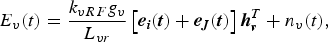 $$E_v(t) = \displaystyle{{k_{vRF}g_v} \over {L_{vr}}}\left[ {{\bi e}_{\bi i}({\bi t}) + {\bi e}_{\bi J}({\bi t})} \right]{\bi h}_{\bi v}^T + n_v(t){\rm,}$$
where k vRF is the RF amplification coefficient of vertical polarization channel, g v is the gain of vertical polarization antenna, L vr is the receiver loss of vertical polarization channel, h v is the polarization form of vertical polarization antenna, and n v (t) is the noise of vertical polarization channel.
Substituting equations (3) and (4) into (8), equation (9) can be obtained.
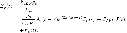 $$\eqalign{ E_v(t) &= \displaystyle{{k_{vRF}g_v} \over {L_{vr}}} \cr & \quad \left[ {\displaystyle{{g_v} \over {4\pi R^2}}A_t(t - \tau )e^{j2\pi f_d(t - \tau )}S_{TVV} + S_{JVV}J(t)} \right] \cr & \quad+ n_v(t).}$$
In the same way, the signal received by horizontal polarization channel can be expressed as
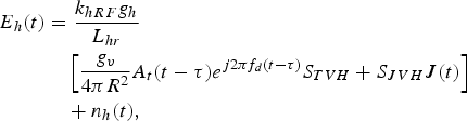 $$\eqalign{ E_h(t) &= \displaystyle{{k_{hRF}g_h} \over {L_{hr}}} \cr & \quad \left[ {\displaystyle{{g_v} \over {4\pi R^2}}A_t(t - \tau )e^{j2\pi f_d\left( {t - \tau} \right)}S_{TVH} + S_{JVH}J(t)} \right] \cr & \quad + n_h(t),}$$
where k hRF is the RF amplification coefficient of horizontal polarization channel, g h is the gain of horizontal polarization antenna, L hr is the receiver loss of horizontal polarization channel, and n h (t) is the noise of horizontal polarization channel.
IV. ADAPTIVE POLARIZATION CANCELLATION OF ACTIVE JAMMING
A) Principle of adaptive polarization cancellation
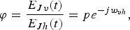
From equations (9) and (10), the signals obtained by vertical- and horizontal channels differ in both amplitude and phase. To make the active jamming be completely cancelled, the amplitude and phase of active jamming signals obtained by the two channels should be made consistent. So the weight coefficient of polarization cancellation can be defined as
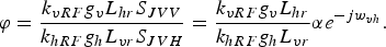 $$\varphi = \displaystyle{{k_{vRF}g_vL_{hr}S_{JVV}} \over {k_{hRF}g_hL_{vr}S_{JVH}}} = \displaystyle{{k_{vRF}g_vL_{hr}} \over {k_{hRF}g_hL_{vr}}}\alpha e^{ - jw_{vh}}.$$
Here α = |S JVV |/|S JVH |, represents the axial ratio of circular polarization; w vh is the phase difference between S JVV and S JVH .
Then, the polarization cancellation method can be described as
 $$z(t) = E_v(t) - \varphi E_h(t).$$
Substituting equations (9) and (10) into (12), It can be developed as
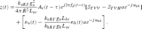 $$\eqalign{z(t) = & \displaystyle{{k_{vRF}g_v^2} \over {4\pi R^2L_{vr}}}A_t(t - \tau )e^{j2\pi f_d(t - \tau )}[S_{TVV} - S_{TVH}\alpha e^{ - jw_{vh}}] \cr & + \left[ {n_v(t) - \displaystyle{{k_{vRF}g_vL_{hr}} \over {k_{hRF}g_hL_{vr}}}n_h(t)\alpha e^{ - jw_{vh}}} \right].}$$
From equation (13), active jamming can be completely eliminated in theory, but the signal power received from the target is changed. It will reduce the angle-measuring accuracy of monopulse radars with sum and difference patterns of amplitude, because the method of monopulse angle measurement is sensitive for the amplitude of the target signal [Reference Barton18, Reference Skolnik19].
In practical engineering, both amplitude difference and phase difference between vertical and horizontal channels of the dual-polarization radar caused by the hardware system can be adjusted easily as was described in prior publications [Reference Gu, Liang and Yu20, Reference Jeffrey21]. So the weight coefficient of polarization cancellation can be simplified as
 $$\varphi = \displaystyle{{E_{Jv}(t)} \over {E_{Jh}(t)}} = pe^{ - jw_{vh}},$$
where E Jv (t) represents the signal of active jamming obtained by vertical channel, E Jh (t) represents that obtained by horizontal channel, and
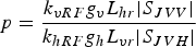 $$p = \displaystyle{{k_{vRF}g_vL_{hr} \vert S_{JVV} \vert} \over {k_{hRF}g_hL_{vr} \vert S_{JVH} \vert}} $$
represents the amplitude ratio of the signals obtained by the two orthogonal polarization channels. When the dual-polarization radar does not emit electromagnetic wave, its received signal must be only from active jamming. So E Jv (t) and E Jh (t) can be easily obtained.
In equation (12), E h (t) = E Jh (t) + E Th (t), where E Th (t) is the horizontal component of the target echo, thus it is regarded as jamming signal and eliminated in error. To improve angle-measuring accuracy, the target signal power after polarization cancellation should be adjusted as
 $$z(t) = E_v(t) - \varphi E_h(t) + \varphi (E_h(t) - E_{Jh}(t)) = E_v(t) - E_{Jv}(t).$$
For monopulse radars, equation (15) must be used in both sum signal and difference signal simultaneously. Eliminating most active jamming signal and adjusting the power change introduced by polarization cancellation, the method will greatly improve the angle-measuring accuracy. But E v (t) and E Jv (t) are not obtained at the same time, so it may introduce extra phase difference and the target signal after it cannot retain coherent perfectly.
Therefore, equations (12) and (13) should be chosen to counter active jamming when the radar needs coherent integration. Because the same value of φ is used in the whole integration period, the phase of target signal will keep consistent and the polarization cancellation method will not reduce the gain of coherent integration. In addition, the co-polarized component is much greater than the cross-polarized component for typical radar targets and the axial ratio of active jamming is usually close to 1, so the signal power after polarization cancellation received from the target is just made a little change. It has little influence for subsequent signal processing besides monopulse angle measurement.
The proposed method above needs not any parameters of active jamming in prior, and can adaptively obtain the weight coefficient of polarization cancellation in time. Then, it adaptively does different cancellation processing according to requirements, equation (12) for coherent integration and equation (15) for monopulse angle measurement.
B) Influence factors of polarization cancellation
According to equation (12), the weight coefficient φ is unquestionably a key factor related to the efficiency of polarization cancellation. In the process of adaptive polarization cancellation, φ is obtained from the actual environment in real time, then it will be used for the following echo pulses. So there are some errors between the obtained φ and the real φ of every pulse, certainly the loss of polarization cancellation will be introduced.
In this paper, the gain of signal-to-interference-and-noise ratio (G SINR ) is defined as the improvement factor to evaluate the efficiency of polarization cancellation. It is expressed as
 $$G_{SINR} = SINR_{out} - SINR_{in},$$
where SINR in represents signal-to-interference-and-noise ratio (SINR) of input signal, and SINR out represents SINR of output signal. In addition, SINR is defined as
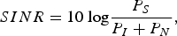 $$SINR = 10\;{\rm log}\displaystyle{{P_S} \over {P_I + P_N}},$$
where P S represents the power of the target signal, P I represents that of interference, and P N represents that of noise.
When SINRs of two input signals are −7 and −3 dB, their three-dimensional diagrams of G SINR after polarization cancellation with the change of amplitude and phase errors of φ are respectively shown in Figs 1 and 2. Here, the x-axis denotes the amplitude error Δp, the y-axis denotes the phase error Δw vh , and the z-axis denotes G SINR . It is evidently that G SINR is extremely sensitive to Δp and decays rapidly with the increase of Δp, but not sensitive to Δw vh .
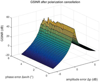
Fig. 1. G SINR with the change of amplitude and phase errors of φ, when SINR = −7 dB.
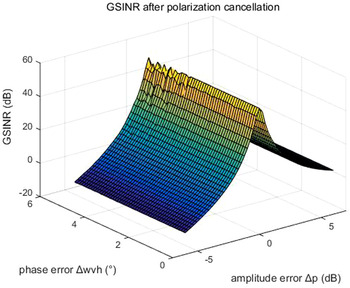
Fig. 2. G SINR with the change of amplitude and phase errors of φ, when SINR = −3 dB.
On the other hand, noise and interference are surely influence factors of polarization cancellation. Thus, the influence of SINR is also analyzed in Fig. 3, where the x-axis represents SINR of the input signal, and the y-axis represents G SINR . The diagram shows that G SINR increases with the increase of SINR, and G SINR reaches the peak when SINR is approximately 10 dB, then decays slowly. Note that SINR most depends on the radar system and the practical scene, so it is difficult to be improved.
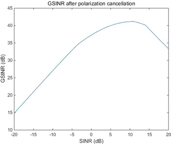
Fig. 3. G SINR with the change of SINR.
In the two simulations, the radar signal is linear frequency modulation signal, and the ratio of co-polarized-to-cross-polarized component of the target signal is 6. According to the analysis above, it is obviously that the amplitude value of φ is the most sensitive factor, so ensuring real time update of φ and reducing its error is very important in the process of polarization cancellation.
V. EXPERIMENTAL RESULTS AND ANALYSIS
In order to prove the effectiveness of the proposed method for countering active jamming, real experimental data obtained by the dual-polarization radar in millimeter wave band is analyzed. In the experiment, an angle reflector is used as the target, and it is approximately 1000 range units far from the radar, then an active blanket jammer and an active deception jammer are respectively used to emit interference signal at the radar.
Their results after the proposed adaptive polarization cancellation for active blanket jamming are shown in Figs 4–6. In which, Fig. 4 is the one-dimensional range profile obtained by vertical polarization transmission and vertical polarization receiving (VV) channel of the dual-polarization radar, Fig. 5 is that obtained by vertical polarization transmission and horizontal polarization receiving (VH) channel, and Fig. 6 is the result after polarization cancellation. From them, the target has been completely drowned by interference signal in the VV channel, but the interference signal is perfectly eliminated and the target is effectively retained after polarization cancellation. Figures 7–9 are the same meaning as above for active deception jamming. Although they are difficult to distinguish from the real target in the VV channel, the deception decoys are also completely eliminated with the retaining of the real target after polarization cancellation.
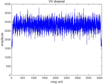
Fig. 4. Range profile of the VV channel for active blanket jamming.
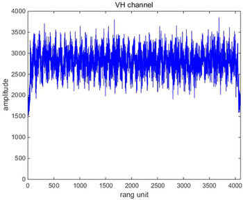
Fig. 5. Range profile of the VH channel for active blanket jamming.
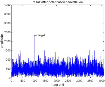
Fig. 6. Polarization cancellation result for active blanket jamming.
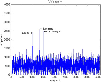
Fig. 7. Range profile of the VV channel for active deception jamming.
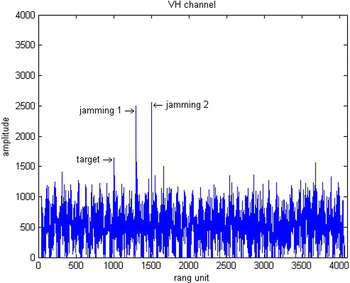
Fig. 8. Range profile of the VH channel for active deception jamming.
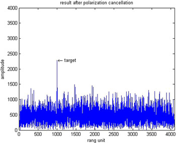
Fig. 9. Polarization cancellation result for active deception jamming.
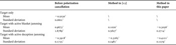
In addition, the comparison of monopulse angle measuring value is given in Table 1. In the experiment, the target and the active deception jammer are located at the same azimuthal direction of −0.5° off the boresight of the radar, while the active blanket jammer is nearly located at 1.5°. Making the angle estimation value acquired by the monopulse method without jamming as the standard value of the real target angle, it is obviously that the method proposed in this paper for countering active jamming can improve the angle-measuring accuracy greatly; and the result is also much better than the method in [Reference Varga and DeWolf15].
Table 1. Comparison of monopulse angle measuring value.
It is important to note that, the projection effect of geometry on the polarization vector is neglected in this paper, but the experimental results show that the proposed method is also quite meaningful.
VI. CONCLUSION
In this paper, a countering method for active jamming is proposed based on dual-polarization radar seeker. Both active blanket jamming and active deception jamming can be eliminated perfectly, and the angle-measuring accuracy of monopulse radars is also improved greatly. Since it needs not any other hardware source more, the proposed method is in the vantage of size and complexity, which is significant for guidance radars. In addition, it can be realized before pulse compression, and does not affect the subsequent signal processing, such as coherent integration and imaging, so it is of a high value for engineering applications.
ACKNOWLEDGEMENT
This work was supported by the National Natural Science Foundation of China (Grant No. U1433126).
 Qiang Zhang received his Ph.D. degree in Signal and Information Processing from the Chinese Academy of Sciences in 2012. He served as a senior engineer at Southwest China Institute of Electronic Technology in 2012–2015. He is now an Associate Professor at the College of Air Traffic Management, Civil Aviation Flight University of China. He is active in the areas of polarization technology, radar system design, image processing, and target recognition.
 Weijun Pan received his Ph.D. degree in Computer Application from Sichuan University, China, in 2012. He is now a professor at College of Air Traffic Management, Civil Aviation Flight University of China. His research interests include radar system, air traffic management, computer application, and safety engineering.


