


1 Introduction
Ultra-intense ultrashort lasers draw great interest in laser–matter interaction research, such as laser acceleration, laser fusion, attosecond sciences, atomic molecular physics, materials science, nuclear physics and astrophysics[ Reference Umstadter1]. With remarkable progresses in chirped pulse amplification (CPA)[ Reference Strickland and Mourou2] and optical parametric chirped pulse amplification (OPCPA)[ Reference Dubietis, Jonušauskas and Piskarskas3], the laser peak power has already reached the order of petawatts (PW, 1015 W)[ Reference Chu, Gan, Liang, Yu, Lu, Wang, Wang, Xu, Lu, Yin, Leng, Li and Xu4– Reference Xu, Yu, Liang, Chu, Hu, Ma, Xu, Wang, Lu, Lu, Yue, Zhao, Fan, Tu, Leng, Li and Xu6]. In order to investigate the physical laws of extreme conditions under stronger lasers, many countries are vigorously developing 10 PW-level laser systems, and have proposed development plans of 100 PW-level laser systems[ Reference Cartlidge7– Reference Bromage, Bahk, Begishev, Dorrer, Guardalben, Hoffman, Oliver, Roides, Schiesser, Shoup, Spilatro, Webb, Weiner and Zuegel9]. The current PW laser systems are based on Ti:sapphire, but are limited by thefact that the size of Ti:sapphire is not large enough to support a peak power of 100 PW or higher. Meanwhile, for Nd:glass based laser systems at 1 μm, it is difficult for the pulse width to reach shorter than 100 fs ; therefore, very high energy is required to achieve 100 PW laser pulses. Compared with CPA, the OPCPA laser system is the most suitable program for 100 PW lasers, as it can support high energy and a short pulse width at the same time. Because the largest size of deuterated potassium dihydrogen phosphate (DKDP) crystals can be up to over 400 mm, the DKDP-based OPCPA system is the most promising candidate for 100 PW lasers. The most powerful pump laser that can provide more than 10 kJ energy is based on Nd:glass, and the broadest gain bandwidth of DKDP pumped by a frequency doubled Nd:glass laser is centered at 910 nm; hence, the seed source for this system must also be centered around 910 nm and the bandwidth should be more than 200 nm to support an ultrashort duration. Different from typical seed lasers with center wavelengths of 800 and 1053 nm[ Reference Yu, Xu, Liu, Li, Li, Liu, Li, Wu, Yang, Yang, Wang, Lu, Leng, Li and Xu10, Reference Guo, Tokita, Yoshii, Nishioka and Kawanaka11], broadband 910 nm laser pulses are rarely obtained directly from commercial lasers. Therefore, nonlinear frequency conversion should be adopted, such as optical parametric amplification (OPA) and second harmonic generation (SHG) processes. For example, a 910 nm laser pulse has been successfully achieved with the OPA process and subsequent SHG process[ Reference Shao, Li, Peng, Wang, Qian, Leng and Li12]. However, for the limited bandwidth of phase-matching in OPA and SHG processes, laser pulses with shorter pulse duration are extremely difficult to obtain directly. It is necessary to further broaden the spectrum to achieve few-cycle or even cycle-level pulses.
To obtain few-cycle pulses, many pulse compression techniques have been developed, such as gas-filled cells[ Reference Hanna, Délen, Lavenu, Guichard, Zaouter, Druon and Georges13, Reference Lavenu, Natile, Guichard, Zaouter, Delen, Hanna, Mottay and Georges14], filamentation[ Reference Hauri, Kornelis, Helbing, Heinrich, Couairon, Mysyrowicz, Biegert and Keller15, Reference Driever, Bigourd, Fedorov, Cornet, Arnold, Burgy, Montant, Petit, Descamps, Cormier, Constant and Zaïr16], bulk condensed media[ Reference Lu, Tsou, Chen, Chen, Cheng, Yang, Chen, Hsu and Kung17, Reference Dubietis, Tamošauskas, Šuminas, Jukna and Couairon18], gas-filled hollow-core fibers (HCFs)[ Reference Jeong, Piccoli, Ferachou, Cardin, Chini, Hadrich, Limpert, Morandotti, Legare, Schmidt and Razzari19– Reference Safaei, Fan, Kwon, Légaré, Lassonde, Schmidt, Ibrahim and Légaré24] and stimulated Raman scattering (SRS) in HCFs[ Reference Safaei, Fan, Kwon, Légaré, Lassonde, Schmidt, Ibrahim and Légaré24, Reference Fan, Safaei, Kwon, Schuster, Légaré, Lassonde, Ehteshami, Arias, Laramée, Beaudoin-Bertrand and Limpert25]. Among these techniques, gas-filled HCF is one efficient method for achieving spectral broadening. Due to its large length and mode-selection effect, the HCF can effectively increase the interaction distance between the pulses and gas, and the output beam quality will be much better than that of the injected beam.
The common spectral broadening in a gas-filled HCF is mainly caused by the self-phase modulation (SPM) effect, and the process is suitable for the compression of laser pulses with micro- to milli-joule energy. We can flexibly change the nonlinear intensity by adjusting the gas type and pressure, so the spectral envelope is smooth and easy to compress. Therefore, it has the advantages of high efficiency, stability, flexibility and wide applicability. In recent years, few-cycle pulse generation through SRS has also gained wide attention, and this scheme utilizes a broadband redshifted spectrum of multidimensional solitary states (MDSSs) with an uncommon negative quadratic spectral phase at the output of the HCF, suitable for large-energy sub-picosecond pulse compression. In our experiments, considering the characteristics of the incident pulse and requirement of high output performance, we choose spectral broadening in a gas-filled HCF, and frequency doubling with cascaded crystals to generate ultra-broadband 910 nm pulses, which can be compressed to few-cycle pulses.
In the SHG process, cascaded crystals have different phase-matching conditions, which will lead to high frequency conversion efficiency in the whole spectrum covering long and short wavelengths, and thus this can ensure that the second harmonic pulse has a broad bandwidth and high energy simultaneously[ Reference Hansen, Tawfieq, Jensen, Andersen, Sumpf, Erbert and Petersen26]. In addition, SHG utilizes a second-order nonlinear effect, which theoretically enables the square of the temporal contrast and can greatly enhance the pulse temporal contrast.
In this paper, we presented a few-cycle high temporal contrast infrared laser source based on OPA, HCF and SHG processes for ultra-intense lasers. The 1.8 μm laser pulse was generated from an OPA system, and spectral broadening was performing in an argon gas-filled HCF; the final achieved broadened spectrum was near 1 μm full bandwidth. Subsequently, with frequency doubling by cascaded crystals and dispersion compensation by a fused silica wedge pair, 9.6 fs (~3 cycles) and 150 μJ pulses centered at 910 nm with full bandwidth of over 300 nm can be generated. The energy stability of the output laser pulse was excellent with 0.8% (root mean square, RMS ) over 20 min, and the temporal contrast was >1012.
2 Experimental details
The experimental setup is schematically illustrated in Figure 1. It mainly consists of a 1 kHz Ti:sapphire CPA laser (Astrella, Coherent, Inc.), a home-built OPA device, an HCF system, a frequency-doubling system and a dispersion control element. The Ti:sapphire femtosecond laser is used as the laser driving source, and it can provide pulses of 7 mJ, 36 fs at 800 nm with a repetition rate of 1 kHz.

Figure 1 (a) Schematic of the laser system. PS: actuator; L: lens; BS: beam splitter; LS: linear stage; W: CaF2 window; CM: concave mirror; DM: dichroic mirror; BT: beam trap; WP: wedge pair. (b) The output beam profile of the HCF and (c) the near-field and (d) far-field beam profiles of the 910 nm beam.
Due to the requirement for the pointing stability of incident pulses, we set up a self-calibrating system in front of the OPA device. The driving laser was injected into the three-stage OPA device. Firstly, a 7 mJ laser pulse was split by three 10:90 beam splitters, and a laser pulse with μJ-level energy was focused onto a 3 mm thick yttrium aluminum garnet (YAG) crystal to produce an ultra-broadband continuum spectrum (over 2.1 μm) by a strong SPM effect. Stable single-filamentation was generated with an iris and a natural attenuation plate. The 1430 nm part of the white continuum spectrum was chosen as the signal, and was amplified with three Type II phase-matching beta barium borate (BBO) crystals (cut at θ = 26.5°, ϕ = 30°) in the following three OPA processes. The thicknesses were 2.5, 2 and 2 mm, respectively. Among them, a non-collinear design was used in the first-stage OPA, while the second- and third-stage OPAs were collinear. In the third-stage OPA, with a 6.3 mJ 800 nm laser pulse injected, a 1.8 μm idler pulse with 750 μJ energy and a 1.4 μm amplified signal pulse with 930 μJ energy were obtained, corresponding to a total conversion efficiency of 26.7%, and a conversion efficiency of 12% at 1.8 μm. The pulse duration of the idler pulse is about 70 fs.
Following the OPA device, a coated CaF2 convex lens (f = 750 mm) was placed on a linear stage, which was used to adjust the focus position to fall on the entrance of a 1-m HCF (Few-cycle, Inc.). The focal spot size (1/e 2) was controlled at around 260 μm, which is about 65% of the HCF inner core diameter (400 μm), so as to maximize coupling with the fundamental mode. The HCF was filled with argon gas. The initial pulse intensity transmitted into the HCF waveguide was about 1.83 × 10¹³ W/cm2.
A frequency-doubling system was employed after the HCF system. Generally, for the SHG of femtosecond pulses, the power conversion efficiency and phase-matching bandwidth are incompatible. In our experiments, two BBO crystals were used to ensure high conversion efficiency and a broad phase-matching bandwidth. By optimizing the phase-matching angles of the two BBO crystals at 2.0 μm (BBO1, 21.0º, 0.8 mm) and 1.8 μm (BBO2, 20.2º, 0.3 mm), a broadband frequency-doubling spectrum from 760 to 1100 nm was realized. The intensities on the crystals are 8.6×10¹⁵ and 9.6×10¹⁵ W/m2, respectively. With accurate dispersion compensation, the pulse duration of the 910 nm laser pulse was compressed to approximately three cycles.
3 Results and discussion
The spectral evolution of 1.8 μm laser pulses with different argon gas pressures was measured using a near-infrared spectrometer (NIR-QUEST, Ocean Optics) and is summarized in Figure 2(a). With increasing gas pressure, spectral broadening becomes more obvious. A significant spectral broadening is already observed when the gas pressure is increased from 0 to 0.5 bar (1 bar = 100 kPa). With gas pressure at 1.9 bar, the spectrum of the laser pulse after the output window spans from 1.45 to 2.3 μm, which is already near an octave. Moreover, an asymmetric spectrum broadening appears in the nonlinear process, where the shorter wavelength part is more easily broadened than the longer wavelength. This is because the intensity peak takes a lower group velocity and moves toward the trailing edge – self-steepening, which causes excess spectral broadening on the shorter wavelength side. Argon pressure barely affects the HCF transmission; the transmittance always maintains over 50% as gas pressure changes from 0 to 2 bar. Therefore, it can be inferred that noticeable ionization will not be invoked during the broadening process when the argon pressure is less than 2 bar. However, when the argon pressure is changed from 1.9 to 2 bar, spectral broadening is no longer evident, so we use a pressure of 1.9 bar. At this time, the spectrum is the widest and the transmittance is also high. Since the fiber is hollow inside, it is used mainly to guide light transmission in the fundamental mode inside the fiber, so the spectral transmission range is somewhat limited by the absorption spectrum of Ar gas, but the effect is not significant. With an input pulse energy of 680 μJ before the HCF input window, a pulse of about 390 μJ is obtained through the output CaF2 window, corresponding to 57% total transmittance. The measured energy fluctuation of the HCF output pulse is 0.6% (RMS) over a 10 min recording and 10 shots per second, as shown in Figure 2(b). The energy stabilization rate is obtained by a large number of measured average power data results at a frequency of 1 kHz. The model of the power meter probe is PM10 (Coherent, Inc.). Owing to the mode selecting effect in the waveguide, the output beam profile, imaged with a charge-coupled device (CCD) (WinCamD-IR-BB, Dataray), can maintain a very good Gaussian shape, as shown in Figure 1(b). The measured M 2 factors M x 2 and M y 2 of the HCF output pulse are 1.1 and 1.2, respectively. At the same time, we used two 2 mm CaF2 windows to compensate for the positive chirp introduced by SPM, so that the pulse width exited from the HCF is the shortest.
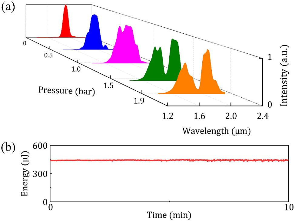
Figure 2 (a) Spectrum profiles measured by a near-infrared spectrometer at different argon pressures; (b) energy stability of the output laser after the HCF system.
The spectrum of the 1.8 μm laser pulse is wide enough after the HCF. To obtain an ultra-broadband SHG spectrum, we used cascaded crystals to achieve phase-matching at 1.8 and 2.0 μm at the same time. We measured the SHG spectra with one single crystal and cascaded crystals, respectively, and the results are shown in Figure 3. It can be seen that the 0.3 mm BBO crystal with an angle of 20.2º is more efficient in doubling the frequency of 1.8 μm, and thus pulses with a central wavelength of about 910 nm were observed. The output energy is 100 μJ, corresponding to the efficiency of 25.6%. The 0.8 mm BBO crystal with an angle of 21.0º is more efficient in doubling the frequency of 2.0 μm, and pulses with a central wavelength of about 1000 nm were observed. The output energy is 96 μJ, corresponding to the efficiency of 24.6%. Two BBO crystals with different thickness are used to ensure that the different parts of the SHG spectrum have a small intensity difference. Although the spectrum has a pedestal at about 700 nm in the shorter wavelength range with one single crystal, the energy of this part is too weak and it will be further reduced after the stretcher; thus, the whole spectrum will be significantly narrowed, which is not conducive to the amplification of the seed source in the following OPCPA system. Finally, we can see that the spectrum appears to be broader with optimized phase-matching, a broad spectrum with full width of more than 300 nm is obtained, and higher SHG efficiency is also guaranteed. The total output energy is 150 μJ, corresponding to the efficiency of 38.5%. We observed no interference at the spectral overlap in the experiment.
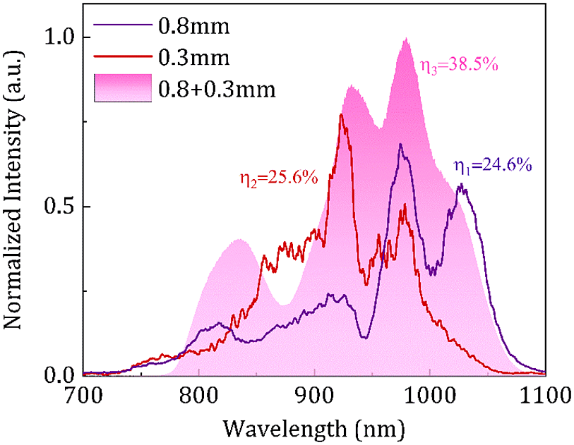
Figure 3 The SHG spectra with one single crystal and cascaded crystals.
We also measured the pulse duration of the output 910 nm using a Wizzler device (Fastlite, Inc.). After dispersion is compensated by a pair of fused silica wedges, the measured pulse duration is 9.6 fs at full width at half-maximum (FWHM) and the calculated Fourier transform limit (FTL) pulse duration is 9.0 fs (Figure 4(b)). The retrieved spectrum of the Wizzler device in Figure 4(a) matches the real spectrum from the spectrometer very well and the phase is flat. The cutoff of the spectrum measured by the Wizzler device at the long-wavelength edge is due to the limited measuring range of the instrument; there is almost no response with wavelengths longer than approximately 1030 nm.
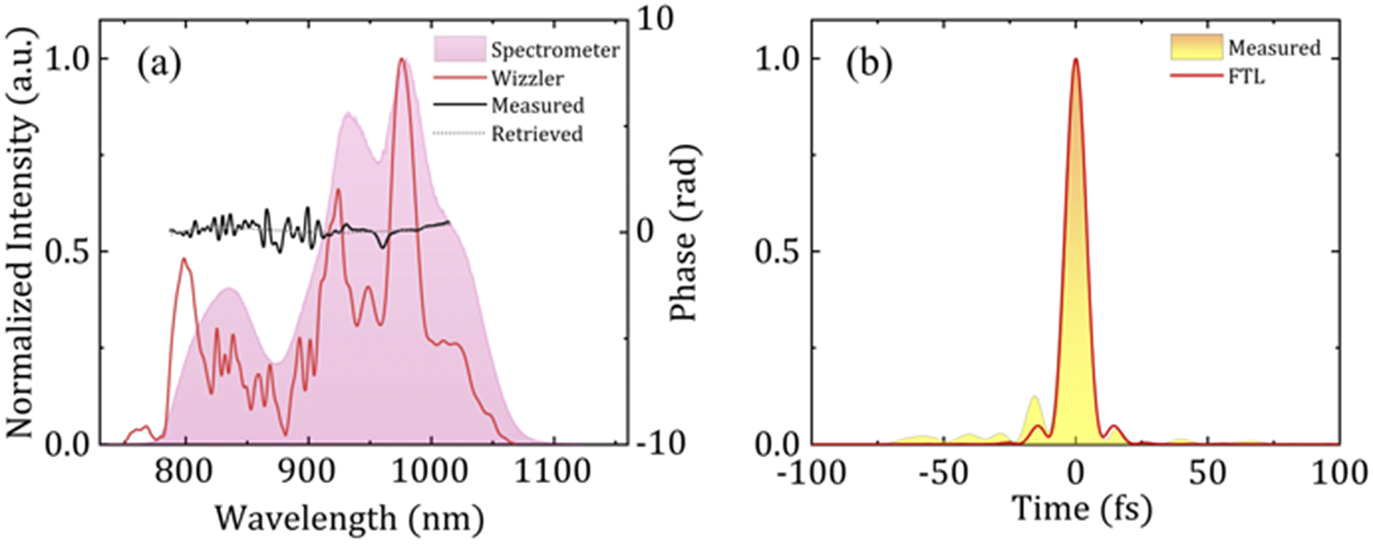
Figure 4 (a) Spectra and spectral phase of the 910 nm laser: spectrum (pink filled) with a fiber spectrometer, spectrum (red solid) with a Wizzler device, measured spectral phase (black solid) and retrieved spectral phase (black dot). (b) Measured (golden filled) and FTL (red solid) pulse duration of the 910 nm pulse.
Benefitting from the saturate effect in the SHG process, the output pulses have an excellent energy stability and the fluctuation of the pulse energy was measured to be 0.8% (RMS) over a 20 min recording with 10 shots per second (see Figure 5(a)). This laser intensity noise is mainly due to fluctuations of the OPA and environmental perturbations. In addition, the spectral stability was also measured over 60 min. A spectrum was collected every 10 s and the integral time was 100 ms, so each spectrum was an integrated spectrum of 100 pulses. As shown in Figure 5(b), the spectra remain stable, which guarantees the stable operation of the laser in the future. The near-field and far-field beam profiles of the 910 nm beam are also measured with a CCD (SP90421, Ophir), as shown in Figures 1(c) and 1(d), and they all maintain very good Gaussian spot shapes.
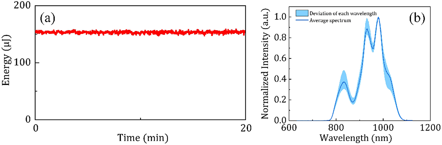
Figure 5 (a) Energy stability of the 910 nm laser; (b) spectrum stability of the 910 nm laser.
Furthermore, due to the cascaded crystals structure, the temporal contrast is greatly enhanced, which is significant for its application in ultra-intense and ultrashort laser systems. The temporal contrasts of both 800 nm Ti:sapphire CPA laser pulses (the initial pulse) and 910 nm output pulses (the cleaned pulse) were measured using two commercial third-order cross-correlators (Amplitude Technologies, Sequoia 800 nm and Sequoia 910 nm); the background noise of these two lasers is slightly different, where the noise of the customized instrument for 910 nm is higher than that for 800 nm. In the OPA, for the idler pulse (1.8 μm) generated from the third OPA, its pulse contrast can be increased to the quadratic times of the initial pulse[ Reference Shao, Li, Peng, Wang, Qian, Leng and Li12]. The SHG also utilizes a second-order nonlinear effect, which theoretically enables the square of the temporal contrast again. In theoretical calculation, the temporal contrast can be enhanced by a power of four due to the three-stage OPA and the cascaded SHG processes. As can be seen in Figure 6(a), the temporal contrast of the Ti:sapphire CPA laser was measured. We blocked the pulses at –250 ps to measure the background noise, which was below 10–11. The results show that the input 800 nm laser temporal contrast is 108, while the cleaned 910 nm laser temporal contrast is approaching 1011. The pulse contrast is improved by almost three orders of magnitude compared to the Ti:sapphire CPA laser. However, it can be seen that the bottom of the noise of the 910 nm laser is very flat, which indicates that this background noise has reached the detection limit of the measurement device under this energy level. Due to weak pulse energy, the actual contrast cannot be accurately measured. However, to test the temporal contrast of the laser seed, we injected this seed into a one-stage OPCPA system, where the amplified laser had 10 mJ energy, and we also measured the temporal contrast (Figure 6(b)). From the figure we can see that the contrast of the amplified pulse can reach 1012, which indicates the real temporal contrast of the broadband 910 nm laser seed should be better than 1012. The pre- and post-pulses labeled A and B in Figure 6(a) are located at –20 and +20 ps, respectively. The intensities of A and B show a squared relationship, so that pulse A is a pseudo pulse that is caused by pulse B due to third-order autocorrelation measurement. What is more, the pedestal in Figure 6(b) is mainly caused by spectral phase noise in the stretcher. The post-pulses usually do not propagate in the exact same direction as the main pulse and will be separated from the main pulse after stretching and propagating, so the spikes in Figure 6(a) are no longer detectable, which is universal in OPCPA and CPA systems[ Reference Dorrer and Bromage27].

Figure 6 (a) Third-order correlation curves of the initial pulse (black) and the 910 nm pulse (red); (b) third-order correlation curve of the laser pulse after a one-stage OPCPA system.
4 Conclusion
In summary, an ultra-broadband high temporal contrast laser source with 910 nm central wavelength and 1 kHz pulse repetition rate has been demonstrated, delivering a train of 150 μJ, sub-10 fs pulses with good energy stability and spectral stability. The spectrum of 1.8 μm laser pulses is broadened with near 1 μm full bandwidth by employing an argon gas-filled HCF. The output energy of the HCF system is 390 μJ and the corresponding transmittance is 57%. Furthermore, with a cascaded crystals-based SHG process, 910 nm laser pulses can be efficiently generated, which have remarkable qualities of over 300 nm spectral width, 9.6 fs pulse duration, more than 1012 temporal contrast and 0.8% (RMS) energy stability. This ultra-broadband, high contrast and stable ultrashort laser has great application potential to be the seed source for ultra-intense ultrashort lasers, especially for DKDP-based 100 PW OPCPA lasers.
Acknowledgements
This work was supported by the National Key R&D Program of China (2017YFE0123700); the Strategic Priority Research Program of the Chinese Academy of Sciences (XDB1603); the National Natural Science Foundation of China (61925507, 62075227, 12004402, 61635012); the Program of Shanghai Academic/Technology Research Leader (18XD1404200); the Shanghai Municipal Science and Technology Major Project (2017SHZDZX02); and the Youth Innovation Promotion Association CAS (2020248).


 Open access