


1 Introduction
Narrow-line-width pulsed solid-state lasers in the 2 μm eye-safe spectral region are usually used as the lidar emitter in coherent Doppler lidars for wind field measurement or in differential absorption lidars (DIALs) for monitoring the concentrations of gases such as CO2 and H2O[ Reference Dai, Ju, Duan, Shen, Yao and Wang 1 – Reference Wang, Gao, Na, Zhang, Ye and Gao 4 ]. A lidar configuration requires an emitter with high energy to increase the detection range, a long pulse width to improve the spectrum resolution and a narrow line width to enhance the spectral purity[ Reference Dai, Ju, Yao, Shen, Wang and Wang 5 ]. A critical technique for obtaining a narrow-line-width pulsed laser is the injection of a single-frequency continuous-wave (CW) laser into a Q-switched slave laser[ Reference Koch, Deyst and Storm 6 , Reference Henderson, Suni, Hale, Hannon, Magee, Bruns and Yuen 7 ]. In addition, there are two ways to obtain a long pulse width: one is to increase the cavity length of the Q-switched slave laser; and the other is to ensure that the slave laser operates at a lower energy. Increasing the cavity length, however, leads to difficulties with the cavity design, a complex structure and a large laser volume. Compared with a longer resonator, it is an effective approach for realizing a pulsed laser with narrow line width, long pulse width and high energy, by making the Q-switched slave laser operate at a lower energy and then increasing the output energy through an amplifier system.
A Ho-doped single-frequency solid-state laser is a significant means for obtaining a 2 μm narrow-line-width laser that benefits from an insensitivity to temperature, low quantum defects and low upconversion losses[ Reference Budni, Ibach, Setzler, Gustafson, Castro and Chicklis 8 , Reference Zhang, Gao, Wang, Na, Gao, Zhang and Huang 9 ]. Anisotropic holmium-doped yttrium lithium fluoride (Ho:YLF) crystals have the capability to generate high energy lasers due to the combination of a high emission cross-section and a long upper-level lifetime (14 ms) for Ho3+ transition[ Reference Dergachev, Moulton and Drake 10 , Reference Koen, Bolling, Straus, Schellhorn, Jacobs and Esser 11 ]. More importantly, the output spectrum of a Ho:YLF laser can be tuned over many CO2 characteristic absorption lines[ Reference Bai, Yu, Petros, Petzar, Trieu, Lee and Singh 12 – Reference Joly, Gibert, Grouiez, Grossel, Parvitte, Durry and Zéninari 14 ]. The most commonly used CO2 absorption line around the 2050 nm emission peak of Ho:YLF crystal is 2050.967 nm. In 2009, Bai et al. proposed a single-frequency injection-seeded Q-switched Ho:YLF laser for CO2 measurement[ Reference Bai, Yu, Petzar, Petros, Chen, Trieu, Lee and Singh 15 ]. With a pulse repetition frequency (PRF) of 1.25 kHz, the output energy and pulse width of a single-frequency Ho:YLF laser were 5.5 mJ and 50 ns, respectively. The online wavelength was locked to the R30 CO2 absorption line at 2050.967 nm, and the offline wavelength was 2051.023 nm. In 2014, Gibert et al. reported a single-frequency two-wavelength pulsed Ho:YLF laser for CO2 DIAL applications[ Reference Gibert, Edouart, Cénac and Mounier 16 ]. At a PRF of 2 kHz, a maximum single-frequency output energy of 13.5 mJ was obtained, with a pulse width of 42 ns. The online wavelength was locked to the R30 CO2 absorption line at 2050.967 nm. Near the 2064 nm emission peak of Ho:YLF crystal (π- or σ-polarization), however, the P12 CO2 absorption line at 2064.414 nm was another choice because it has higher absorption intensity, and there is no absorption of other trace gases. Therefore, the single-frequency pulsed laser around 2064 nm based on Ho:YLF crystal is an extremely promising emitter for DIAL systems.
In this paper we propose a single-frequency single-pass Ho:YLF amplifier around the P12 CO2 absorption line. The output characteristics of the Ho:YLF amplifier under free-running and single-frequency operation were compared for the first time. An output energy of 24.2 mJ with a pulse width of 250 ns at a PRF of 100 Hz was obtained. The energy stability during 30 min was improved from 3.8% to 1% when the single-frequency pulsed Ho:YLF laser was amplified. The pulse build-up time of the Ho:YLF amplifier under single-frequency operation was 0.37 μs shorter than that of free-running operation. The line width of the single-frequency pulsed Ho:YLF amplifier measured by a heterodyne technique was 2.81 MHz.
2 Experiment
The experimental setup of the single-frequency Q-switched Ho:YLF ring laser and the single-pass amplifier is shown in Figure 1. The Q-switched Ho:YLF ring laser comprising five mirrors was pumped by a 25 W Tm-doped all-fiber laser, and injected with a single-frequency CW Ho:YLF laser at the P12 CO2 absorption line of 2064.414 nm. To achieve a long pulse-width output, the total physical length of the ring laser was 2.53 m. The length-to-width ratio of the ring laser was 6:1, which indicated that the ring laser had a relatively small volume. See Wu et al.[ Reference Wu, Wang, Dai, Ju, Yao and Wang 17 ] and Wang et al.[ Reference Wang, Dai, Liu, Ju and Yao 18 ] for more details about the single-frequency CW Ho:YLF laser and the pulsed Ho:YLF ring laser. Two laseroutput directions were obtained when the Ho:YLF ring laser was under free-running operation. In contrast, the ring laser realized unidirectional operation to achieve single-frequency pulsed laser output when it was injected by the single-frequency CW Ho:YLF laser. For convenience, both the single-frequency CW Ho:YLF laser and the ring laser are considered as the seed laser.
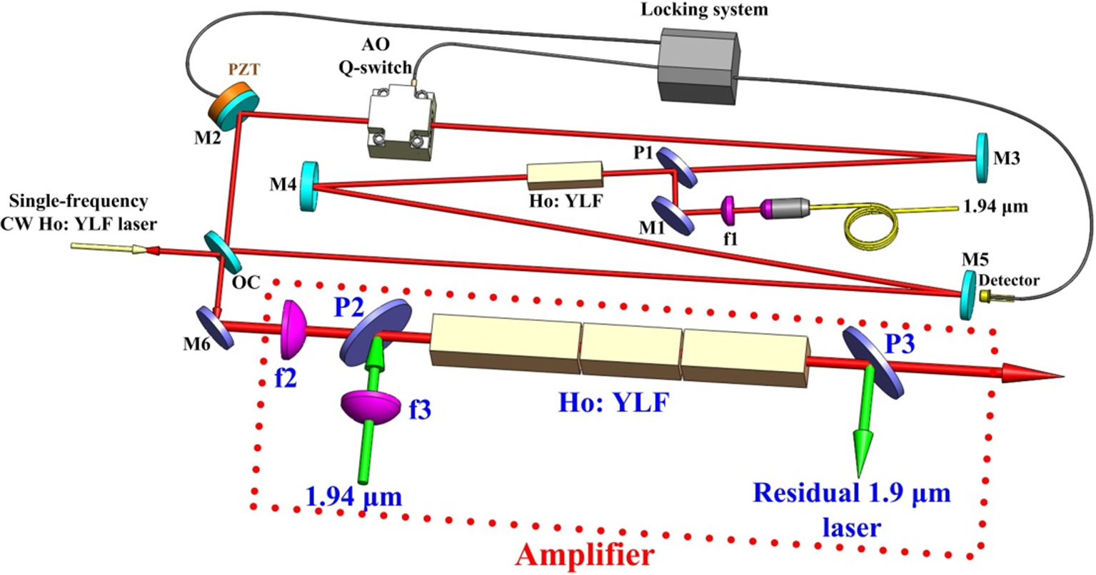
Figure 1 Experimental setup of the single-frequency pulsed Ho:YLF ring laser and the single-pass amplifier.
The single-pass amplifier with three adjacent Ho:YLF crystals was end-pumped by an ellipse-polarization Tm-doped fiber laser with a central wavelength of 1940 nm. At a total pump power of 33.9 W, the powers of p-polarized and s-polarized light were 17.6 W and 16.3 W, respectively. The pump beam was focused by the spherical positive lens f3 with a focal length of 200 mm. The waist radii of the pump beam in the front face of the first Ho:YLF crystal were 0.34 mm in the horizontal position and 0.44 mm in the vertical position. The single-frequency pulsed Ho:YLF seed laser beam was focused by the spherical positive lens f2 with a focal length of 240 mm, and the waist radius was 0.48 mm in the center of the first Ho:YLF crystal. M6 was a coated plane mirror, with high reflectivity from 1.94 μm to 2.06 μm. P2 and P3 were 45° polarizers with high reflectivity at 1.9 μm, high transmission for 2.06 μm p-polarized light and high reflectivity for 2.06 μm s-polarized light. Three a-cut Ho:YLF crystals with the dimensions 5 mm × 4 mm × 60 mm, 5 mm × 4 mm × 30 mm and 4 mm × 5 mm × 40 mm were doped with 0.5 at.% Ho3+, wrapped with indium foil, and mounted on a copper heat sink. Both end faces of the three crystals were coated with 1.9 μm and 2.1 μm antireflection (AR) coating. The temperature of the three Ho:YLF crystals was controlled at 18 ± 0.1°C by circulating water. The first two Ho:YLF crystals were oriented with their c-axes horizontal and the last Ho:YLF crystal was oriented with its c-axis vertical, so that the p-polarized pump laser through the first two crystals and the s-polarized pump laser through the last crystal had a low loss due to the polarization absorption characteristics of the Ho:YLF crystal. Under a pump power of 33.9 W, the absorption efficiencies of p-polarized and s-polarized pump light through the first Ho:YLF crystal were 53% and 27%, respectively. To further increase the absorption efficiency of p-polarized light, the second Ho:YLF crystal was used. The corresponding absorption efficiencies of p-polarized and s-polarized pump light were 70.1% and 41.7%, respectively. In order to increase the absorption efficiency of s-polarized light, the last Ho:YLF crystal was employed. The corresponding absorption efficiencies of p-polarized and s-polarized pump light were 75.7% and 72.8%, respectively, resulting in a total absorption efficiency of 74.3%.
3 Results and discussion
The output energy of the single-frequency pulsed Ho:YLF seed laser at a PRF of 100 Hz measured by an energy meter (Coherent, J-10MB-HE) is illustrated in Figure 2(a). Under a pump power of 9.68 W, an output energy of 2.6 mJ was obtained. The wavelength from the pulsed output spectrum monitored by an optical spectrum analyzer (Yokogawa, AQ6375B) was centered at 2064.416 nm, which was around the P12 CO2 absorption line, as shown in the inset in Figure 2(a). The pulse width of the single-frequency pulsed Ho:YLF seed laser recorded by an InGaAs detector and line width measured by a heterodyne technique as functions of the seed pump power are shown in Figure 2(b). A pulse width of 255.2 ns and a line width of 2.79 MHz were achieved at a seed pump power of 9.68 W.

Figure 2 Output characters of the single-frequency pulsed Ho:YLF seed laser. (a) Output energy versus pump power; (b) pulse width and line width versus pump power.
The output energy of the single-frequency single-pass pulsed Ho:YLF amplifier at different seed energies is shown in Figure 3. It can be seen that the output energy increases with pump power under the same seed energy. At the incident pump power of 33.9 W and a seed energy of 2.6 mJ, the output energy of the single-frequency Ho:YLF amplifier reached 24.2 mJ, with a pulse width of 250 ns at a PRF at 100 Hz, resulting in a gain of 9.69 dB. The pulse width was narrower after amplification because the population inversion was consumed at the pulse leading edge, and a smaller gain was obtained at the pulse trailing edge.

Figure 3 Output energy of the single-frequency Ho:YLF amplifier versus pump power.
The energy fluctuations of the pulsed Ho:YLF amplifier under free-running and single-frequency operation were investigated, as shown in Figure 4. Under free-running operation, the standard deviation of the amplifier energy during 30 min was 0.37 mJ, corresponding to an energy stability of 3.8%, which was calculated by dividing the standard deviation by the mean. When the single-frequency seed laser was amplified, the standard deviation of the amplifier energy during 30 min was 0.21 mJ, corresponding to an energy stability of 1%. The energy stability was improved after the single-frequency seed laser was amplified because the gain competition effect from two directions of the Ho:YLF ring laser was eliminated by the injection of the single-frequency CW Ho:YLF laser. The amplifier output energy under free-running operation was approximately half that of single-frequency operation due to the bidirectional output of the ring laser.

Figure 4 Energy stability of the Ho:YLF amplifier under free-running and single-frequency operation.
The pulse build-up time of the Ho:YLF amplifier under free-running and single-frequency operation is shown in Figure 5. At a PRF of 100 Hz and a pump power for the Ho:YLF seed laser of 9.68 W, the pulse build-up time of the Ho:YLF amplifier was 2.58 μs under free-running operation, and 2.21 μs under single-frequency operation. The phenomenon of a shorter pulse build-up time under single-frequency operation was mainly caused by the upper level population of Ho3+ being excited by the single-frequency CW Ho:YLF laser injection; the stimulated radiation then became dominant. Therefore, pulse establishment was completed ahead of time compared to the spontaneous radiation of the pulsed Ho:YLF laser under free-runningoperation.

Figure 5 Pulse build-up time of the Ho:YLF amplifier. (a) Under free-running operation; (b) under single-frequency operation.
The temporal pulse shapes of the Ho:YLF amplifier were measured with a high-speed InGaAs detector (1 GHz bandwidth) connected to a digital oscilloscope (1 GHz bandwidth) at a PRF of 100 Hz; and the fast Fourier transform (FFT) curves of the temporal shapes were calculated, as shown in Figure 6. The emergence of mode beating under free-running operation as shown in Figure 6(a) was due to the multi-longitudinal-mode operation of the ring laser. The free spectrum range (FSR) of 116 MHz was obtained from the FFT curve, which was in correspondence to the 2.53 m ring laser. Compared with Figure 6(a), the temporal pulse shape of the Ho:YLF amplifier at 24.2 mJ in Figure 6(b) was relatively smooth, and there were no mode beating spikes from the FFT curve due to the single-frequency operation of the ring laser.
The pulsed spectrum of the Ho:YLF amplifier under single-frequency operation was measured by a heterodyne technique. The frequency of the CW single-frequency Ho:YLF laser was shifted by an 80 MHz acousto-optic modulator (AOM). The frequency-shifted CW Ho:YLF laser and a small part of the single-frequency pulsed Ho:YLF laser from the amplifier were then mixed into a fiber combiner for measuring the beating signal. The beating signal recorded by an InGaAs detector and a digital oscilloscope is shown in Figure 7(a). The line width of 2.81 MHz was estimated from the pulsed spectrum after an FFT operation upon the beating signal, as shown in Figure 7(b).

Figure 6 Temporal shapes and FFT curves for the Ho:YLF amplifier. (a) Free-running operation; (b) single-frequency operation.

Figure 7 Laser properties of the single-frequency Ho:YLF amplifier. (a) Beating signals; (b) fast Fourier transform (FFT) spectrum of the beating signals.
4 Conclusions
We compared a single-pass Ho:YLF amplifier under free-running and single-frequency operation. The output energy of 24.2 mJ with a pulse width of 250 ns at a PRF of 100 Hz was obtained. The output spectrum of the single-frequency pulsed Ho:YLF amplifier was around the P12 CO2 absorption line. The energy stability during 30 min was improved from 3.8% to 1% after the single-frequency pulsed Ho:YLF laser was amplified. The pulse build-up time of the Ho:YLF amplifier under single-frequency operation was 0.37 μs shorter than that under free-running operation. Compared with free-running operation, the absence of mode beating of the temporal pulse shape was due to the single-frequency operation of the Ho:YLF amplifier. The line width of the single-frequency pulsed Ho:YLF amplifier measured by a heterodyne technique was 2.81 MHz.
Acknowledgements
This work was supported by the National Natural Science Foundation of China (No. 51572053).


 Open access