


1 Introduction
The next generation of laser facilities will offer high-energy pulses as well as high repetition rates, enabling ‘real-world’, high-throughput applications and a wide range of science that requires the acquisition of high volumes of data. Such applications include advanced materials processing and laser shock peening[Reference Peyre and Fabbro1], high energy density (HED) physics studies[Reference Drake2] and pumping of ultra-high-intensity fs petawatt-class lasers to generate secondary radiation (X-rays and  $\unicode[STIX]{x03B3}$-rays) and particle (electrons, protons and muon) sources[Reference Perry, Sefcik, Cowan, Hatchett, Hunt, Moran, Pennington, Snavely and Wilks3, Reference Tajima and Dawson4].
The Center for Advanced Laser Technology and Applications (CALTA) at STFC’s Central Laser Facility (CLF) is a pioneer of ‘DiPOLE’ multi-slab, cryogenic gas cooled Yb:YAG amplifier technology. In 2015, a single-stage prototype cryogenic gas cooled amplifier, called the DiPOLE system, achieved an output in excess of 10 J at 10 Hz, with an optical-to-optical efficiency of 22%[Reference Banerjee, Ertel, Mason, Phillips, De Vido, Smith, Butcher, Hernandez-Gomez, Greenhalgh and Collier5]. Further, energy scaling up to 100 J at 10 Hz was reported for the first time in a two-stage cryo-amplifier[Reference Mason, Divoký, Ertel, Pilař, Butcher, Hanuš, Banerjee, Phillips, Smith, De Vido, Lucianetti, Hernandez-Gomez, Edwards, Mocek and Collier6], delivered to the HiLASE facility[Reference Novák, Miura, Smrž, Chyla, Nagisetty, Mužík, Linnemann, Turčičová, Jambunathan, Slezák, SawickaChyla, Pilař, Bonora, Divoký, Měsíček, Pranovich, Sikocinski, Huynh, Severová, Navrátil, Vojna, Horáčková, Mann, Lucianetti, Endo, Rostohar and Mocek7] at Dolni Brezany in the Czech Republic.
In this paper, we report the scaling up of DiPOLE technology to a pulse energy of 150 J at 1 Hz. To the best of our knowledge, this is the highest energy achieved by a diode-pumped solid-state laser. These results were obtained during the development of a two-stage cryogenic gas cooled amplifier, called D100X, to be supplied to the European XFEL facility[Reference Vagovič, Sato, Mikeš, Mills, Graceffa, Mattsson, Villanueva-Perez, Ershov, Faragó, Uličný, Kirkwood, Letrun, Mokso, Zdora, Olbinado, Rack, Baumbach, Schulz, Meents, Chapman and Mancuso8] for use in HED science experiments. The nominal operating condition for the laser is 100 J, 10 ns at 10 Hz with advanced temporal pulse shaping capabilities to enable low entropy compression of materials.
2 Setup and results
Figure 1 shows the three-dimensional (3D) model of the D100X laser system divided into three main components, namely, front end (FE), first-stage cryo-amplifier (MA1) and second-stage cryo-amplifier (MA2). Design details of each amplifier stage have been reported previously[Reference Mason, Banerjee, Ertel, Phillips, Butcher, Smith, De Vido, Tomlinson, Chekhlov, Shaikh, Blake, Holligan, Divoky, Pilar, Hernandez-Gomez, Greenhalgh and Collier9]. As the amplifiers (MA1 and MA2) require cooling down to cryogenic temperatures, the system requires about 2.5 h of cool-down time from room temperature before the setup is ready for high-energy amplification. In the 10 Hz operating mode, a pulse energy of 105 J (1.05 kW average power) was obtained when MA2 was seeded by 6 J, 10 ns pulses from MA1. The helium gas flow, temperature and diode pump pulse duration for MA2 were maintained at  $180~\text{g}/\text{s}$, 140 K and $650~\unicode[STIX]{x03BC}\text{s}$, respectively. The inset in Figure 1 shows the far-field profile at kW-level operation. For a 3 m focal length lens, the focal spot size was $87.9~\unicode[STIX]{x03BC}\text{m}$ ( $x$-axis) by $105.4~\unicode[STIX]{x03BC}\text{m}$ ( $y$-axis). This is 1.6 and 2.0 times the diffraction limit for a square super-Gaussian (SG) beam, and this corresponds to 50% energy encircled in a $32~\unicode[STIX]{x03BC}\text{m}$ radius.

Figure 1. 3D model of D100X laser showing FE  $=$ front end; BT $=$ beam transport; PA $=$ room-temperature pre-amplifier (1 $=$ Yb:CaF2 regenerative, 2 $=$ Yb:YAG multi-pass); MA $=$ main cryogenic amplifier (1 $=$ stage 1, 2 $=$ stage 2); CGC $=$ cryogenic gas coolers; D $=$ 940 nm diode pumps (1 & 2 for MA-1, 3 & 4 for MA-2). The inset shows the far-field image recorded at 105 J, 10 Hz operation.

Figure 2. (a) Example of automatic pulse shaping capability of the D100X laser for achieving a flat-top temporal profile at ${>}$75 J, 10 Hz operation;(b) long-term stability over 6 h at 10 Hz.
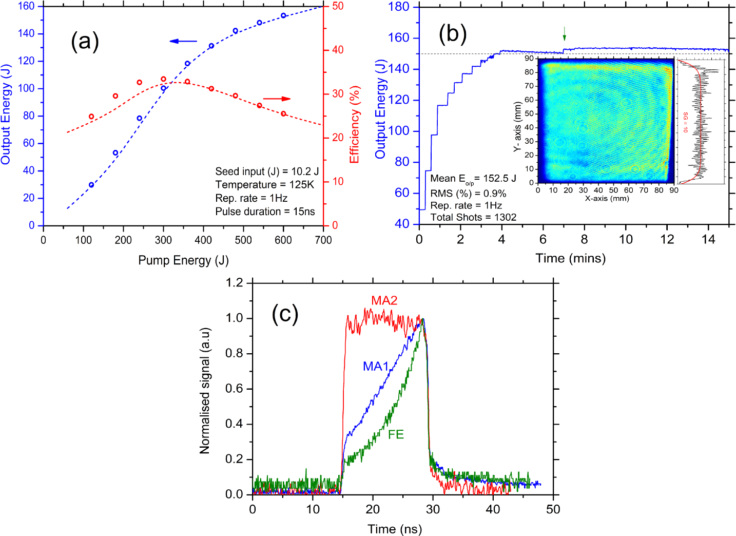
Figure 3. (a) Output energetics, experimentally measured (circle) and numerically calculated (dotted lines); (b) long-term operation at 150 J, 1 Hz, and the inset shows the near-field profile at 150 J, 1 Hz operation; (c) temporal profile of the front end (FE), main-amplifier 1 (MA1) and main-amplifier 2 (MA2) during 150 J, 1 Hz operation.
As precise control over the temporal profile is important for achieving efficient densification of materials in HED experiments, an automated pulse shaping capability was incorporated into the D100X laser system. A typical example is shown in Figure 2(a), where the desired temporal profile was a 10 ns flat-top output. An initial temporal profile was created using an arbitrary waveform generator (AWG), and fed through an amplifier chain, which modified the temporal shape depending on the amplification at different stages. The output temporal shape was then fed to the control software, which calculates a new profile based on the difference between the desired and present temporal shapes. The new profile was fed back to the AWG, and the process was repeated till the desired temporal profile was obtained. Figure 2(a) shows an example of automatic pulse shaping at  ${>}$75 J, 10 Hz operation, where four iterations of the shaping cycles were required to achieve a flat-top temporal profile. Figure 2(b) shows the long-term energy stability of the laser for 6 h operation ( $2\times 10^{5}$ shots) with an RMS value of 0.8%.
To explore the energy scalability of the system, the seed input and pulse duration from MA1 were increased to 10 J and 15 ns, respectively, at 1 Hz. The MA2 temperature was decreased to 125 K and the diode pump pulse duration was increased to 1 ms. Output energetics for the experiments are shown in Figure 3(a) with a conversion efficiency of 26% measured for 150 J output. It should be noted that a peak efficiency of  ${\sim}$34% was measured for an output energy near 100 J. Figure 3(b) shows the long-term operation of the system at 150 J, 1 Hz; the near-field (NF) profile at 150 J, 1 Hz is also shown. An increase in the repetition rate to 10 Hz at 150 J will require damage-resilient optics (for the increase in fluence) and higher gas flow (for the increase in heat load). The circular and vertical features seen in the NF profile are caused by the interference effect within the neutral density filters used in the diagnostic channel. These fringes are not visible for a profile taken on a light sensitive paper. An SG profile of order 10 fits the $y$-axis cross-section of the NF. Figure 3(c) shows the temporal profiles of the FE, main-amplifier 1 (MA1) and main-amplifier 2 (MA2) during the 150 J, 1 Hz operation.
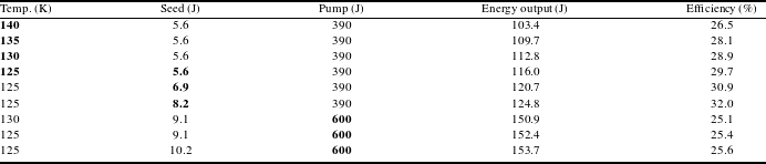
The dependence of laser performance on the MA2 temperature, diode pump input energy and MA1 seed energy was studied further with the results tabulated in Table 1. Note that efficiency improves with a reduction of amplifier temperature. A similar trend is observed for an increase in seed energy (MA1) for a fixed temperature (MA2). Although the extracted energy increases to 150 J at 600 J pump input (1 ms duration), the efficiency reduces and remains constant even with an increase of the seed input. This result indicates that an optimum combination of temperature, seed and pump input is required to extract the maximum energy with best efficiency.
Table 1. D100X laser system performance at different temperatures, seed and pump inputs.
3 Conclusion
In summary, we have demonstrated 150 J, 1 Hz nanosecond pulsed output from a cryogenic gas cooled, multi-slab Yb:YAG laser. The system has now exceeded its design specification and is currently being installed in the laser laboratory at XFEL by a joint team of XFEL and CLF engineers and scientists.


 Open access