


1 Introduction
Owing to a hierarchical, nanoporous microstructure and unique properties, aerogel is different from ordinary materials and even considered to be a new state of matter[Reference Du, Zhou, Zhang and Shen1]. Silica aerogel, first prepared in 1931, has aroused interest in many different fields especially for aerospace applications[Reference Bheekhun, Talib and Hassan2]. It has been demonstrated that silica aerogel can capture particles with speeds up to 10 km/s relatively intact in the laboratory[Reference Tsou, Brownlee, Laurance, Hrubesh and Albee3, Reference Kearsley, Burchell, Price, Cole, Wozniakiewicz, Ishii, Bradley, Fries and Foster4]. In addition, silica aerogel capture cells had been deployed in space missions[Reference Kearsley, Burchell, Price, Cole, Wozniakiewicz, Ishii, Bradley, Fries and Foster4, Reference Burchell, Graham and Kearsley5]. On the Mir space station, silica aerogels were exposed to and captured successfully hypervelocity particles from both man-made and natural sources[Reference Hörz, Zolensky, Bernhard, See and Warren6]. In the NASA Stardust mission[Reference Brownlee, Tsou, Anderson, Hanner, Newburn, Sekanina, Clark, Hörz, Zolensky and Kissel7], silica aerogels were used in the primary instrument to capture fine particles from both Comet 81P/Wild 2 and interstellar particle[Reference Jones8–Reference Burchell, Fairey, Wozniakiewicz, Brownlee, Hoerz, Kearsley, See, Tsou, Westphal, Green, Trigo-Rodriguez and Dominguez12]. Meanwhile, in the laser shock-loaded collection experiment, silica aerogels have been used as fragment collectors for many years[Reference Lee, Benedetti, Jeanloz, Celliers, Eggert, Hicks, Moon, Mackinnon, Da Silva, Bradley, Unites, Collins, Henry, Koenig, Benuzzi-Mounaix, Pasley and Neely13, Reference de Resseguier, Loison, Lescoute, Signor and Dragon14]. So far, silica aerogel has been proved as an ideal capture medium for space debris, interplanetary dust and shock-loaded fragments (highly transparent, low density, highly porous, etc.), which can capture the hypervelocity particles efficiently and nondestructively. In general, ground experiments for hypervelocity impact were conducted on the two-stage light-gas gun (LGG) and plasma gun (PG)[Reference Kitazawa, Fujiwara, Kadono, Imagawa, Okada and Uematsu15]. The transparent silica aerogel makes it easier to observe the captured particle and the entire penetration path of the projectile. Analysis of the captured particles can be done either in situ or after extraction[Reference Burchell, Graham and Kearsley5]. On the one hand, much research focusing on the captured particles and tracks has been performed. Hörz et al. [Reference Hörz, Bastien, Borg, Bradley, Bridges, Brownlee, Burchell, Chi, Cintala, Dai, Djouadi, Dominguez, Economou, Fairey, Floss, Franchi, Graham, Green, Heck, Hoppe, Huth, Ishii, Kearsley, Kissel, Leitner, Leroux, Marhas, Messenger, Schwandt, See, Snead, Stadermann, Stephan, Stroud, Teslich, Trigo-Rodriguez, Tuzzolino, Troadec, Tsou, Warren, Westphal, Wozniakiewicz, Wright and Zinner10] found that tracks formed at lower impact velocities were relatively slender compared with those observed in the shallow pits on the Mir station and the track length was not systematically correlated with the size of the projectile residues. Hörz et al. also showed the diverse aerogel track shapes created by impacts of cometary dust in the Stardust collector and classified that into three broad types (A, B, and C). Burchell et al. [Reference Burchell, Fairey, Wozniakiewicz, Brownlee, Hoerz, Kearsley, See, Tsou, Westphal, Green, Trigo-Rodriguez and Dominguez12] quantified typical limiting dimensions and found that there are various track parameters (including track shape, total length, and maximum width) measured in the Stardust mission. Kearsley et al. [Reference Kearsley, Burchell, Price, Cole, Wozniakiewicz, Ishii, Bradley, Fries and Foster4] considered the differences may be derived from the complex impactor behavior and aerogel response, so they carried out ground experiments with a diverse suite of projectile particles to demonstrate their hypothesis. It was confirmed that elongated and narrow type A tracks were generated by impacts of glasses and robust mineral grains, but with differing levels of abrasion and lateral branch creation[Reference Kearsley, Burchell, Price, Cole, Wozniakiewicz, Ishii, Bradley, Fries and Foster4, Reference Niimi, Kadono, Tsuchiyama, Okudaira, Hasegawa, Tabata, Watanabe, Yagishita, Machii, Nakamura, Uesugi, Takeuchi and Nakano16]. On the other hand, numerous modeling and experimental approaches were concluded to estimate the conditions of impact in aerogel. Simple track formation was explained by the theoretical models, which had largely agreed with many LGG shots of robust projectiles. In fact, in addition to the type A (straight path) tracks, track curvature was exhibited as the result of ground experiments in the available reports. The gently curving carrot-shaped tracks observed in aerogel were assigned as being due to the irregular shape of projectiles. This is closer to the actual situation whereby many items of space debris have irregular shapes. However, until now, there has been no complete understanding of the impact behaviors and typical track morphology of irregular particles. Thus, it is worthwhile to analyze track morphology of hypervelocity irregular grains in silica aerogel.
In this paper, the hypervelocity impact experiment was conducted on diverse density aerogel with robust irregular Al2O3 grains as the projectile. The tracks penetrated by projectiles were measured by optical imagery. Track morphologies and residues were carefully observed by video measuring machine (VMM), laser scanning confocal microscopy (LSCM), and optical coherence tomography (OCT). The classification and analysis of poses of residues have been studied to improve the understanding of the impact behaviors of irregular particles.
2 Experiment
2.1 Aerogel target
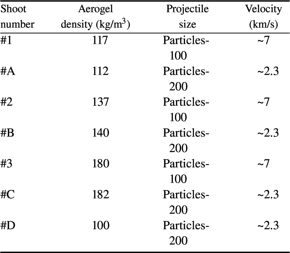
The SiO2 aerogel samples were obtained via a one-step sol-gel route and ethanol supercritical drying method. A silicon oxide precursor, tetramethyl orthosilicate (TMOS), was dissolved in methanol and hydrolyzed[Reference Rao, Pajonk and Parvathy17, Reference Rao, Pajonk and Parvathy18]. By using ammonia as a catalyst and methanol as a solvent, a series of varying density SiO2 aerogels were prepared. More transparent samples (#D) were obtained by a two-step method with acetonitrile and silica sol, following similar previous work[Reference Liu and Zhou19, Reference Tillotson and Hrubesh20]. All aerogel samples were monolithic, in the shape of 1.5–2.5-cm-long cylinder, 2.7–4.8 cm in diameter. The apparent density was determined by a weighing method. The impact targets were divided into two groups. Experimental conditions are listed in Table 1.
Table 1 List of experimental conditions.
2.2 Projectile materials
As is well known, alumina (Al2O3, density ~3.5 × 10³ kg/m3) is regarded as the main exhaust particle from solid rocket motors. In this paper, irregularly shaped Al2O3 grains were used as projectiles to simulate space debris (scanning electron microscopy (SEM) images are shown in Figure 1). Al2O3 grains of two different sizes were provided by the National Space Science Center (NSSC), Chinese Academy of Sciences (CAS), named as Particles-100 and Particles-200. Note that Particles-200 exhibits holes on the surface (marked in red in Figure 1(c)), which is similar to the real-life situation. Before the impact experiments, an ablator film was used to load the projectiles (Figure 1(b)), similar to the processes described by Best et al. Only a single projectile type is employed in the sabot of each shot.

Figure 1 SEM images of irregularly shaped Al2O3 grains of (a) Particles-100 and (c), (d) Particles-200 (with surface holes) used as projectiles in the PG experiment. (b) Al2O3 grains on Mylar film.
2.3 Launch facilities
The impact laboratory experiments were conducted by the PG of the plasma dynamic accelerator (PDA) of NSSC, CAS. The impact velocities covered by the two data sets were about 2.3 and 7 km/s, respectively. In the PG of PDA, irregularly shaped Al2O3 grains were adhered evenly to the Mylar film in a monolayer manner as far as possible (Figure 1(b)).
In the PDA[Reference Huang, Han, Li, Cai, Li, Zhang, Chen, Wang, Yang, Feng and Chin21], the hot plasma was produced by disruptive discharge, along with a strong current J and toroidal magnetic field B. Then the plasma was rapidly accelerated by a strong Ampere's force (J × B). This plasma then accelerated projectiles that were loaded on the Mylar film. The particle cloud was accelerated by the PG, then flew through the straight isolation tube with vacuum, and finally impacted on the aerogel targets. The device illustrated in Figure 2 is similar to that described by Kitazawa et al. [Reference Kitazawa, Fujiwara, Kadono, Imagawa, Okada and Uematsu15]. In addition, the vacuum degree of the vacuum chambers is lower than 6 × 10⁻³ Pa.
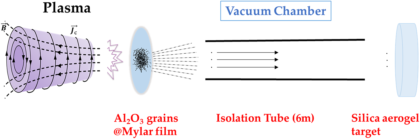
Figure 2 Schematic diagram of projectile flight in the PG.
The velocity of impactors was controlled by the capacitor discharge. One group of launch speed experiments (e.g., #1, #2, #3) was conducted and assumed to be at the same speed. An impact of vibration signal acquisition unit was placed on a sample stage without any aerogel target to measure the flight time of the particles. The speed was calculated from the flight time and flight distance (6 m). The calculated speed was the reference for the next several experiments in the same group with the same impact conditions (vacuum level, capacitance, voltage, etc.).
2.4 Imaging
Based on optical imagery, a VMM was employed to record the status of remaining particles and shape of tracks. Tracks in impacted aerogel targets were photographed on a glass or transparent plastic surface, with side or back lighting. The track lengths near the surface of the cylindrical rods for each experiment were carefully measured. It was evident that small projectile residual grains along the trunk were left at the terminus of each track.
In addition to confirming the detailed morphology of the track entrance, the track was observed vertically using LSCM. The images were exhibited with high resolution and three dimensions.
In addition, OCT (Hangzhou Regenovo Biotechnology Co., Ltd, China) was conducted to measure the details of some tracks. OCT was developed for noninvasive cross-sectional imaging in biological systems[Reference Huang, Swanson, Lin, Schuman, Stinson, Chang, Hee, Flotte, Gregory, Puliafito and Fujimoto22]. The technique uses low-coherence interferometry to produce a two-dimensional image of optical scattering from internal tissue microstructures[Reference Wang, Povazay, Chen, Hofer, Drexler and Guggenheim23, Reference Shi, Dai, Wang, Ding, Rao and Zhang24]. In this paper, the imaging system was used to observe impact tracks, based around a swept-source laser with a center wavelength of 1310 nm. The principle of measuring is analogous to ultrasonic pulse-echo imaging. Photographs were taken of the impacted surface and the lateral surface of the cylinder.
Furthermore, the morphology of silica aerogel as capture media, Al2O3 grains as projectiles, details of the entrance hole and tracks were observed by SEM (Philips-XL30FEG).
3 Results
3.1 Impact tests
Seven impact experiments were successfully conducted at the PG of PDA, details are listed in Table 1. Two sizes of projectiles were captured primarily in two groups of the seven aerogel samples. Filtered by isolation tube, scattering hypervelocity particles were shot by plasma and vertically impacted on aerogel targets with velocities of 2.3 and 7 km/s (Figure 2).
The Stardust track shapes could be classified into three types[Reference Hörz, Bastien, Borg, Bradley, Bridges, Brownlee, Burchell, Chi, Cintala, Dai, Djouadi, Dominguez, Economou, Fairey, Floss, Franchi, Graham, Green, Heck, Hoppe, Huth, Ishii, Kearsley, Kissel, Leitner, Leroux, Marhas, Messenger, Schwandt, See, Snead, Stadermann, Stephan, Stroud, Teslich, Trigo-Rodriguez, Tuzzolino, Troadec, Tsou, Warren, Westphal, Wozniakiewicz, Wright and Zinner10] and quantified according to typical limiting dimensions[Reference Burchell, Fairey, Wozniakiewicz, Brownlee, Hoerz, Kearsley, See, Tsou, Westphal, Green, Trigo-Rodriguez and Dominguez12]. This research method is widely recognized by researchers[Reference Kearsley, Burchell, Price, Cole, Wozniakiewicz, Ishii, Bradley, Fries and Foster4]. The impact tracks were close to type A but without stylus in impact experiments. Moreover, there were almost no type B (an initial bulbous portion with one or more styli far from the surface) or type C (broad and bulbous with no elongate styli) tracks. In other words, the tracks in experiments only exhibited the ‘spikes’ part of type A. The bow shock was produced while the projectile was proceeding through the aerogel. Periodic cracks growing from the side of the cavity were also observed similar to the results of Niimi et al.’s work[Reference Niimi, Kadono, Arakawa, Yasui, Dohi, Nakamura, Iida and Tsuchiyama25].
3.2 Experimental results
As a highly transparent capture medium, silica aerogel transmits most visible light, but scatters the shorter wavelengths strongly, making it appear blue[Reference Barrett, Zolensky, Horz, Lindstrom and Gibson26] (Figure 3(a)). However, after the impact experiment, it could be clearly observed that the impacting surface was covered by a gray substance (Figure 3(b)).
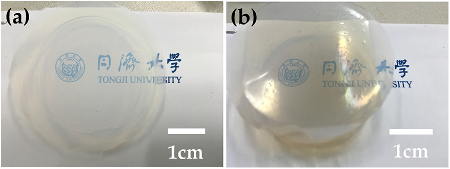
Figure 3 Contrast figures for the landing surface of the targets (a) before and (b) after impact.
The projectile landing area and the square cover gray area are determined by the open window of the specimen holder against the isolation tube. The plasma temperature is as high as several thousand Kelvin[Reference Best and Rose27], which will partially carbonize the Mylar film under the vacuum condition. It is obvious that the impacting surface of the specimen is colorful, which is caused by the interference phenomenon resulting from the remaining film (Figure 3(b)).
This phenomenon could be further demonstrated by the following picture of CLSM. There are attachments near the track entrance as marked by red circles (e.g., Figure 4(a)). Observing the entrance clearly with VMM seems to be difficult (e.g., Figure 4(d)). By using CLSM, a perfectly round penetration entrance was observed with diameters smaller than the impactors (e.g., Figure 4(b)). By contrast, irregular penetration entrance holes were more likely to be observed (e.g., Figures 4(c), 4(e), and 4(f)). They were possibly produced by projectile fragments, as deduced by analysis of the track of the irregular residues.

Figure 4 Observation of the track entrance: (a) attachments of Mylar near the track entrance marked by red circles: (b) near circular entrance hole of a penetration track; (c), (e), (f) irregular shape of penetration entrance hole; (d) unclear observation of entrance by VMM; (f) three-dimensional graph matching with (e).
To observe clearer details of the tracks, the impact fracture surface morphology of tracks was observed by SEM (sample #C). The size of entrance hole (~45 μm) is smaller than the original average size of the projectile (~110 μm). In the early stage of penetration, the momentum loss of particles is small, and the heat generated is low. The surface of the aerogel will be punctured and stretched elastically by the particle, and then spring back into a smaller hole[Reference Liu, Du, Li, Zhang, Zhang, Cao, Li, Shen and Zhou28]. As shown in Figure 5(a), distributed microcracks around the entrance hole are observed. After magnification around the entrance hole morphology, the silica aerogel particle clusters seem to have less uniformity and appear to have been ablated and squeezed (Figure 5(b)). This phenomenon is more evident in Figure 5(d), which was observed on the point from the track wall (Figure 5(c)). The porosity in the area 1 (upper left area) is area 2 (lower right area) is different, which could be seen from the aerogel morphology of grain clusters. In area 1, the silica aerogel particles are sparsely distributed with many pores, which is the typical morphology of aerogel. Aerogel in area 2 exhibits a denser structure, so may have been compacted by the impact.
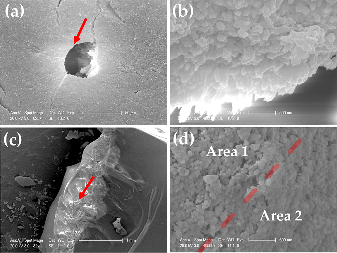
Figure 5 (a), (b) Morphology of entrance holes by impactors and (c), (d) part of track along the impact direction by SEM. The red arrow is marked at the point of observation.
Furthermore, track lengths and size of residual particles were recorded by VMM. As shown in Figure 6(a), the size of projectiles obviously decreased after the impact. Similar to Barrett et al. [Reference Barrett, Zolensky, Horz, Lindstrom and Gibson26], the track length data is also plotted as a function of target density for shots in six different single-density aerogels (#A-1, #B-2, #C-3, listed in Table 1), separately launched at 2.3 and 7 km/s (Figure 6(b)). The dispersed data do not exclude any broken-projectile data, and all are used in this paper. The aerogel track lengths ( $T$) from six impact experiments are normalized to the projectile diameter ( ${D}_{\mathrm{p}}$), which is plotted against target bulk density (Figure 6(c)). In addition, with normalized density of projectile ( ${d}_{\mathrm{p}}$) and aerogel target ( ${d}_{\mathrm{t}}$), the normalized penetration length against density radio ( ${d}_{\mathrm{p}}/{d}_{\mathrm{t}}$) is plotted in Figure 6(d).

Figure 6 Summary of results: (a) plots of the diameter of original and captured projectiles; (b) plots of measured track lengths shown as a function of aerogel target density, all at 2.3 and 7 km/s by impacting (measurement error is  $\pm$0.002 mm); (c) the aerogel track lengths ( $T$) normalized to projectile diameter ( ${D}_{\mathrm{p}}$) against target bulk density; (d) penetration track length scaled ( $T/{D}_{\mathrm{p}}$) against density ratio ( ${d}_{\mathrm{p}}/{d}_{\mathrm{t}}$).
There seems to be no obvious trend that the track lengths are much shorter for denser aerogel with irregular projectiles. Similarly, we attempted to standardize the data, and there is no obvious function of the law. The discrete points of the data that deviates from the overall trend may be caused by uncertain interaction between the aerogels and irregular particles[Reference Barrett, Zolensky, Horz, Lindstrom and Gibson26].
For further study of the irregular phenomenon, parts of the track images are exhibited in Figure 7. Morphologically, this track formation looks just like a projectile intruding into fluid[Reference Niimi, Kadono, Arakawa, Yasui, Dohi, Nakamura, Iida and Tsuchiyama25]. As first described by Tsou et al. [Reference Tsou, Brownlee, Laurance, Hrubesh and Albee3], when grains penetrated into the silica aerogel, gentle curving penetration ‘tracks’ were produced at the same time. The irregular penetration track caused by the uncertain interaction seems to affect the general law of the impact. Meanwhile, the true size and distribution of many fine-scale features such as styli, spiraling ‘petals’, and short lateral ‘spikes’ could be observed in the VMM field of view (e.g., Figure 7(i)), which is also described in detail by Kearsley et al. [Reference Kearsley, Burchell, Price, Cole, Wozniakiewicz, Ishii, Bradley, Fries and Foster4]. This is a manifestation of energy transfer to the capture medium[Reference Domínguez, Westphal, Jones and Phillips29].
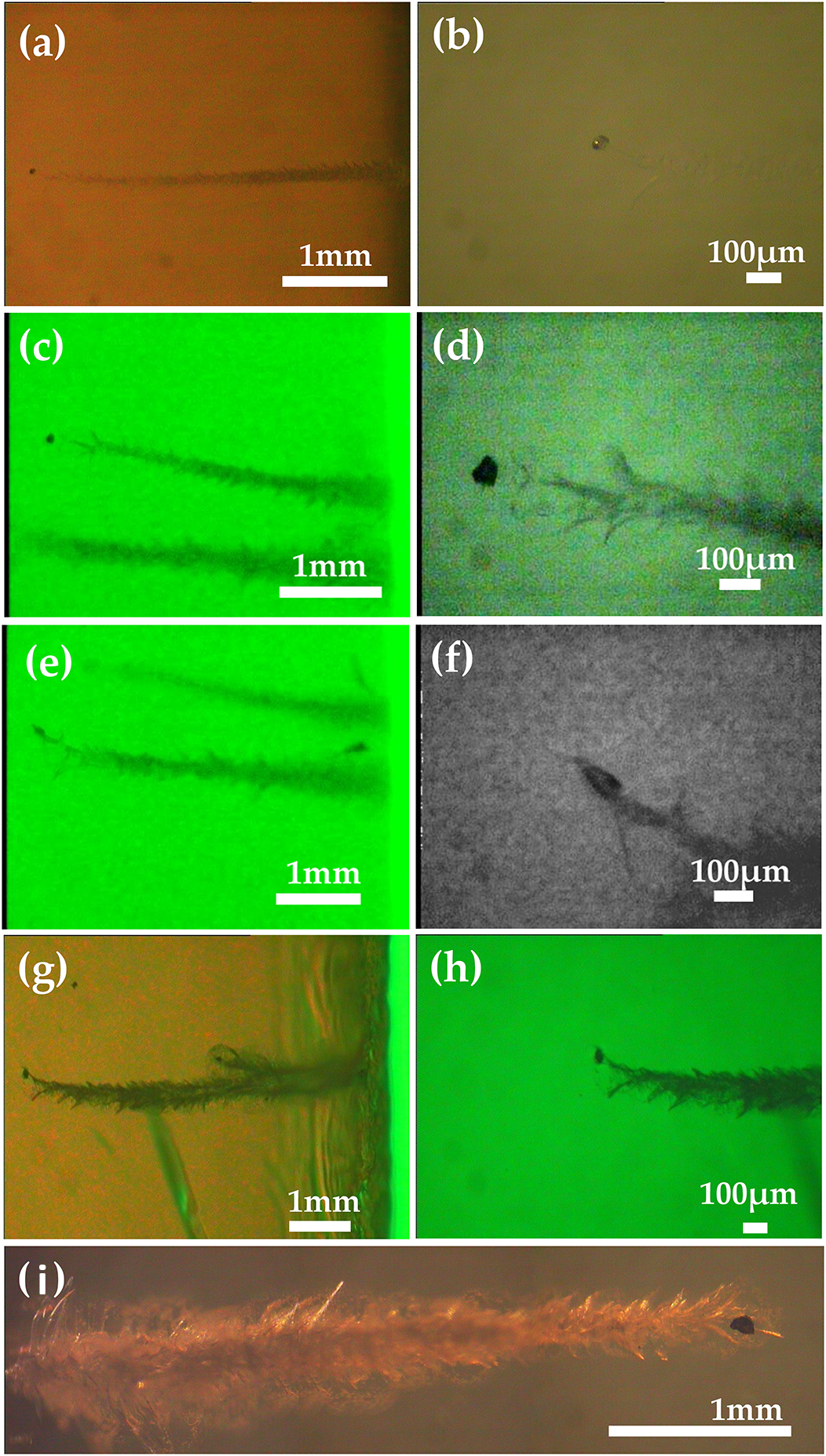
Figure 7 Aerogel tracks created by impacts of Al2O3 obtained by VMM, the impact direction is from the right (except in (e)): (a) the near-spherical captured projectile with the relatively straight track; (b) a near-spherical particle on the terminal track; (c), (d) the irregular captured projectile with the relatively straight track; (e) the detail of track by impact at 2.3 km/s on 182 mg/cm3; (f) flat-shaped projectile residue on the curved track; (g), (h) the residual grain slightly reduced on the curved track; (i) fine features of a track in the aerogel.
Irregularities with irregular shape tracks were further researched. According to the shape of the residues and the possible track path of the projectile (marked by red arrows), the impact tracks by irregular grain status were classified into four types. In addition, the proportions of corresponding states were counted and are displayed in Figure 8.
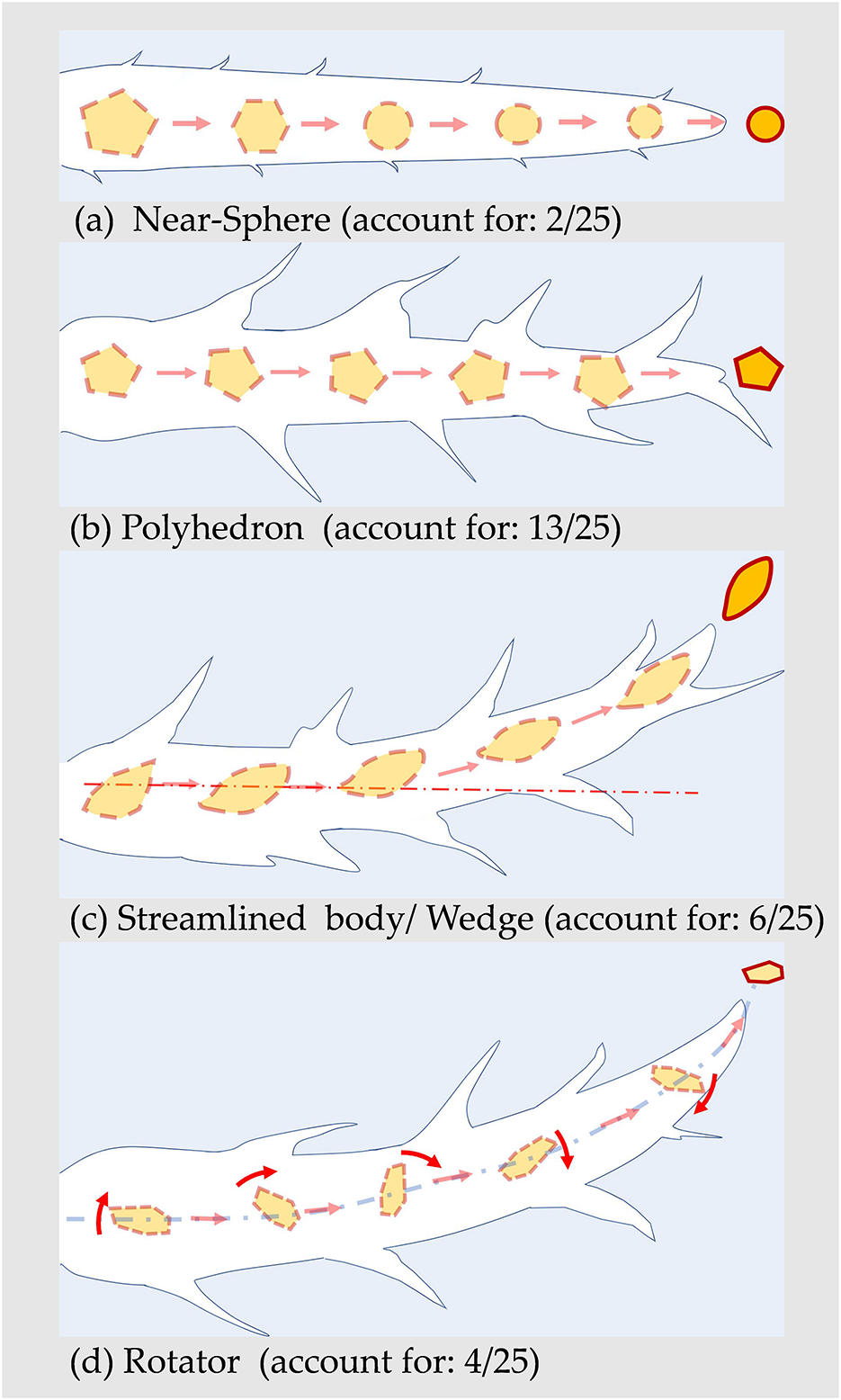
Figure 8 The simplified diagram classified from impact tracks (the impact direction is from the left).
In the observation and classification of tracks, there are some interesting phenomena worth mentioning. For example, when it was judged whether the formation of the track branch was created by grain rupture during the injection process, this may be due to the simultaneous launch of two projectiles (Figure 9(a)). As shown in Figure 9(b), a three-branch track was formed with the rupture from a single particle in the track tail, a simplified diagram of which is given in Figure 9(e). If the projectiles were broken into more fragments (average size  $<15\ \mathrm{\mu} \mathrm{m}$; Figure 9(d)), the situation would be more complicated.

Figure 9 The projectile-breakage situation outside of available data of track classification (the impact direction is from the right): (a) two adjacent grains injected simultaneously into the target, the track branch is not caused by particle breakage; (b) three branches at the track tail caused by a projectile rupture; (c) larger particles and smaller ruptured grains remaining in the track tail; (d) tiny grains spread forward in the local enlargement of (c); (e) simplified diagram of the track shown in (b).
In addition, OCT, nondestructive shooting, was conducted as auxiliary observations for tracks and is displayed in Figure 10. The depth of field was limited along the direction of the track from crater to residues (Figure 10(a)). The dispersion of the micro-crack spreads created by bow shock near the entrance is clear and dramatic, which is inclined to the radial extension outward like tree roots. As shown in Figure 10(b), the spherical defect is the outer surface of the cylindrical sample in the figure. A high-speed particle has passed through these two bubbles from right to left. Compared with Figure 10(b) obtained by VMM, the track scan is divided into two parts (Figures 10(c) and 10(d)) along the track direction. The scanning direction is not strictly parallel to the ‘spikes’ track. The subtle mark left on the track by shock waves that can be observed more clearly by OCT, which is thus proved to be a possibility for checking tracks. Two videos are provided in the supplementary material. They are made from the gather figures scanned along the track and the vertical track, respectively (1 mm range @~71 b-scan/figure).

Figure 10 Aerogel tracks created by impacts of Al2O3 at 7 km/s (the impact direction is from the right). (a) A track-scan photograph along the impact direction. (b) The track photograph just passing through the two spherical bubbles near the cylindrical aerogel side obtained by VMM. (c), (d) The two segments of the track of (b) revealed by OCT.
4 Discussion
Irregular Al2O3 particles were selected as the projectile, shot by the PG at high speed. Residual particles and tracks in aerogel were observed in this paper. Indeed, their nonspherical grain shapes make them difficult to compare with previous and simple calibration projectiles. The differences were compared by comparing the average size of projectiles before and after the impact experiment.
The average size of the projectiles decreased greatly, which could be concluded from the size statistics before and after the impacting experiment (Figure 6(a)). Two kinds of particles were compared, whose maximum lengths were originally 110 $\pm 10$ μm and 251 $\pm 19$ μm. Residues of hypervelocity projectiles captured in aerogels were reduced to 62 $\pm 11$ μm and 73 $\pm 11$ μm, respectively. Owing to holes (defects) on the surface, the Particles-200 projectiles (Figure 1(d)) were more likely to break into fragments in the impact of the experiment. This may result in more loss of size. As shown in Figure 9(d), the projectile was cracked into extremely small fragments during the penetration process, so the measurement (average size <15 μm) was difficult.
There is no denying that owing to the condition of high-temperature and high-pressure plasma, part of the projectile was melted and deformed to some extent. The most obvious evidence is that irregular shapes become spherical (Figure 7(a)). Conducted by PG, the projectiles may undergo some physical alteration (i.e., fragmentation, melting) before impacting the aerogel targets, as described by Kitazawa et al. [Reference Kitazawa, Fujiwara, Kadono, Imagawa, Okada and Uematsu15]. They also pointed out that some projectiles may rupture and ablate when shot by PDA during launch. Furthermore, particles (that can be fragmented), in contact with the aerogel, may undergo thermal decomposition (melting and volatilization) and mixing with volatilized and melted aerogel under the extreme shock temperature[Reference Leroux30]. SEM is used to observe the track to support this heat ablation phenomenon of silica aerogels touched with hypervelocity projectiles (Figures 5(c) and 5(d)). It could be found that areas 1 and 2 appeared in different morphological features. The track wall in porosity has a clear sign of decrease, which is the result of compaction by high-speed projectiles in area 2.
It seems there is no definite relationship between irregular shape and track morphology (Figure 6). In the length of the track, two different sizes of the projectile with two different speeds (Particles-100 @ 7 km/s, Particles-200 @ 2.3 km/s) did not cause significant differences, which is consistent with Barrett et al.'s findings[Reference Barrett, Zolensky, Horz, Lindstrom and Gibson26]. The data is standardized including the track calibration (penetration tracks length-scaled ( $T/{D}_{\mathrm{p}}$), Figure 6(c)), density standardization, and logarithmic processing (penetration tracks length-scaled ( $T/{D}_{\mathrm{p}}$) against density ratio ( ${d}_{\mathrm{p}}/{d}_{\mathrm{t}}$), Figure 6(d)). It seems that there are discrete points of the offset caused by irregular grains with uncertain interaction.
For example, after entering the aerogel target, the instability and tumbling phenomenon of irregular projectiles may be present. The rate that hypervelocity projectiles release kinetic energy to materials is enhanced by the rotation phenomenon. This implies that the residue is most likely to be ultimately stopped because the rotational resistance is too large. The residual projectile eventually is forced to stay at the terminal of the track curvature with the largest cross-section (Figure 7(h)). The projectile penetrating into the aerogel is decelerated, and just before coming to rest, a fracture forms ahead of the projectile[Reference Kitazawa, Fujiwara, Kadono, Imagawa, Okada and Uematsu15]. By contrast, the wedge-shaped (close to streamlined) projectile in Figure 7(f) finally stops moving forward with a minimum area, which suggests that there may not be a rotator.
To study the poor function of irregular tracks caused by irregular projectiles, different tracks and status of particles are classified. The proportion of each category is shown in Figure 8. Irregular particles in the process of penetration may lead to ablation, reduction, and eventually to the near-spherical particle remaining in the track terminal. It rarely left the cracked side of the track and the track wall is relatively smooth (Figures 7(a) and 8(a)). As shown in Figure 8(b), the case of the polyhedron was changed from ablation and reduction of irregular particles after the impact is the highest proportion of all residues (accounts for 13/25 impacts). Some details (e.g., track, grains) are clearly exhibited in Figure 7(e). In addition, the irregular (streamlined, wedge-shaped, etc.) projectile rests on the end of the track with the tip facing forward at the stop status. In addition, the ends of the tracks have a rising trend (Figures 7(e) and 7(f)). As shown in Figure 8(c), it is easier to form a curved track with a streamlined/wedge-shaped projectile (accounting for 6/25 impacts). Owing to the unique shape, the projectile will deviate from the straight line during the penetration process. In addition, there may be a more complicated situation that projectiles in the process of penetration are not only translational, but also rotational, which results in greater track width and more burrs (Figure 7(g)). Owing to the greater loss of energy, the track is shorter and more burred than the near-spherical case.
Irregular grains at high speed penetrate the aerogel targets but deviate from the circular rules at the entrance hole (Figure 4(b)). Before arriving at the impact surface, the high-speed projectile has been melted and deformed to a near-spherical shape during flight with impetus of the plasma. The projectile may enter the track with tumble causing a regular circle shape. However, irregularly shaped entrance holes seem to be much more common. In addition, the entrance size is smaller than the original projectile (Figures 4(c), 4(e), and 4(f)). The impact fracture surface morphology of the entrance hole observed by SEM is shown in Figures 5(a) and 5(b). The hole has an irregular shape, and non-smooth areas of micro-cracks. Aerogel clusters on the track inside of the hole were observed, which was presumably plowed by the edges of irregular projectile.
The tracks seem to be mostly spikes, carrot-shaped, small curves, and deep penetration features, and straighter than with the more regular spherical projectiles. Domínguez et al. [Reference Domínguez, Westphal, Jones and Phillips29] suggested that this meandering behavior may be attributed to the random and asymmetric accretion and shedding of aerogel during capture although they cannot rule out projectile spinning. It seems to be more likely that the short and wide track was left by irregular particles. Compared with the regular particles, irregular particles suffer greater resistance in the penetration process. In addition, this is more likely to occur at the edge of the impact area, which means that the edge of the particle impact cloud has lower velocity.
The projectile would be cracked during the penetration, and the scattered grains end up in different terminal tracks from the initial track (Figures 9(c) and 9(d)). The decomposition of particles eventually was split into the forked tracks although the particle remained intact in the initial part of the track (Figure 9(c)). The morphology is the cone-in-cone structure of the terminal section of tracks and the off-axis location of the impactor residue, which is similar to the track in the Orbital Debris Collector[Reference Hörz, Zolensky, Bernhard, See and Warren6]. This may arise from shock waves.
5 Conclusion
Hypervelocity impact experiments have been carried out using various density aerogel targets and irregular projectiles. The impact experimental data of irregular grains has revealed that there is no clear function between the length of the track, the size of the residual particles, and the impact velocity.
In addition to the basic straight carrot-like track, VMM can be used to observe the process of penetration left by irregular projectiles, where other changes occurred, such as curves and rotations. According to the tracks and status of residues, tracks were classified into four types to explain the possibility of discretization data about penetration length to some extent.
1. Near-spherical residues with relatively smooth tracks.
2. Polyhedron residues changing from ablation and reduction of irregular projectiles.
3. Streamlined/wedge-shaped residues resting on the end of a curved track with the tip facing forward at the stop status.
4. Residues with rotational behavior during the penetration process in the terminal of the track curvature with the largest cross-section.
Compared with the launch of regular projectiles, these uncertain behaviors affect the trend of data points profoundly during penetration. We hope that the morphology analysis of particles and tracks will be helpful in understanding penetration by irregular grains. In addition, the use of OCT was an attempt to obtain the details of the track in a rapid, easy, and nondestructive manner, which will be a potential method for future track observation.
Acknowledgements
This work was supported by the National Key Research and Development Program of China (No. 2017YFA0204600) and the National Natural Science Foundation of China (No. 11874284).


 Open access