


1 Introduction
The technology of high-power fiber laser has made impressive progress in the last decades – output power of single-mode near-diffraction-limited $\text{Yb}$
-doped fiber (YDF) lasers reached
$\text{Yb}$
-doped fiber (YDF) lasers reached ${\sim}$
5 kW when pumped entirely by diodes and
${\sim}$
5 kW when pumped entirely by diodes and ${\sim}$
10 kW with the amplifier in-band tandem pumping[Reference Shi, Fang and Qin1, Reference Zervas and Codemard2]. However, further output power scale-up faces some major obstacles coming from fiber nonlinearities, transverse mode instability (MI) and optical damage, which are very challenging to overcome. Many research groups have been studying alternative techniques to scale up laser power; among them, spectral beam combining (SBC) stands out as a promising one to achieve high brightness laser source[Reference Honea, Afzal, S.-Leuchs, Henrie, Brar, Kurz, Jander, Gitkind, Hu, Robin, Jones, Kasinadhuni and Humphreys3–Reference Ma, Jiang, Wang, Ma, Zhou and Liu7].
${\sim}$
10 kW with the amplifier in-band tandem pumping[Reference Shi, Fang and Qin1, Reference Zervas and Codemard2]. However, further output power scale-up faces some major obstacles coming from fiber nonlinearities, transverse mode instability (MI) and optical damage, which are very challenging to overcome. Many research groups have been studying alternative techniques to scale up laser power; among them, spectral beam combining (SBC) stands out as a promising one to achieve high brightness laser source[Reference Honea, Afzal, S.-Leuchs, Henrie, Brar, Kurz, Jander, Gitkind, Hu, Robin, Jones, Kasinadhuni and Humphreys3–Reference Ma, Jiang, Wang, Ma, Zhou and Liu7].
Due to the spectral dispersion of the dispersive elements used in the SBC such as multilayer dielectric gratings[Reference Honea, Afzal, S.-Leuchs, Henrie, Brar, Kurz, Jander, Gitkind, Hu, Robin, Jones, Kasinadhuni and Humphreys3, Reference Wirth, Schmidt, Tsybin, Schreiber, Eberhardt, Limpert, Tünnermann, Ludewigt, Gowin, ten Have and Jung4] or volume Bragg gratings[Reference Ott, Divliansky, Anderson, Venus and Glebov5], the linewidth of each individual beam has to be reasonably narrow in order to endure the quality of the combined beam. Therefore, a narrow-linewidth YDF laser has attracted considerable attention for further brightness scaling. In Ref. [Reference Honea, Afzal, S.-Leuchs, Henrie, Brar, Kurz, Jander, Gitkind, Hu, Robin, Jones, Kasinadhuni and Humphreys3], 96 channels of ${\sim}$
300 W fiber lasers were combined into one single beam of 30-kW output power, which is the typical milestone in high-power SBC. Power scaling should be expected if the output power of each element could be increased to kW level. In fact, Zheng et al. reported an eight-element fiber laser SBC system that achieved 10.8 kW, and each channel were 1.5 kW[Reference Zheng, Yang, Wang, Hu, Liu, Zhao, Chen, Liu, Zhao, He and Zhou6]. However, three-stage YDF amplifier chains were used in order to boost the output power of the narrowband laser seed, that made the individual laser element complicated. To obtain high-power narrow-linewidth laser source, many works were based on cascaded multi-stage power amplification scheme to boost the output power[Reference Naderi, Dajani and Flores8–Reference Huang, Wu, Li, Li, Ma, Wang, Leng and Zhou11]. Moreover, in an SBC system, a polarization-independent multilayer dielectric diffraction grating had been used and each individual laser element was randomly polarized with a diffraction efficiency of 94%[Reference Zheng, Yang, Wang, Hu, Liu, Zhao, Chen, Liu, Zhao, He and Zhou6], while the diffraction efficiency of the polarization-dependent multilayer dielectric grating can be as high as 97%[Reference Clausnitzer, Limpert, Zöllner, Zellmer, Fuchs, Kley, Tünnermann, Jupé and Ristau12]. Thus, one can increase the combined efficiency by employing the linearly polarized laser array. Therefore, high-power linearly polarized fiber laser channel with compact structure would optimize the performance of SBC system.
${\sim}$
300 W fiber lasers were combined into one single beam of 30-kW output power, which is the typical milestone in high-power SBC. Power scaling should be expected if the output power of each element could be increased to kW level. In fact, Zheng et al. reported an eight-element fiber laser SBC system that achieved 10.8 kW, and each channel were 1.5 kW[Reference Zheng, Yang, Wang, Hu, Liu, Zhao, Chen, Liu, Zhao, He and Zhou6]. However, three-stage YDF amplifier chains were used in order to boost the output power of the narrowband laser seed, that made the individual laser element complicated. To obtain high-power narrow-linewidth laser source, many works were based on cascaded multi-stage power amplification scheme to boost the output power[Reference Naderi, Dajani and Flores8–Reference Huang, Wu, Li, Li, Ma, Wang, Leng and Zhou11]. Moreover, in an SBC system, a polarization-independent multilayer dielectric diffraction grating had been used and each individual laser element was randomly polarized with a diffraction efficiency of 94%[Reference Zheng, Yang, Wang, Hu, Liu, Zhao, Chen, Liu, Zhao, He and Zhou6], while the diffraction efficiency of the polarization-dependent multilayer dielectric grating can be as high as 97%[Reference Clausnitzer, Limpert, Zöllner, Zellmer, Fuchs, Kley, Tünnermann, Jupé and Ristau12]. Thus, one can increase the combined efficiency by employing the linearly polarized laser array. Therefore, high-power linearly polarized fiber laser channel with compact structure would optimize the performance of SBC system.
In order to develop more simple and compact designs to achieve both narrow linewidth and high power, many research groups have demonstrated the methods based on master oscillator power amplifier (MOPA) structure to scale up the output power of narrow-linewidth laser oscillator directly.
Hao et al. reported an all-fiber narrow-linewidth amplifier seeded by a laser oscillator by use of a pair of extremely narrow-bandwidth fiber Bragg gratings (FBGs). The 13-dB reflection bandwidth was 0.1 and 0.05 nm for the high reflective (HR) FGB and the output coupler (OC) FGB, respectively[Reference Hao, Zhao and Zhang13]. Although a narrow linewidth of 0.08 nm at an output power of 823 W had been obtained, a cavity requiring such precision wavelength matching is difficult to maintain since a temperature change of $0.1^{\circ }\text{C}$
will result in a wavelength change of 1 pm for an FBG[Reference Kersey, Davis, Patrick, Leblanc, Koo, Askins, Putnam and Friebele14]. Thus, a few degree temperature offset between the two FBGs would deteriorate the cavity’s Q-factor substantially.
$0.1^{\circ }\text{C}$
will result in a wavelength change of 1 pm for an FBG[Reference Kersey, Davis, Patrick, Leblanc, Koo, Askins, Putnam and Friebele14]. Thus, a few degree temperature offset between the two FBGs would deteriorate the cavity’s Q-factor substantially.
The method to achieve narrow-linewidth output was also demonstrated by shortening the gain fiber lengths for both oscillator and amplifier. Very recently, Huang et al. demonstrated a 2.9 kW YDF amplifier with an output linewidth of 60 pm for the seed laser and 310 pm for the amplifier[Reference Huang, Liang, Li, Lin, Li, Wang and Jing15]. Another attempt to achieve both narrow linewidth and high power was reported by using a master oscillator of ${\sim}$
25 GHz (96 pm) at 6 W output power and obtained
${\sim}$
25 GHz (96 pm) at 6 W output power and obtained ${\sim}$
75 GHz (286 pm) linewidth at 2 kW output[Reference Xu, Fang, Qin, Meng and Shi16]. Due to the insufficient power of the seed laser, two-stage amplifiers were used to suppress the amplified spontaneous emission (ASE) effectively. This design, despite the success, was complicated the same as the aforementioned cascaded multi-stage power amplification scheme. If a high-power narrow-linewidth laser source based on single-stage power-scaling scheme can be demonstrated, it would relatively simplify the laser system and reduce the costing[Reference Xu, Xiao, Leng, Zhang, Zhou and Chen17, Reference Yang, Xu, Mo, Li, Feng, Chen, Yang and Jiang18]. Besides, the outputs of those three reports mentioned before were not linearly polarized.
${\sim}$
75 GHz (286 pm) linewidth at 2 kW output[Reference Xu, Fang, Qin, Meng and Shi16]. Due to the insufficient power of the seed laser, two-stage amplifiers were used to suppress the amplified spontaneous emission (ASE) effectively. This design, despite the success, was complicated the same as the aforementioned cascaded multi-stage power amplification scheme. If a high-power narrow-linewidth laser source based on single-stage power-scaling scheme can be demonstrated, it would relatively simplify the laser system and reduce the costing[Reference Xu, Xiao, Leng, Zhang, Zhou and Chen17, Reference Yang, Xu, Mo, Li, Feng, Chen, Yang and Jiang18]. Besides, the outputs of those three reports mentioned before were not linearly polarized.
In this paper, we use a single-stage amplifier to scale linearly polarized fiber laser to kW level while maintaining a narrow spectral linewidth. Our results show that this MOPA scheme achieved a linearly polarized laser output with average power of 1018 W and a narrow linewidth of 0.3 nm. Moreover, due to the good beam quality of seed laser and the well-designed amplifier stage, the output laser has a near-diffraction-limited beam quality with $M_{x}^{2}\sim 1.18$
and
$M_{x}^{2}\sim 1.18$
and $M_{y}^{2}\sim 1.24$
at the maximum power without MI occurring.
$M_{y}^{2}\sim 1.24$
at the maximum power without MI occurring.
2 Experiments
Figure 1 shows a schematic diagram of the 1 kW narrow spectral width all-fiber amplifier structure. The MOPA configuration consisted of a CW fiber laser oscillator and a double cladding fiber amplifier.
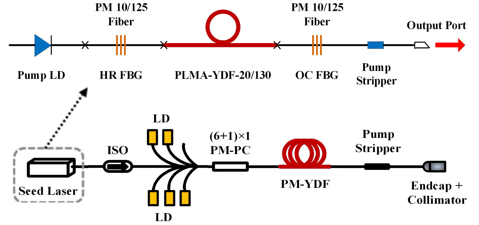
Figure 1. Experimental setup of the narrow-linewidth, linearly polarized seed laser and fiber amplifier. LD: laser diode; PC: polarization controller; ISO: isolator.
The oscillator is a linear cavity laser, consisting of a pair of FBGs and a piece of gain YDF. The FBG with an HR-FBG of 99% at 1064 nm is spliced to one end of the gain fiber with the axes of both fiber aligned. The OC-FBG with a reflectivity of 10% is spliced to the other end of the gain fiber after a $90^{\circ }$
rotation. The spectra of the HR-FBG and OC-FBG, as shown in Figure 2, are shifted for the purpose of polarization selection: fast axis wavelength of the HR-FBG (1064.226 nm) matches with the slow axis wavelength of the OC-FBG (1064.251 nm) within a tolerance of 30 pm. The full width at half maximum (FWHM) bandwidth of the HR-FBG is 0.235 nm and 0.17 nm for OC-FBG, respectively.
$90^{\circ }$
rotation. The spectra of the HR-FBG and OC-FBG, as shown in Figure 2, are shifted for the purpose of polarization selection: fast axis wavelength of the HR-FBG (1064.226 nm) matches with the slow axis wavelength of the OC-FBG (1064.251 nm) within a tolerance of 30 pm. The full width at half maximum (FWHM) bandwidth of the HR-FBG is 0.235 nm and 0.17 nm for OC-FBG, respectively.

Figure 2. Reflection spectra of the HR-FBG and transmission spectra of OC-FBG on fast and slow axis, respectively.
Another design is employed in the cavity in order to reduce the intensity in the core of gain fiber and thus reduce self-phase modulation (SPM) effect. A 1.3 m long $20/130~\unicode[STIX]{x03BC}\text{m}$
multimode YDF (PLMA-YDF-20/130, Nufern Inc.) with a nominal cladding absorption coefficient of 10.2 dB/m at 976 nm is used as the gain fiber and two pieces of
$20/130~\unicode[STIX]{x03BC}\text{m}$
multimode YDF (PLMA-YDF-20/130, Nufern Inc.) with a nominal cladding absorption coefficient of 10.2 dB/m at 976 nm is used as the gain fiber and two pieces of $10/125~\unicode[STIX]{x03BC}\text{m}$
fiber (PLMA-GDF-10/125, Nufern Inc.) are used to inscribe FBGs; thus the cavity consists of an single-mode–multimode–single-mode (SMS) design. The SMS design was used in Refs. [Reference Jiang, Xu, Zhou, Zhao and Gu19–Reference Jiang, Zhou, Xiao and Ma22] before which suppressed Raman emission and reduced SPM-induced linewidth broadening. However, in this design we attempted to use polarization-maintaining (PM) fibers to construct an SMS cavity. Moreover, we use larger mode area gain fiber by comparison with Ref. [Reference Jiang, Xu, Zhou, Zhao and Gu19] to see if it would increase power conversion efficiency, meanwhile reducing SPM effect which would broaden the laser linewidth.
$10/125~\unicode[STIX]{x03BC}\text{m}$
fiber (PLMA-GDF-10/125, Nufern Inc.) are used to inscribe FBGs; thus the cavity consists of an single-mode–multimode–single-mode (SMS) design. The SMS design was used in Refs. [Reference Jiang, Xu, Zhou, Zhao and Gu19–Reference Jiang, Zhou, Xiao and Ma22] before which suppressed Raman emission and reduced SPM-induced linewidth broadening. However, in this design we attempted to use polarization-maintaining (PM) fibers to construct an SMS cavity. Moreover, we use larger mode area gain fiber by comparison with Ref. [Reference Jiang, Xu, Zhou, Zhao and Gu19] to see if it would increase power conversion efficiency, meanwhile reducing SPM effect which would broaden the laser linewidth.
A 90-W 976 nm fiber-coupled multimode laser diode (MMLD) is utilized to end-pump the active fiber. The residual pump light and some signal laser propagating in the fiber cladding are leaked out by using a power stripper at the output end of the oscillator. At the rear end ports of the oscillator, a PM isolator is incorporated into the MOPA structure to block off the backward powers from the following amplification, the backward ASE for example, to protect the oscillator. The seed oscillator can produce output power of ${\sim}$
45 W with slope efficiency of
${\sim}$
45 W with slope efficiency of ${\sim}$
64.8%, as shown in Figure 3(a), and further power scaling would be achieved by increasing pump power and adding hydrocooling. The
${\sim}$
64.8%, as shown in Figure 3(a), and further power scaling would be achieved by increasing pump power and adding hydrocooling. The $-3$
dB bandwidth of output emission spectra measured at different output power were
$-3$
dB bandwidth of output emission spectra measured at different output power were ${\leqslant}$
44 pm as shown in Figure 3(b). One can see that the slope efficiency of this laser is less than that in Ref. [Reference Jiang, Xu, Zhou, Zhao and Gu19] (with slope efficiency of
${\leqslant}$
44 pm as shown in Figure 3(b). One can see that the slope efficiency of this laser is less than that in Ref. [Reference Jiang, Xu, Zhou, Zhao and Gu19] (with slope efficiency of ${\sim}$
68.5%), due to the splicing loss between
${\sim}$
68.5%), due to the splicing loss between $20/130~\unicode[STIX]{x03BC}\text{m}$
YDF and
$20/130~\unicode[STIX]{x03BC}\text{m}$
YDF and $10/125~\unicode[STIX]{x03BC}\text{m}$
fiber is larger than that between
$10/125~\unicode[STIX]{x03BC}\text{m}$
fiber is larger than that between $15/130~\unicode[STIX]{x03BC}\text{m}$
YDF and
$15/130~\unicode[STIX]{x03BC}\text{m}$
YDF and $10/125~\unicode[STIX]{x03BC}\text{m}$
fiber. However, the output spectral widths in this paper become narrower compared to Ref. [Reference Jiang, Xu, Zhou, Zhao and Gu19], in which the
$10/125~\unicode[STIX]{x03BC}\text{m}$
fiber. However, the output spectral widths in this paper become narrower compared to Ref. [Reference Jiang, Xu, Zhou, Zhao and Gu19], in which the $-3$
dB bandwidth started at 42 pm and increased up to 52 pm at 32.7 W. Due to the large mode area (LMA) gain fiber which would reduce the SMP effect in laser cavity, the seed laser in this paper obtains a higher output power, meanwhile maintaining the linewidth narrower. Moreover, the polarization extinction ratio (PER) at maximum output power is measured to be
$-3$
dB bandwidth started at 42 pm and increased up to 52 pm at 32.7 W. Due to the large mode area (LMA) gain fiber which would reduce the SMP effect in laser cavity, the seed laser in this paper obtains a higher output power, meanwhile maintaining the linewidth narrower. Moreover, the polarization extinction ratio (PER) at maximum output power is measured to be ${>}15$
dB. Due to such performance of this laser, when used as a master oscillator, it should be capable of scaling up the output power to multi-kW level by a single-stage amplifier while maintaining a narrow spectral linewidth.
${>}15$
dB. Due to such performance of this laser, when used as a master oscillator, it should be capable of scaling up the output power to multi-kW level by a single-stage amplifier while maintaining a narrow spectral linewidth.

Figure 3. Master oscillator: (a) laser output power versus pump power; (b) spectral linewidth at different output power.
The power amplifier is pumped by five wavelength-stabilized, 300 W power-level laser diodes (LDs) with 976 nm central wavelength via a ( $6+1$
)
$6+1$
) $\times 1$
PM pump combiner. The active fiber in this stage is LMA and double clad PM YDF with a core diameter of
$\times 1$
PM pump combiner. The active fiber in this stage is LMA and double clad PM YDF with a core diameter of $20~\unicode[STIX]{x03BC}\text{m}$
and an inner cladding diameter of
$20~\unicode[STIX]{x03BC}\text{m}$
and an inner cladding diameter of $400~\unicode[STIX]{x03BC}\text{m}$
(PLMA-YDF-20/400). The cladding absorption coefficient is about 1.7 dB/m at 976 nm and an 8.5 m long active fiber is employed for high-power scaling. It is to be noted that in this amplifier, in order to suppress MI effect effectively and maintain good beam quality, the active fiber is coiling with radius of
$400~\unicode[STIX]{x03BC}\text{m}$
(PLMA-YDF-20/400). The cladding absorption coefficient is about 1.7 dB/m at 976 nm and an 8.5 m long active fiber is employed for high-power scaling. It is to be noted that in this amplifier, in order to suppress MI effect effectively and maintain good beam quality, the active fiber is coiling with radius of ${\sim}$
5.5 cm[Reference Ma, Tao, Su, Wang, Zhou and Liu10, Reference Tao, Ma, Wang, Zhou and Liu23]. About 1 m long PM passive fiber and a high-power fiber end-cap with
${\sim}$
5.5 cm[Reference Ma, Tao, Su, Wang, Zhou and Liu10, Reference Tao, Ma, Wang, Zhou and Liu23]. About 1 m long PM passive fiber and a high-power fiber end-cap with ${\sim}$
1.5 m long PM passive fiber are successively fused to the rear end of the active fiber for power delivering. The core and inner cladding diameters of the two pieces of passive fibers remain the same as the active fiber. In the 1 m long passive fiber, an
${\sim}$
1.5 m long PM passive fiber are successively fused to the rear end of the active fiber for power delivering. The core and inner cladding diameters of the two pieces of passive fibers remain the same as the active fiber. In the 1 m long passive fiber, an ${\sim}$
40 cm high-index gel section is made for stripping out the residual pump and cladding light. The delivering laser through the fiber end-cap is collimated into free space by using a high-power beam collimator.
${\sim}$
40 cm high-index gel section is made for stripping out the residual pump and cladding light. The delivering laser through the fiber end-cap is collimated into free space by using a high-power beam collimator.
3 Results and Discussions
Output power of this amplifier as a function of pump power is measured within 20 W seed laser injection. At 1336 W coupled pump power, up to 1018 W laser output is obtained with an overall slope efficiency ${\sim}$
78.6%, as shown in Figure 4.
${\sim}$
78.6%, as shown in Figure 4.

Figure 4. Laser output power versus pump power.
An optical spectrum analyzer (ANDO Corp. model AQ6317) with 0.01 nm resolution is used to measure the spectral characteristics of the output laser. The spectrum at the maximum output power is plotted in Figure 5, which shows that the center wavelength is located at 1064.36 nm and an optical signal to noise ratio of ${\sim}$
40 dB is achieved. No residual power at 976 nm and ASE spectra is observed.
${\sim}$
40 dB is achieved. No residual power at 976 nm and ASE spectra is observed.

Figure 5. Optical spectrum at 1018 W maximum laser.
A close-up view of the output laser spectra is shown in Figure 6, in which, the optical signal-noise ratio (OSNR) is about 35 dB across all output power levels. After the one-stage fiber amplifiers, the $-3$
dB bandwidth and
$-3$
dB bandwidth and $-10$
dB bandwidth of the laser emission spectra are measured, respectively, at different output powers as shown in Figure 7. Due to the nonlinear effects including SPM and four-wave mixing (FWM), the
$-10$
dB bandwidth of the laser emission spectra are measured, respectively, at different output powers as shown in Figure 7. Due to the nonlinear effects including SPM and four-wave mixing (FWM), the $-3$
dB bandwidth starts at 0.1 nm and increases up to 0.3 nm at 1018 W, meanwhile the corresponding
$-3$
dB bandwidth starts at 0.1 nm and increases up to 0.3 nm at 1018 W, meanwhile the corresponding $-10$
dB bandwidth increases from 0.2 nm to 0.9 nm. By increasing injection seed power or adding pump power would enhance the output power of the amplifier.
$-10$
dB bandwidth increases from 0.2 nm to 0.9 nm. By increasing injection seed power or adding pump power would enhance the output power of the amplifier.

Figure 6. An enlarged view of the laser spectrum at different output power.

Figure 7. Spectral linewidth as a function of laser power.
The PER is measured with a high-quality polarization beam splitter (PBS). The laser power transmitted through, and reflected by the PBS is measured consecutively when the power from one polarization is minimized by rotating the collimated laser beam. The PER is obtained from the ratio of the two power readings at different output power. The measured PER is reached 14 dB at maximum output power.
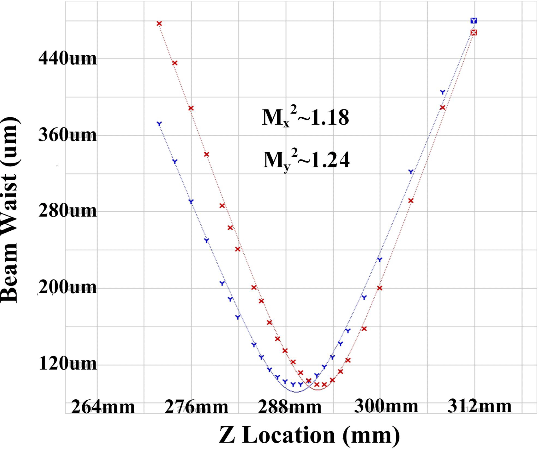
In addition, the well-designed PM amplifier which is operated stably contributes to the excellent beam quality of the kW-level amplifier output beam. As Figure 8 shows, using a beam profile analyzer ( $M^{2}$
–200) the beam quality factor
$M^{2}$
–200) the beam quality factor $M^{2}$
is measured to be
$M^{2}$
is measured to be ${\sim}$
1.18 and
${\sim}$
1.18 and ${\sim}$
1.24 in the
${\sim}$
1.24 in the $x$
and
$x$
and $y$
directions respectively, for the laser beam with 1018 W output power. Nearly diffraction-limited beam quality is achieved.
$y$
directions respectively, for the laser beam with 1018 W output power. Nearly diffraction-limited beam quality is achieved.

Figure 8. Beam quality factor ( $M^{2}$
) of the output laser beam at 1018 W.
$M^{2}$
) of the output laser beam at 1018 W.
4 Conclusions
In summary, we have successfully demonstrated a kW-level linearly polarized laser source with narrow linewidth and near-diffraction-limited beam quality based on a compact power-scaling configuration. By employing a high-power SMS structure seed laser, only one-stage amplification is used to scale up the output power to 1018 W with a slope efficiency of ${\sim}78.6\%$
. It has the linearly polarized output with a PER of 14 dB, and a narrow linewidth of below 0.3 nm is obtained. Due to the good beam quality of seed laser and the well-designed amplifier stage, the beam quality of the output laser is near-diffraction-limited with
${\sim}78.6\%$
. It has the linearly polarized output with a PER of 14 dB, and a narrow linewidth of below 0.3 nm is obtained. Due to the good beam quality of seed laser and the well-designed amplifier stage, the beam quality of the output laser is near-diffraction-limited with $M_{x}^{2}\sim 1.18$
and
$M_{x}^{2}\sim 1.18$
and $M_{y}^{2}\sim 1.24$
without MI occurring at the maximum power. The output power of the laser amplifier could still be enhanced by increasing injection seed power or adding pump power. It is worth mentioning that the principle of our design is general and can be applied to other wavelengths of the fiber amplifier. This all-fiber single-stage amplification construction of the whole MOPA system enables compact size and robust operation. In addition, the narrow-linewidth linearly polarized high-power amplifiers are also desirable for many important applications such as beam combining, lidar, laser materials processing, etc.
$M_{y}^{2}\sim 1.24$
without MI occurring at the maximum power. The output power of the laser amplifier could still be enhanced by increasing injection seed power or adding pump power. It is worth mentioning that the principle of our design is general and can be applied to other wavelengths of the fiber amplifier. This all-fiber single-stage amplification construction of the whole MOPA system enables compact size and robust operation. In addition, the narrow-linewidth linearly polarized high-power amplifiers are also desirable for many important applications such as beam combining, lidar, laser materials processing, etc.
Acknowledgements
This work was supported by Huo Ying Dong Education Foundation of China (No. 151062) and the Foundation for the author of National Excellent Doctoral Dissertation of China (No. 201329).


 Open access