


Impact Statement
In offshore offloading operations, two vessels are usually in a side-by-side configuration, and tanks on the vessel may experience partially filled conditions. To ensure operational safety and avoid potential hazard of collision, the understanding of wave induced motions of vessels with liquid sloshing effects is paramount. In this study, we consider water wave interactions with side-by-side barges in a fixed–free deployment accounting for liquid sloshing in internal tanks. To investigate complex interactions among water waves, multibody system and liquid sloshing in internal tanks, a numerical model based on the boundary element method is developed, and the validity is tested by physical experiments. This study not only provides reference for numerical simulations, but also gives an insight into the motion characteristics of a floating vessel with/without liquid sloshing effects alongside a stationary vessel.
1. Introduction
The push to develop offshore natural gas resources, as a transition fuel with lower carbon emissions, has necessitated the development of open-sea side-by-side offloading operations, where a liquefied natural gas carrier is moored alongside a floating liquefied natural gas platform using a combination of hawsers and fenders that concurrently holds the vessels in the desired position while preventing contact between the two vessels. With the transformation towards alternative fuels such as liquid ammonia and hydrogen, the understanding of side-by-side transfer operations will become more pertinent due to the potential hazards such as toxicity and explosiveness.
Because of its practical and theoretical importance, the hydrodynamics concerning side-by-side vessels has been extensively studied, and focus has been placed on the physics of fluid resonance occurring in a narrow gap between two vessels which may directly influence operational safety (Reference Chua, Eatock Taylor and ChooChua, Eatock Taylor, & Choo, 2018; Reference Faltinsen, Rognebakke and TimokhaFaltinsen, Rognebakke, & Timokha, 2007; Reference Kristiansen and FaltinsenKristiansen & Faltinsen, 2012; Reference MolinMolin, 2001; Reference Sun, Eatock Taylor and TaylorSun, Eatock Taylor, & Taylor, 2010; Reference Zhao, Taylor, Wolgamot and Eatock TaylorZhao, Taylor, Wolgamot, & Eatock Taylor, 2021; Reference Zhao, Wolgamot, Taylor and Eatock TaylorZhao, Wolgamot, Taylor, & Eatock Taylor, 2017, and the references therein). Due to the narrow nature of the gap between two vessels, fluid resonance may occur, and thus viscous effects are non-negligible resulting in an overprediction of the potential-flow model (Reference Faltinsen, Rognebakke and TimokhaFaltinsen et al., 2007; Reference Kristiansen and FaltinsenKristiansen & Faltinsen, 2008). Reference Feng and BaiFeng and Bai (2015) argued that the free-surface nonlinearities have limited effects on the amplitude of waves in the gap, but result in a shift in resonant frequency. Therefore the overprediction is due to viscous effects which is confirmed in Reference Kristiansen and FaltinsenKristiansen and Faltinsen (2008), Reference Faltinsen and TimokhaFaltinsen and Timokha (2015) and Reference Tan, Lu, Tang, Cheng and ChenTan, Lu, Tang, Cheng, and Chen (2019). To minimise the overprediction by potential-flow models, a damping term can be included in the free-surface condition in the gap (Reference ChenChen, 2004; Reference Faltinsen and TimokhaFaltinsen & Timokha, 2015; Reference Liang, Chua, Wang and ChooLiang, Chua, Wang, & Choo, 2021; Reference Tan, Lu, Tang, Cheng and ChenTan et al., 2019). For round bilge corners, the damping mainly stems from the wall friction due to laminar boundary layers, and thus exhibits linear behaviours (Reference Wang, Wolgamot, Draper, Zhao, Taylor and ChengWang et al., 2019; Reference Zhao, Taylor, Wolgamot and Eatock TaylorZhao, Taylor, Wolgamot, & Eatock Taylor, 2018). For square corners, however, both linear and quadratic damping terms associated with the wall friction and flow separation from bilges matter (Reference Liang, Chua, Wang and ChooLiang et al., 2021; Reference Tan, Lu, Tang, Cheng and ChenTan et al., 2019).
When the bodies are freely floating, the resonant peak is appreciably reduced and the resonant frequency is shifted, given that part of the incident wave energy would be expended to drive the motions of the two floating bodies (Reference Fredriksen, Kristiansen and FaltinsenFredriksen, Kristiansen, & Faltinsen, 2015). Compared with fixed vessels, floating vessels in a side-by-side arrangement are of more practical importance. Reference Feng and BaiFeng and Bai (2017) investigated the influence of connection constraints on motions of side-by-side barges using a fully nonlinear potential-flow model. Reference Lu, Tan, Zhou, Zhao and IkomaLu, Tan, Zhou, Zhao, and Ikoma (2020) looked into the effect of mooring stiffness on gap resonance and wave induced motion of a barge moored to a vertical wall. Reference Huang, Li, Chen and AraujoHuang, Li, Chen, and Araujo (2018) and Reference Li, Liang, Chen and AraujoLi, Liang, Chen, and Araujo (2021) studied a more complicated non-parallel side-by-side configuration which is closely linked to gangway motions in engineering practice. Despite the hydrodynamics of side-by-side vessels having been widely studied, the side-by-side vessels coupled with liquid sloshing in internal tanks has seldom been considered in the literature, and therefore little is known about the underlying physics.
In a side-by-side offloading operation, both the floating platform and offtake vessel are expected to experience partially filled conditions, where a free surface exists within the liquid cargo tanks. Therefore, the liquid sloshing in tanks occurs due to vessel motions. From a hydrostatic point of view, the inclination of the free surface in tanks leads to the change in the metacentric height affecting the hydrostatic restoring forces on the vessel (Reference MolinMolin, 2002a).
Concerning the hydrodynamic aspects, the liquid sloshing produces dynamic effects, creating an extra added mass and moment of inertia (Reference Faltinsen and TimokhaFaltinsen & Timokha, 2009). As a consequence, the wave induced motions as well as natural periods are changed because of liquid sloshing in internal tanks. The analytical aspects and fundamental knowledge of liquid sloshing in a tank are summarised in Reference Faltinsen and TimokhaFaltinsen and Timokha (2009). For a tank with a simple geometry (rectangular or cylindrical), the natural modes and natural frequencies can be analytically determined. Moreover, Reference Faltinsen and TimokhaFaltinsen and Timokha (2014) also obtained the approximated natural modes and natural frequencies of a prismatic tank, which is of practical significance in marine operations. The determination of the lowest natural frequency can help us to understand when severe liquid sloshing occurs.
Based on the assumption of linear sloshing flows inside the tank, Reference MolinMolin (2002b), Reference Malenica, Zalar and ChenMalenica, Zalar, and Chen (2003) and Reference NewmanNewman (2005) studied the coupled ship motion and liquid sloshing in the frequency domain, providing a theoretical foundation for subsequent studies. Within the framework of linear potential-flow theory, the liquid sloshing only contributes to the added mass (and moment of inertia) term. Furthermore, the added mass due to liquid sloshing can be infinite when the incident wave frequency coincides with the natural frequency of sloshing, leading to zero motions, and corresponding frequencies are referred to as ‘Stokes’ natural frequencies. Reference Faltinsen and TimokhaFaltinsen and Timokha (2021) reported that the natural frequencies with coupling effects differ from ones without coupling, and ones accounting for vessel coupling effects are referred to as ‘non-Stokes’ natural frequencies. The non-Stokes natural frequencies are dependent on vessel geometries. At non-Stokes natural frequencies, large vessel motions are excited.
In the present study, the hydrodynamics of side-by-side barges with round corners coupled with liquid sloshing effects is studied for a fixed–free arrangement. To obtain realistic motion responses near resonance, a damping surface is devised on the free surface in between two barges. The rest of the paper is organised as follows. Section 2 sets forth the numerical modelling of water wave interactions with a multibody system coupled with liquid sloshing effects based on the linear potential-flow theory. Section 3 describes the experimental campaign and particulars of the facilities. The numerical results and experimental validations are shown in § 4, and in-depth discussions about vessel motions are provided. In § 5, concluding remarks are presented.
2. Numerical modelling of multibody hydrodynamics
The numerical modelling of interactions between water waves and two side-by-side barges in a fixed–free arrangement with liquid sloshing effects is now considered. Without loss of generality, we suppose there are  $N$ bodies floating in deep water. A Cartesian coordinate system $Oxyz$ is defined with the $Oxy$ plane coinciding with the undisturbed free surface, and the $Oz$ axis pointing positive upward. For the interaction between water waves and large-volume marine structures, the inertial effect is predominant, whereas the viscous effect plays a secondary role (Reference FaltinsenFaltinsen, 1993; Reference MolinMolin, 2002a). Therefore, we assume that the fluid is incompressible and inviscid, and flow is irrotational so that a velocity potential $\varPhi$ satisfying $\nabla ^2\varPhi =0$ exists. The velocity potential in the flow field is expressed as
 \begin{equation} \varPhi({\boldsymbol x},t) = \mathrm{Re}\left\{\left[\phi_0({\boldsymbol x}) + \sum_{n = 1}^{N}\phi_{7}^{n}({\boldsymbol x}) -\mathrm{i}\omega\sum_{n = 1}^{N}\sum_{j = 1}^{6}X_j^{n}\phi_j^{n}({\boldsymbol x}) \right]\,\mathrm{e}^{-\mathrm{i}\omega t}\right\}, \end{equation}
where  $\omega$ is the angular frequency of oscillation, and $t$ is time. In (2.1), $\phi _{j}^{n}$, with $j=1,2,\ldots,6$, denote radiation potentials due to the motion of the $n$th body, $\phi _{7}^{n}$ the scattering potential due to the $n$th body and $\phi _{0}$ the incident wave potential expressed as (Reference NewmanNewman, 1977)
 \begin{equation} \phi_{0} = {-}\mathrm{i}\frac{ag}{\omega}\,\mathrm{e}^{k_0z + \mathrm{i} k_0(x\cos\beta + y\sin\beta)}, \end{equation}
where  $a$ denotes the wave amplitude, $g$ the acceleration due to gravity, $\beta$ the wave incidence angle and $k_0=\omega ^2/g$ the wavenumber in deep water.
2.1 Radiation and diffraction analysis of ship motions
To determine the radiation potential and scattering potential, the boundary element method is adopted. Due to the presence of a narrow gap between two barges, the occurrence of gap resonance is anticipated. To dampen the unrealistic free-surface response in the gap, a dissipation surface is introduced. In the present study, in which the corners of the barge are round, the damping mainly stems from the friction of the wall boundary layer and thus exhibits linear behaviour at the model scale (Reference Tan, Lu, Tang, Cheng and ChenTan et al., 2019; Reference Wang, Wolgamot, Draper, Zhao, Taylor and ChengWang et al., 2019; Reference Zhao, Taylor, Wolgamot and Eatock TaylorZhao et al., 2018). For this reason, a linear damping term is incorporated in the boundary condition imposed on the free surface between two barges, analogous to Reference ChenChen (2004), and the modified free-surface condition is
 \begin{equation} {-}k_0\phi -\mathrm{i}\nu k_0\phi + \frac{\partial\phi}{\partial z} = 0\ \text{on}\ z = 0, \end{equation}
where  $\nu$ is the artificial viscosity coefficient to suppress the unrealistic free-surface response due to gap resonance. To avoid an abrupt change of the damping effect at the bow and stern, the damping coefficient distribution along the gap is written as $\nu ({\boldsymbol x})=\nu _0\cos ({{\rm \pi} x}/{L})$, where $L$ is the length of the barge. By applying Green's third identity, the boundary integral equations constructed on the barge surface and the free surface in the gap are
 \begin{align} &2{\rm \pi}\phi_{j}^{m}({\boldsymbol x}) + \iint_{S^{m}} \phi_j^{m}({\boldsymbol x}_0)\frac{\partial \mathcal{G}({\boldsymbol x},{\boldsymbol x}_0)}{\partial n_{{\boldsymbol x}_0}}\,\mathrm{d} S + \sum_{n = 1\atop n\ne m}^{N} \iint_{S^{n}} \phi_j^{n}({\boldsymbol x}_0)\frac{\partial \mathcal{G}({\boldsymbol x},{\boldsymbol x}_0)}{\partial n_{{\boldsymbol x}_0}}\,\mathrm{d} S\nonumber\\ &\quad + \mathrm{i} k_0\iint_{S^{F}} \nu({\boldsymbol x}_0)\psi_{j}({\boldsymbol x}_0)\mathcal{G}({\boldsymbol x},{\boldsymbol x}_0)\,\mathrm{d} S = \sum_{n = 1}^{N} \iint_{S^{n}}\frac{\partial \phi_j^{n}({\boldsymbol x}_0)}{\partial n_{{\boldsymbol x}_0}} \mathcal{G}({\boldsymbol x},{\boldsymbol x}_0)\,\mathrm{d} S,\end{align}
 \begin{align} &4{\rm \pi}\psi_{j}({\boldsymbol x}) + \sum_{n = 1}^{N} \iint_{S^{n}} \phi_j^{n}({\boldsymbol x}_0)\frac{\partial \mathcal{G}({\boldsymbol x},{\boldsymbol x}_0)}{\partial n_{{\boldsymbol x}_0}}\,\mathrm{d} S\nonumber\\ &\quad + \mathrm{i} k_0 \iint_{S^{F}} \nu({\boldsymbol x}_0)\psi_{j}({\boldsymbol x}_0)\mathcal{G}({\boldsymbol x},{\boldsymbol x}_0)\,\mathrm{d} S = \sum_{n = 1}^{N}\iint_{S^{n}}\frac{\partial \phi_j^{n}({\boldsymbol x}_0)}{\partial n_{{\boldsymbol x}_0}}\mathcal{G}({\boldsymbol x},{\boldsymbol x}_0)\,\mathrm{d} S, \end{align}
where  ${\boldsymbol x}\equiv (x,y,z)$ and ${\boldsymbol x}_0\equiv (x_0,y_0,z_0)$ denote the flow-field point and singularity point, respectively, $S^{n}$ is the mean wetted surface of the $n$th body, $S^{F}$ is the free surface in the gap where energy damping is accounted for and $\mathcal {G}({\boldsymbol x},{\boldsymbol x}_0)$ is the free-surface Green function written as (Reference Wehausen and LaitoneWehausen & Laitone, 1960)
where  $r$ and $r'$ are defined as
 \begin{equation} r = \sqrt{\mathcal{R}^2 + (z-z_0)^2} \quad\text{and}\quad r' = \sqrt{\mathcal{R}^2 + (z + z_0)^2} \quad\text{with }\mathcal{R} = \sqrt{(x-x_0)^2 + (y-y_0)^2}. \end{equation}
The Green function  $\mathcal {G}({\boldsymbol x},{\boldsymbol x}_0)$ is a fundamental solution to the Laplace equation, satisfying the linearised free-surface boundary condition, and radiation condition in the far field. Therefore, this leaves a free-surface integral only in the gap due to the presence of the viscous term in the free-surface condition as in (2.3). In (2.4a) and (2.4b), $\phi _{j}^{n}$ is the velocity potential on the body surface $S^{n}$, and $\psi _{j}$ is the potential on the damping surface $S^{F}$. The damping surface $S^{F}$ is not associated with any body surface. On the right-hand side of (2.4a) and (2.4b), the velocity component normal to the body surface can be
 \begin{equation} \left.\frac{\partial \phi_j^{n}}{\partial n}\right|_{S^{n}} = \begin{cases} n_{j}^{n} & j = 1,2,3,\\ ({\boldsymbol r}^{n}\times{\boldsymbol n}^{n})_{j-3} & j = 4,5,6,\\ -{\boldsymbol n}^{n}\boldsymbol{\cdot}\nabla\phi_{0} & j = 7, \end{cases} \end{equation}
where  ${\boldsymbol n}^{n}\equiv (n_1^{n},n_2^{n},n_3^{n})$ denotes the normal vector to the $n$th body surface directed positively into the fluid domain, and ${\boldsymbol r}^{n}\equiv (x-x^{n}_{R},y-y^{n}_{R},z-z^{n}_{R})$ with $(x^{n}_{R},y^{n}_{R},z^{n}_{R})$ defined as the coordinate of the reference point of the $n$th body. The motion mode of each body is considered individually, and therefore there are $6N$ radiation motion modes in a multibody system. The boundary integral equations (2.4a) and (2.4b) can be solved numerically via discretisation of body surfaces and the free surface in the gap, and irregular frequencies are removed via imposing the null potential condition on the interior waterplane area of floating bodies (Reference Liang, Ouled Housseine, Chen and ShaoLiang, Ouled Housseine, Chen, & Shao, 2020). As a consequence, the hydrodynamic coefficients, including: added mass, wave-radiation damping and wave exciting forces, can be determined, and they are expressed as
 \begin{equation} \mathrm{i}\omega A_{i,j}^{m,n} -B_{i,j}^{m,n} = {-}\mathrm{i}\omega \rho \iint_{S^{m}} \phi_{j}^{n} n_{i}^{m} \,\mathrm{d} S \quad\text{and}\quad F_{i}^{m} = {-}\mathrm{i}\omega \rho\iint_{S^{m}} (\phi_0 + \phi_7^{m}) n_i \,\mathrm{d} S, \end{equation}
where  $A_{i,j}^{m,n}$ and $B_{i,j}^{m,n}$ denote the added mass and wave-radiation damping, respectively, of body $m$ due to the motion of body $n$,
$n$,  $F_{i}^{m}$ is the wave exciting force and $\rho$ is the density of the ambient fluid.
2.2 Liquid sloshing effects
The effect of liquid sloshing in internal tanks is now considered. We define a non-inertial tank-fixed Cartesian coordinate system  $\hat {O}\hat {x}\hat {y}\hat {z}$ with the $\hat {O}\hat {x}\hat {y}$ plane on the free surface of the liquid in the tank, and the $\hat {O}\hat {z}$ axis pointing positive upward when the tank is at the equilibrium position. Analogous to (2.1), the potential induced by liquid sloshing is expressed as
 \begin{equation} \varPhi(\hat{{\boldsymbol x}},t) = \mathrm{Re}\left\{\left[-\mathrm{i}\omega\sum_{j = 1}^{6} \eta_{ja}\varphi_j(\hat{{\boldsymbol x}})\right]\,\mathrm{e}^{-\mathrm{i}\omega t}\right\}, \end{equation}
where  $\eta _{ja}$ denotes the complex amplitude of the $j$th motion mode, and $\varphi _j$ is the corresponding complex spatial potential satisfying the following condition on the wetted tank surface $\varSigma ^{W}$:
 \begin{equation} \left.\frac{\partial \varphi_j}{\partial n}\right|_{\varSigma^{W}} = \begin{cases} \hat{n}_{j} & j = 1,2,3,\\ (\hat{{\boldsymbol r}}\times\hat{{\boldsymbol n}})_{j-3} & j = 4,5,6. \end{cases} \end{equation}
Based on the general boundary-value problem for liquid sloshing in the non-inertial tank-fixed coordinate system, the linearised free-surface boundary condition in the frequency domain is obtained (Reference Faltinsen and TimokhaFaltinsen & Timokha, 2009):
 \begin{equation} {-}\frac{\omega^2}{g}\varphi_j -\frac{\mathrm{i}\mu\omega}{g}\varphi_j + \frac{\partial\varphi_j}{\partial \hat{z}} -\delta_{3,j} = 0 \text{ on }\hat{z} = 0, \end{equation}
where  $\mu$ denotes the Rayleigh-type viscous damping coefficient, and $\delta _{i,j}$ means the Kronecker delta function, which equals 1 when $i=j$ and 0 otherwise. For the present prismatic tank with lower chamfers, the damping coefficient is taken as $2.0\,\%$ of the critical damping, i.e. $\mu =2.0\,\%\times \mu _{crit}$. The critical damping is defined as $\mu _{crit} =2\omega _{lowest}$, where $\omega _{lowest}$ means the lowest natural frequency of sloshing. The damping coefficient taken here is slightly higher than that in upright circular tanks without chamfers (Reference Faltinsen, Lukovsky and TimokhaFaltinsen, Lukovsky, & Timokha, 2016). To determine the sloshing effects on ship motions, we adopt the Rankine panel method to model the sloshing flow, and the boundary integral equation is written as
 \begin{align} 2{\rm \pi}\varphi_j({\boldsymbol x}) & = \iint_{\varSigma^{W}} \left[\frac{\partial \varphi_{j}(\hat{{\boldsymbol x}}_0)}{\partial n_{\hat{{\boldsymbol x}}_0}} G(\hat{{\boldsymbol x}},\hat{{\boldsymbol x}}_0) -\varphi_j(\hat{{\boldsymbol x}}_0)\frac{\partial G(\hat{{\boldsymbol x}},\hat{{\boldsymbol x}}_0)}{\partial n_{\hat{{\boldsymbol x}}_0}} \right]\,\mathrm{d} S\nonumber\\ &\quad -\iint_{\varSigma^{F}} \left\{ \left[ \frac{\omega(\omega + \mathrm{i}\mu)}{g} G(\hat{{\boldsymbol x}},\hat{{\boldsymbol x}}_0) + \frac{\partial G(\hat{{\boldsymbol x}},\hat{{\boldsymbol x}}_0)}{\partial n_{\hat{{\boldsymbol x}}_0}}\right] \varphi_j(\hat{{\boldsymbol x}}_0) + \delta_{3,j} G(\hat{{\boldsymbol x}},\hat{{\boldsymbol x}}_0)\right\}\,\mathrm{d} S, \end{align}
where  $\varSigma ^{F}$ denotes the free surface in the tank, and $G$ is the Rankine source function expressed as
 \begin{equation} G = {-}\frac{1}{r} = {-}\frac{1}{\sqrt{(\hat{x}-\hat{x}_0)^2 + (\hat{y}- \hat{y}_0)^2 + (\hat{z}-\hat{z}_0)^2}}. \end{equation}
By solving the boundary integral equation (2.11) numerically, the added mass and damping due to liquid sloshing can be obtained:
 \begin{equation} \mathrm{i}\omega a_{i,j} -b_{i,j} = {-}\mathrm{i}\omega \rho_{T} \iint_{\varSigma^{W}} \varphi_{j} n_{i}\, \mathrm{d} S, \end{equation}
where  $\rho _{T}$ denotes the density of liquid in the tank. It is worth mentioning that the presence of damping is due to the introduction of the viscous effect in the free-surface boundary condition in (2.10). When the liquid in the tank is frozen, the added mass $a_{i,j}$ will reduce to the mass of the liquid. Besides the added mass and damping, the inclination of the free surface inside the tank produces a restoring matrix $[{\boldsymbol c}]$, and the non-zero elements are written as
 $$\begin{gather} c_{44} = {-} \rho_T g \iint_{\varSigma^F} (\hat{y}-\hat{y}_{O})^2\,\mathrm{d} S, \end{gather}$$
 $$\begin{gather}c_{55} = {-} \rho_T g \iint_{\varSigma^F} (\hat{x}-\hat{x}_{O})^2\,\mathrm{d} S, \end{gather}$$
 $$\begin{gather}c_{45} = c_{54} = {-}\rho_T g \iint_{\varSigma^F} (\hat{x} -\hat{x}_{O})(\hat{y}-\hat{y}_{O})\,\mathrm{d} S. \end{gather}$$
The added mass, damping and restoring forces due to liquid sloshing in tanks given by (2.13) and (2.14) obtained from the preceding numerical scheme are with respect to the tank-fixed coordinate system. To determine the ship motions, it is necessary to transfer these hydrodynamic coefficients to the global coordinate system, and hydrodynamic coefficient matrices in the global coordinate system are
 \begin{equation} [\hat{{\boldsymbol A}},\hat{{\boldsymbol B}},\hat{{\boldsymbol C}}] = [{\boldsymbol T}][{\boldsymbol a},{\boldsymbol b},{\boldsymbol c}], \end{equation}
where  $[{\boldsymbol T}]$ is the transformation matrix from the local reference frame to the global reference frame; details have been presented in Reference Malenica, Zalar and ChenMalenica et al. (2003) and Reference Chen, Diebold and De-HauteclocqueChen, Diebold, and De-Hauteclocque (2012). The added mass, damping and hydrostatic stiffness matrices $[\hat {{\boldsymbol A}}]$, $[\hat {{\boldsymbol B}}]$ and $[\hat {{\boldsymbol C}}]$, respectively, will be included in the equation of vessel motions.
2.3 Motion equations
Following the convention in Reference Chen, Diebold and De-HauteclocqueChen et al. (2012), the motion equations are written in the form of
 \begin{equation} \sum_{n = 1}^{N}\sum_{j = 1}^{6} [-\omega^2(M_{i,j}^{m,n} + A_{i,j}^{m,n} + \hat{A}^{m,n}_{i,j}) -\mathrm{i}\omega (B_{i,j}^{m,n} + \tilde{B}_{i,j}^{m,n} + \hat{B}^{m,n}_{i,j}) + C_{i,j}^{m,n} + \hat{C}^{m,n}_{i,j}]X_j^{n} = F_{i}^{m}, \end{equation}
where  $M_{i,j}^{m,n}=\delta _{m,n}M_{i,j}^{m}$ denote elements in the mass matrix of body $m$ excluding the liquid in the tanks, $\tilde {B}_{i,j}^{m,n}=\delta _{m,n}\tilde {B}_{i,j}^{m}$ the viscous damping of body $m$ determined empirically and $C_{i,j}^{m,n}=\delta _{m,n}C_{i,j}^{m}$ the hydrostatic restoring force on body $m$. By solving the motion equations (2.16), the motion responses of each vessel can be obtained. In (2.16), it is assumed that all bodies are floating, and the fixed body is realised by enforcing an external stiffness in all six degrees of freedom.
3. Experimental set-up
Model experiments were carried out at the TPN Hydrodynamic Calibrator belonging to the University of São Paulo, São Paulo, Brazil. The Hydrodynamic Calibrator is a square tank ( $14\ {\rm m} \times 14\ {\rm m}$) with a water depth $4.1$ m dedicated to experiments of offshore reduced-scale models. There are 152 flap-type wave paddles arranged on the tank's four sides. It is capable of generating multi-directional waves using active wave absorption to absorb waves radiated and diffracted by the model, as detailed in Reference de Mello, Carneiro, Tannuri and Nishimotode Mello, Carneiro, Tannuri, and Nishimoto (2010) and Reference de Mello, Carneiro, Tannuri, Kassab, Marques, Adamowski and Nishimotode Mello et al. (2013).
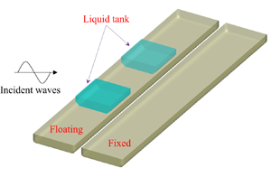
The experimental set-up is illustrated in figure 1. Two identical rectangular side-by-side barges are in a fixed–free arrangement. Vessel no. 1 is freely floating and equipped with two identical prismatic tanks with liquid inside, whereas vessel no. 2 is fixed to the gantry. Dimensions of barges and the tanks’ arrangement for the experiments are exhibited in table 1. Centre of gravity, mass and gyration radii of the floating vessel are presented in tables 2 and 3. In Table 3, ‘frozen’ (note that ‘frozen’ liquid is not the same as in the completely filled case) means the liquid mass is accounted for, while ‘empty’ indicates that the liquid in tanks is excluded.

Figure 1. Sketch of two barges in a side-by-side configuration with sloshing tanks on barge no. 1. (a) Top view and (b) sectional view.
Table 1. Dimensions of the barge and tank deployment. Unit: metre.

Table 2. Gravity centre of the floating vessel.

Table 3. Mass and gyration radii of the floating vessel.

To excite vessel motions, white noise-type waves ranging from  $0.6$ to $3.0$ s with significant wave height of 14 mm and a random phase distribution are generated. Water waves are generated both with and without barge models in place for wave calibration. By changing the direction of the barge models, different wave headings are achieved. By calculating the ratio of cross-power spectral density of the time histories with and without barge models, the response amplitude operators (RAOs) of vessel motions are obtained. In addition, an inclination test has been performed to calibrate the vessel's metacentric height and to check the centre of gravity, and a free decay test was also conducted to determine the viscous roll damping for the floating vessel.
4. Results and discussions
In numerical implementations, each rectangular barge is discretised into  $2144$ quadrilateral panels, and the dissipation surface located on the free surface in between two vessels has $320$ panels. When sloshing is accounted for, each tank is discretised into $3000$ panels over the mean wetted tank surface and free surface, as illustrated in figure 2. A convergence test has been carried out, and it demonstrates that the present mesh yielded converged results. A damping term is introduced on the free-surface condition imposed between the two barges to suppress any unrealistic response near the gap resonance conditions. The viscous coefficient associated with the damping term, obtained via calibration with experimental measurements, is $\nu _0=0.04$. To incorporate viscous effects on roll motions, an external roll damping, which is determined by the free decay tests, is included in the motion (2.16). The roll damping for vessel no. 1, which is freely floating, is $\tilde {B}_{4,4}^{1,1}=3.75$ N m s for frozen cases, and is $\tilde {B}_{4,4}^{1,1}=7.01$ N m s for liquid sloshing cases.

Figure 2. Mesh model with  ${\rm 2144}$ panels on each barge (grey), ${\rm 320}$ panels on the dissipation surface (purple) and ${\rm 3000}$ panels on each tank (gold). Barge no. 1 (free floating) is shown here on the left with the liquid tanks.

Figure 3. Motion RAOs of barge no. 1 of a fixed–free deployment without liquid sloshing effects under beam sea excitation.

Figure 4. Motion RAOs of barge no. 1 of a fixed–free deployment without liquid sloshing effects under head sea excitation.

Figure 5. Motion RAOs of barge no. 1 of a fixed–free arrangement with liquid sloshing effects under beam sea excitation.
4.1 Without liquid sloshing
Wave induced motions of side-by-side vessels in a fixed–free deployment without liquid sloshing effects are first considered. Figure 3 depicts the RAOs of vessel no. 1 in the beam sea condition ( $\beta =90^{\circ }$). In this scenario, vessel no. 1 is on the weather side, while vessel no. 2 is on the lee side. The translational motions are normalised by the wave amplitude $a$, and rotational ones are by incident wave steepness $k_0a$. Numerical results with and without energy dissipation effects together with the experimental measurements are presented. Because of the symmetric set-up, sway, heave and roll motions are excited, and only odd modes are excited when gap resonance occurs. For numerical results with and without energy dissipation effects, the apparent discrepancy appears near the frequency at which the gap resonance occurs. When the energy dissipation effect is excluded, the computed motion response near the gap resonance frequency at $\omega \sqrt {L/g}\approx 4.6$ is significantly greater than in the experiments. When the dissipation effect is accounted for, the computed motion response is realistic, and satisfactory agreement between the numerical results and experimental measurements is obtained. When the roll resonance occurs near $\omega \sqrt {L/g}\approx 3.5$, an apparent drop in sway and heave motions is witnessed, indicating there is energy transfer between different motion modes.
The motion RAOs of vessel no. 1 under head sea excitation ( $\beta =180^{\circ }$) are depicted in figure 4. Numerical results with and without dissipation effects as well as experimental results are presented. Due to the presence of the stationary vessel in place, symmetry no longer exists, and all of six degrees of freedom motions are excited. The inline motions, including surge, heave and pitch, are primarily driven by the excitation of incident waves, and the motion amplitudes do not vary much even when gap resonance occurs. There is a clear drop in surge and heave motions when the incident wavelength is approximately equal to the barge's length at $\omega \sqrt {L/g}\approx 2.5$, because the wave crest and wave trough yield equal but opposite pressure forces, resulting in substantial cancellations. However, the lateral motions consisting of sway, roll and yaw are excited by waves scattered by vessel no. 2, which is stationary. The wave induced motions reach maximum when the half-wavelength equals the barge's length at $\omega \sqrt {L/g}\approx 1.77$. In this scenario, waves forces are only induced in one direction, and there is little cancellation. When the gap resonance occurs, there is thus an appreciable increase in the sway motion, and the numerical model without energy dissipation apparently overpredicts the motion responses. When the energy dissipation is included, the numerical results are realistic. In general, the agreement with experimental measurements is good except at low frequencies. At a low wave frequency, the corresponding wavelength is large, and the efficacy of wave absorption in the basin facility is less satisfactory. Therefore, the deviation from the experiments is expected.
4.2 With liquid sloshing effects
Now, we consider liquid sloshing effects on motions of a floating barge alongside a fixed barge. To determine the natural frequencies of liquid sloshing in a tank with chamfers, we adopt Rayleigh's quotient together with the variational theorem (Reference Faltinsen and TimokhaFaltinsen & Timokha, 2014)
 \begin{equation} \omega_{i,j} \approx \tilde{\omega}_{i,j} \sqrt{ 1- \left. \iiint_{\delta Q}(\nabla\varphi_{i,j})^2\,\mathrm{d} Q \right/ \left(\frac{\tilde{\omega}_{i,j}^2}{g}\iint_{\varSigma^F} \varphi_{i,j}^2 \,\mathrm{d} S\right)}, \quad\text{with } i + j\ge 1, \end{equation}
where  $\delta Q$ denotes the volume chamfered, $\tilde {\omega }_{i,j}$ are the natural frequencies without chamfers and $\varphi _{i,j}$ are natural modes given by
 \begin{equation} \varphi_{i,j} = \frac{\cosh[k_{i,j}(z + d_{T})]}{\cosh(k_{i,j}d_{T})} \cos\left[k_{x}\left(x + \frac{L_{T}}{2}\right)\right] \cos\left[k_{y}\left(y + \frac{B_{T}}{2}\right)\right], \end{equation}
with
 \begin{equation} k_{x} = {\rm \pi}i/L_{T},\quad k_{y} = {\rm \pi}j/B_{T} \quad\text{and}\quad k_{i,j}^{2} = k_{x}^{2} + k_{y}^{2}. \end{equation}
In (4.1), the first and second indices  $i$ and $j$ correspond to modes in the longitudinal and transverse directions, respectively. In the present study, the natural frequencies of liquid sloshing in longitudinal and transverse motions are $\omega _{1,0}\sqrt {L/g}\approx 3.74$ and $\omega _{0,1}\sqrt {L/g}\approx 3.88$, respectively.
Figure 4 depicts the motion RAOs of the floating barge with liquid sloshing effects under beam sea excitation ( $\beta =90^{\circ }$) with vessel no. 1 on the weather side and vessel no. 2 on the lee side. The results without sloshing effects presented in figure 3 are also included, and comparison is made with the experiments. In this scenario with liquid sloshing effects, the numerical results are in general good agreement with the experimental measurements, except the roll motion. The peak value at roll resonance is appreciably lower than in the experiments. When sloshing effects are accounted for, the frequency of roll resonance is reduced because of the contribution of the added moment of inertia due to liquid sloshing. Moreover, the roll motion amplitude with sloshing effects is reduced compared with the frozen case. When the wave frequency is close to $\omega _{0,1}$, the roll motion amplitude is very small because of a large roll added moment of inertia caused by liquid sloshing in proximity to the natural frequency. For sway motions, the Stokes natural frequency at which the vessel motion is small is apparently greater than $\omega _{0,1}$, and the disagreement is due to the presence of vessel no. 2 resulting in large variation in the sway added mass of vessel no. 1. Within the framework of linear potential-flow theory, the heave motion cannot excite liquid sloshing in tanks (Reference Faltinsen and TimokhaFaltinsen & Timokha, 2009). However, we still observed the difference from the results without the liquid sloshing effects, and thus the difference is due to the coupling of motion modes.
The motion RAOs of vessel no. 1 with liquid sloshing effects in internal tanks under the head sea excitation are depicted in figure 6. The results with/without liquid sloshing effects are presented, and comparison is made with the experimental measurements, with generally satisfactory agreement. As with figure 4, all of the six degrees of freedom of body motions are excited. In this scenario, the liquid sloshing in internal tanks has negligible effects on heave, pitch and yaw motions, whereas they produce appreciable influences on surge, sway and roll motions. In sway and roll motions, the corresponding motion amplitudes are diminishing near the Stokes natural frequencies of  $\omega _{1,0}\sqrt {L/g}\approx 3.74$ and $\omega _{0,1}\sqrt {L/g}\approx 3.88$, respectively, at which the added mass due to liquid sloshing is large. In addition, the roll motion amplitude reaches a maximum near $\omega \sqrt {L/g}\approx 4.1$.

Figure 6. Motion RAOs of barge no. 1 of a fixed–free arrangement with liquid sloshing effects under head sea excitation.
To further investigate the motion characteristics, figure 7 depicts the mass ratio with/without liquid sloshing effects as a function of the non-dimensional frequency, where the mass ratio is defined as
 \begin{equation} \mathcal{M}_{j} = \frac{M_{j,j}^{1,1} + A_{j,j}^{1,1} + \hat{A}_{j,j}^{1,1}}{M^{1,1}_{j,j}}. \end{equation}
When the liquid sloshing is accounted for,  $M^{1,1}_{j,j}$ denotes the mass with frozen liquid. It is observed from figure 7 that the liquid sloshing effects have negligible influences on the mass ratio in heave, pitch and yaw motions, indicating that the wave induced motion is barely affected. There is a large variation in mass ratio near the frequency at which gap resonance occurs. On the contrary, the liquid sloshing significantly affects the mass ratio in surge, sway and roll motions due to an apparent difference of mass ratios with and without sloshing effects. At the Stokes natural frequency $\omega _{1,0}$ or $\omega _{0,1}$, the mass ratio with sloshing effects in these motion modes has a sharp variation from positive to negative compared with that without sloshing. By graphically determining the point at which the mass ratio vanishes, one can determine the non-Stokes natural frequency (Reference Faltinsen and TimokhaFaltinsen & Timokha, 2021) plotted by a hollow circle in the figure. The determined non-Stokes natural frequency is consistent with the frequency at which motion amplitude reaches a maximum in figure 6. Therefore, the influence of the liquid sloshing on wave induced motion can be expounded by the influence of liquid sloshing on the mass ratio.

Figure 7. Mass ratio of the floating barge in different motion modes. Vertical dashed line corresponds to the Stokes natural frequency of liquid sloshing in internal tanks.
5. Concluding remarks
In this study, we have investigated the interactions between water waves and side-by-side barges in a fixed–free deployment with/without liquid sloshing effects. A potential-flow model to deal with interactions among water waves, multibody system and liquid sloshing in internal tanks is set up, and numerical implementation is realised by means of the boundary element method. Physical experiments have been carried out both with and without liquid sloshing effects, providing reference results. The satisfactory agreement between numerical results and experimental measurements indicates that the classical linear potential theory together with a dissipation surface is able to unravel the primary physics of complex interactions among water waves, the multibody system and liquid sloshing in internal tanks.
The influence of liquid sloshing in internal tanks on body motions can be quantified by its influence on the mass ratio. When the mass ratio is strongly affected by the liquid sloshing in the tanks, so is the wave induced motion. In the vicinity of the Stokes natural frequency of sloshing, the body motion is diminishing as a result of a large added mass due to sloshing. By making the mass ratio vanish, one can determine the non-Stokes natural frequency at which the body motion reaches a maximum.
Despite good agreement in the present study, it should be noted that the linear potential theory cannot elucidate the primary physics in some cases. One exception is liquid sloshing in an upright circular tank (Reference Liang, Santo, Shao, Law and ChanLiang, Santo, Shao, Law, & Chan, 2020; Reference Liu, Shao, Chen and LiangLiu, Shao, Chen, & Liang, 2022; Reference Tan, Shao and ReadTan, Shao, & Read, 2019), in which non-planar waves occur due to modal interactions. In this case, the nonlinearity of sloshing flow must be accounted for.
Acknowledgements
Authors are grateful to Drs D.P. Vieira and K.Y. Kang for the support in the experiments.
Declaration of Interests
The authors declare no conflict of interest.
Funding Statement
This work is supported by the National Research Foundation, Singapore and Singapore Maritime Institute under the Maritime Transformation Programme White Space Fund (Centre of Excellence for Autonomous and Remotely Operated Vessels (CEAOPS), Project ID SMI-2019-MTP-01) and A*STAR Science and Engineering Research Council, grant no. 172 19 00089 under the Marine & Offshore Strategic Research Programme (M&O SRP).
Author Contributions
H.L. worked on the theory and numerical code. X.L. and K.H.C. oversaw the experiments. P.C.M. conducted experiments. Y.S.C. supervised the project. H.L. wrote the text.
Data Availability Statement
Raw data are available from the corresponding author (H.L.).
Ethical Standards
The research meets all ethical guidelines, including adherence to the legal requirements of the study country.


 Open access