


Introduction
The Blue Ice Drill (BID) is a large-diameter, agile electromechanical coring drill developed by the Ice Drilling Design and Operations group of the University of Wisconsin-Madison to take large-volume, near-surface, contamination-free ice samples. Ice cores of 241 mm diameter can be drilled to depths of 30 m. The BID leverages design features of numerous existing electromechanical ice-coring drills (Reference Schwander, Rufli, Rado and BeaudoingSchwander and Rufi, 1988; Reference Proenza, Kelley, Koci, Sonderup and WumkesProenza and others, 1990; Reference JohnsenJohnsen and others, 2007). The drill consists of a cutter head, inner and outer barrel assembly and motor/reducer section. Reaction torque is applied from the surface via a sectioned torsion stem of thin-walled, aluminum tube. The subsurface equipment is supported by a tripod, winch, rope, power cable and motor control. Figure 1 details the major components of the BID system.

Fig. 1. Schematic view of the major components of the BID system.
The following is an example of a typical coring operation. (1) Lower drill to a point a short distance above surface. (2) Turn on the drill motor. (3) Belay the drill rope to control descent speed for smooth cutting. (4) Continue coring to no more than 1.15 m maximum core length. (5) Use winch to break core and raise sonde to surface. (6) Run drill motor in reverse to remove chips. (7) Break barrels and remove core with push pole. (8) Check and clean cutter before repeating for additional core.
The BID includes a core recovery tool (CRT), described below, as an optional part of the system deployed to break and recover samples by tipping the core. It is a device similar to that used in the 12 in (∼30.5 cm) CRREL (US Army Cold Regions Research and Engineering Laboratory, Hanover, NH) drill, Big John (Reference Rand and MellorRand and Mellor, 1985).
The design of the BID system is constrained by specific science and operational requirements. These include specifications for core diameter, core length, core quality, production rate, hole depth, inclination, sample contamination, system weight and transportability, and operating temperature. Table 1 lists the science requirements for the development of the BID.
Table 1. Science requirements for the BID system

Subsystems
Cutter head
The cutter head is a stainless-steel ring attached to the down-hole end of the core barrel. It serves as an attachment point for the cutters, penetration shoes and core dogs and initiates the transport of ice cuttings upwards into the barrel assembly. Rotation is imparted to the cutter head by the motor/reducer section via the core barrel. The cutter head assembly is detailed in Figure 2.
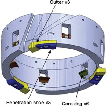
Fig. 2. Model view of the BID cutter head assembly.
Three cutters are held in the cutter head spaced 12° apart. Each cutter features a 30° rake angle (off vertical plane) and 7° clearance angle (off horizontal plane). Two widths of cutters are available: 23.3 mm thin kerf (241 mm core, 288mm hole) and 25.8 mm wide kerf (240mm core, 291 mm hole). Hardened tool steel is used for the standard cutters, while carbide-tipped stainless-steel cutters are used in dirty ice conditions. The descent rate of the drill is controlled by three penetration shoes. Shoes of various sizes are available and easily interchanged to allow adjustment from 0.75 to 21 mm pitch (0.25–7.0mm depth of cut per cutter). A plastic cover snaps to the bottom of the cutter head to protect the cutters and operator during core/cuttings removal.
Six hardened, tool-steel core dogs (sharp-tipped, teardrop-shaped pawls) of three different lengths (12.7, 15.2 and 17.8 mm intrusion depths) are available to facilitate core break and retrieval under varying ice conditions. Each is installed on a dowel-pin axle and spring-loaded to allow the core dogs to retract into the cutter-head annulus during coring. To retrieve an ice core the drill is pulled upward, causing the core dogs to engage and creating a propagating fracture across the ice core. The core dogs then support the core as the drill is brought to the surface.
Barrel assembly
The BID utilizes a double barrel design with a rotating, inner core barrel and a stationary, outer barrel (Fig. 3). Each barrel is composed of mandrel-laid fiberglass epoxy tubing which is exceptionally light, strong, tough, round and straight. In this application, the strength of the fiberglass barrels has proved adequate, even supporting the full load of core break. Greenhouse melting of chips occurred in the first field season due to the transparent properties of the material, but this issue was effectively addressed by painting the outer barrels white. The core barrel features three helical flights to transport ice cuttings upwards from the cutter head as the assembly is rotated within the outer barrel. The flights are cast in-place on the core barrel from glass-reinforced epoxy resin. The efficiency of cuttings transport is increased by five equally spaced, stainless-steel strips attached axially along the inner surface of the outer barrel with adhesive and flat-head screws. Cuttings are transported to the top of the core barrel where three windows in the tubing allow the cuttings to collect on top of the core being drilled. A plastic plug is suspended within the core barrel and used to segregate the ice cuttings from the core, when desired. Three barrel-stabilizing pads, located at the top of the outer barrel, are shimmed to the borehole diameter to keep the drill tracking straight.

Fig. 3. Model view of the BID barrel assembly.
Motor section
Power for cutting ice and transporting cuttings is provided by a custom a.c. induction motor rated to 1.9 kW at 1730 rpm. Figure 4 shows details of the BID motor/reducer section. A two-stage, planetary gear reducer with a reduction of 28 : 1 provides 60 rpm at the cutter head for a motor speed of 1680 rpm. A spline shaft and nut connect the gear reducer output to a drive plate with three bayonet-style, lock-pin assemblies for quickly attaching/removing the core barrel. The core barrel drive plate is supported by a slewing bearing designed to carry the full axial and moment loads imparted to the drill barrel assembly. A rubber shaft seal between the motor housing and core-barrel drive plate provides secondary containment for lubricating fluids present in the motor section.

Fig. 4. Cutaway model view of the BID motor/reducer section with the slide-hammer assembly.
The motor and reducer are housed within an aluminum and stainless-steel enclosure rigidly connected to the outer barrel. Two versions of this housing exist: a model equipped with a load-triggered slide hammer for core breaks and a model without the slide hammer. The slide-hammer assembly consists of a two-piece, splined housing with 82 mm of axial travel. Up to six neodymium magnets attracted to an iron plate hold the assembly closed with a maximum of 6.7 kN of force. Magnets can be removed to tune the actuation force to specific coring conditions. The motor and gear reducer are attached to the upper portion of the slide-hammer assembly, giving a total moving mass of ∼56 kg (DEEP version with AT Section). Applying axial force, in excess of the holding force of the magnets, causes the upper slide-hammer assembly to actuate to the extended position against a rigid stop in a fraction of a second. This imparts an impulse force to quickly set the core dogs and propagate a crack across the ice core. The slide hammer is extremely effective for producing highly predictable, repeatable and clean core breaks. The second motor-housing version is without the slide hammer, resulting in a significantly lighter, shorter motor/reducer section (46 kg, 659 mm vs 78 kg, 903 mm). It is used in conjunction with the CRT.
The down-hole portion of the drill (sonde) is suspended via a rope attached to a swivel on the motor section top plate. The top plate also contains a mount to attach the torsion stem extensions, recovery loop, electrical connector mount, and, on the slide-hammer version, breather plugs to vent the interior during actuation.
Core recovery tool
A separate device, the CRT, is used for core break and retrieval at shallow depths (Fig. 5). Using the CRT saves the time required to break the barrels of the drill, remove core and reassemble the drill. While the CRT is being deployed, chips in the barrels are quickly dumped and the sonde is readied to return for the next core. The CRT consists of a 1m length of fiberglass core barrel with three small core dogs mounted in centering housings at the bottom. A tilt mechanism is attached to the top of the core barrel with three bayonet-style lock-pins. The tilt mechanism transforms a vertical force from the suspending rope to a horizontal force via a cam profile/follower actuating a spring-loaded piston. A vertical force of ∼700 N is sufficient to actuate the tilt mechanism, breaking the core at the base. The core dogs engage in the core to resist the vertical actuation force and hold the core for retrieval to the surface. A 300 mm long core barrel is used to break cores shorter than ∼500 mm.

Fig. 5. Interior model view of the CRT tilt mechanism.
Electrical and control
Electrical power requirements for the BID system are supplied by a single 3.5 kW generator (240 V, 20 A continuous). Power is delivered to a custom control box via a 30 m, 10/4 electrical cord. A variable frequency drive (VFD) converts the 240 V, single-phase output of the generator to three-phase power to operate the drill motor, while 120 V, single-phase service is supplied to two standard outlets on the control box to power the winch motor and accessories. The VFD provides for near-constant torque at all speeds, up to the motor nameplate rpm, and soft-starts the drill motor to limit inrush current. A 35 m, 16/4 electrical cord on a spring-energized, retracting cord reel supplies power down-hole to the drill motor. The drill motor electrical cord terminates in a watertight, strain-relieved cord grip in the motor section top plate.
The faceplate of the control box contains controls for on/off, emergency stop, rotation direction, rotation speed, local/remote, and VFD parameters. A motor load gauge and digital screen for viewing VFD settings and inputs/outputs are also located on the faceplate. Load resistors regulated with a thermostat provide heat to keep the internal temperature of the control box above 0°C. Drill motor rotation is controlled either with local controls on the faceplate or with two interlock switches on the torsion stem handles used by the operator to anti-torque the drill.
Support structure
The drill sonde is suspended from a 5.3 m tall tripod constructed of aluminum pipe segments connected with coupler sleeves. The tripod contains two adjustable-length legs to help center the hanging drill on uneven surfaces. Two sheaves are mounted on a single axle in the tripod apex frame, allowing both the drill and CRT to be suspended simultaneously via separate lines. A commercial capstan winch with a maximum pulling force of 26.7 kN is mounted in-line with the fixed-length tripod leg. The winch is driven by a right-angle, two-speed electric drill motor (120V, 13 A) controlled with a foot switch. Low-stretch ropes of 13 and 19 mm diameters are used for the CRTand drill, respectively. Each leg terminates in a hinged, triangular footplate with holes for ice screws to affix the tripod to the ice surface. The tripod is designed to safely support dynamic loads and the maximum cable tension at core break while minimizing weight and bulk for transportability. For projects requiring frequent local drill moves over relatively flat terrain, the tripod is mounted on a custom HDPE plastic platform sled.
Operation And Performance
The BID is operated by a minimum of two operators. A winch operator controls descent and ascent of the drill and CRT by tailing the respective ropes on the capstan winch. The winch operator also manipulates the control box to select drill rotation direction and local or remote operation and monitors drill motor power. A second operator antitorques the drill by means of two handles attached to either a barrel clamp for shallow coring or the uppermost torsion stem section for deeper cores. The drill operator controls drill rotation by means of the interlock switches on the antitorque handles and adds or removes torsion stem sections as the drill is tripped in or out of the hole. Both operators assist in removing and handling ice cores. The speed of coring is greatly increased with the addition of a third operator to handle core-processing duties.
Figure 6 shows the BID system in use on Taylor Glacier, McMurdo Dry Valleys, Antarctica. Selected performance values of the current version of the BID are given in Table 2. Operation of the BID within the current depth limit is most efficiently accomplished by retrieving cores with the CRT. In this operational mode, the core dogs are removed from the cutter head, allowing the core to be drilled and left in the hole, still attached to the ice at the base, when the drill is withdrawn. The CRT is then tripped down the hole to retrieve the core. On the surface the drill motor is run at slow speed in reverse to empty ice cuttings from the helical flights, and the cuttings are emptied from the core barrel by means of a removable bottom plate in the plastic plug that separates the cuttings from the core. Doing so eliminates the need to disconnect the core barrel from the drill sonde between runs. The additional time required to trip the CRT into and out of the hole is insignificant, at shallow depths, compared to the time saved with reduced core barrel handling.
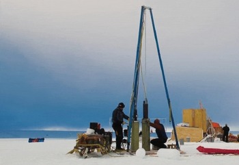
Fig. 6. The BID coring at the surface on Taylor Glacier. Notice the anti-torque handles attached to the outer barrel via a clamping device for near-surface coring. Photo by Robb Kulin.
Table 2. Performance values for the BID system
BID-deep
A variety of modifications to the BID system have been completed in response to requests from the scientific community for large-volume samples from depths beyond its original capability. The original rope and electrical cord was replaced with a 9.60 mm diameter steel electromechanical cable. The cable includes seven 20 AWG copper conductors and has a breaking strength of nearly nine times the 6.7 kN core break tension. 220 m of this cable are spooled on an aluminum winch drum featuring a grooved drum to facilitate level-winding. The winch is powered by a 4 kW gear motor with a 119:1 helical-bevel gear reduction capable of developing a maximum cable tension of 18 kN. A new crown sheave assembly with a 457 mm diameter sheave wheel attaches to the original tripod legs. The clearance under the tripod is increased to 5.6 m by adding 29 cm extensions to each tripod leg. Tripod leg stiffness has been maintained by linking the legs together with three Tie Rods. The original capstan winch can still be used to operate the CRT, or other down-hole tools, via an accessory pulley mounted below the crown sheave assembly. Figure 7 shows the solid CAD model of the BID-Deep system.

Fig. 7. Isometric view of the recently developed Deep additions to the BID system.
The three-phase a.c. induction motor on the winch gear motor is controlled with a VFD. A braking transistor module and resistive load bank allow the winch to safely control the weight of the sonde during lowering. Additional braking is provided by a 40 Nm shaft brake mounted on the winch motor and controlled through the VFD. Speed and direction controls for the winch are housed in a weather-tight, corded pendant. Fine ascent/descent control of the sonde is accomplished via a hand-wheel mounted directly to the motor shaft. A manual motor brake override switch mounted on the winch motor disengages the brake during hand-wheel operation. E-stops are located on both the pendant and winch motor body. The BID-Deep system is powered by a 240 V, 30 A, single-phase electrical source.
Upgrades to the original BID motor section allow the drill to anti-torque cutting forces via five leaf-spring skates mounted to an assembly surrounding the motor can. The electromechanical cable connects to a bearing-supported shaft in the motor section with a commercial mechanical cable termination. Attached to the bottom of the bearing shaft is a four-channel electrical slip-ring which transmits power from the cable to the drill motor while allowing the sonde to rotate independently of the cable. The load-triggered slide hammer is maintained in the Deep version of the drill. Early failures of drill motors have been attributed to shock during operation of the slide hammer. Modifications to shock-strengthen the drill motor have been implemented including the addition of steel support strips in the motor housing and the change to bearings with improved thrust load capacity. No additional failures have been seen since these modifications were implemented.
For depths below ∼30 m, core retrieval with the CRT becomes inefficient, due to the longer tripping times involved. Therefore the sonde itself is utilized for core retrieval. A tapered collet with flexible fingers is used for low-density firn cores. Core dogs, as described above, are used in place of the collet as the density of the firn/ice increases.
Applications
The BID system was tested in a cold-room facility at the CRREL in June 2010. It was first deployed to the field in November 2010 in support of a two-season scientific project on Taylor Glacier. During the first drilling season, a total of 560 m of core were recovered from 34 holes, the deepest of these being 21 m, in ∼33 (8 hour) shifts. Core recovery was 100%, with generally excellent core quality. Following this initial season a variety of minor improvements were made to the drill system.
The second season at Taylor Glacier yielded marked improvements in drilling efficiency. During the 2011/12 season, 64 holes were drilled in 32 shifts, for a total of 931 m of core recovered. The maximum hole depth was ∼26 m.
The drill system was next deployed to a site near Summit Station, Greenland, for a firn-coring test in preparation for BID-Deep modifications. During this test, a 24 m deep hole was drilled in 23 runs. Drill performance was overall satisfactory, although several problems were encountered that required design modifications. Primary among these were shallow firn-core recovery and slide-hammer impact damage to the motor section.
The BID system was again deployed to Taylor Glacier for the 2013/14 field season. Approximately 1355 m of core were recovered in 1432 drill runs from 151 separate holes. This required 34 days to complete, with two drill shifts per day for the majority of the season. Excellent coring efficiency was achieved this season, in part due to the use of the antitorque skates on the motor section (see BID-Deep above).
The next scheduled field season for the BID system begins in May 2014 near Summit Station. This deployment will include the full BID-Deep system.
Acknowledgements
IDDO benefits from the exceptional support of many organizations in developing new drill systems, and this development effort was no exception. All merit acknowledgement and our sincere appreciation. In particular, we thank the members of the Ice Drilling Program Office (IDPO) and the IDDO Technical Advisory Board (TAB) for ongoing advice and assistance; University of Wisconsin–Madison, particularly the Space Science and Engineering Center, for providing exceptional support; and the Arctic and Antarctic support contractors and the US National Science Foundation (NSF) Office of Polar Programs for making it all possible. This work was supported under NSF Cooperative Agreement OPP-0841135 and CA 1327315.


