


1. INTRODUCTION
In the modern hypercompetitive market, companies are pushed to fulfill the customers’ expectations by offering new products and services as well as a wide range of product variants (Ulrich & Eppinger, Reference Ulrich and Eppinger2012). However, assessing the feasibility, the sustainability, and the profitability of the proposed solutions is fundamental to be a healthy company that makes profit. In this context, designing new product variants and redesigning the existing products in order to efficiently offer a wide range of solutions is crucial to quickly introduce new functionalities and adapt the product features to the changing customers’ needs in an efficient and flexible manner, controlling time, cost, and life cycle sustainability. It consists of merging technical issues (i.e., how components share direct interfaces with adjacent components, how interfaces may propagate to nonadjacent components in the product, and how components may act as bridges among other components through their interfaces) with business issues (i.e., how to make complexity manageable, how to enable parallel work, and how to accommodate future uncertainty; Baldwin & Clark, Reference Baldwin, Clark, Braha, Minai and Bar-Yam2006).
Product variants’ configuration generally involves marketing, design, engineering, and production departments. Marketing staff analyzes the market segments to be addressed and identifies the customers’ needs. After that, designers conceive the new product concept to be offered and define the brief as well as the expected functionalities. Subsequently, designers and engineers define the so-called functional requirements and how to technically realizing the desired functions. Finally, engineering and production departments deal with the product variants generation and the configuration of the feasible solutions (Jiao & Zhang, Reference Jiao and Zhang2005; ElMaraghy et al., Reference ElMaraghy, Schuh, ElMaraghy, Piller, Schönsleben, Tseng and Bernard2013). In this context, modular product platforms let companies offer a variety of products in an efficient way by providing significant time and cost saving, as demonstrated by numerous studies over the years (Farrell & Simpson, Reference Farrell and Simpson2003; Frenken & Mendritzki, Reference Frenken and Mendritzki2012; Wan et al., Reference Wan, Evers and Dresner2012). Modular product platforms are able to support the development of product families, composed by a set of product variants on a common product architecture, using shared resources and reducing the involved resources. Thanks to assets sharing, both cost savings and operational benefits can be achieved (e.g., about sourcing, manufacturing, and quality control; Otto et al., Reference Otto, Hölttä-Otto, Simpson, Krause, Ripperda and Moon2016). Furthermore, a product family allows addressing a set of diversified market segments while maximizing the production efficiency through the standardization of parts and solutions (Jiao et al., Reference Jiao, Simpson and Siddique2007).
In order to create consistent product variants and to efficiently manage their combination by respecting technical, feasibility, and economical constraints, a proper functional model of the desired product family has to be defined. Therefore, in order to save time, resources, and then money, iterations should be minimized by the adoption of functional-based approaches able to manage the development processes in a more straightforward way by limiting costs and efforts. In this context, adoption of structured functional-based models in industrial practice is still limited due mainly to the difficulties in defining the most proper function-based approach for the specific context of application, and the necessary effort required to properly represent the product knowledge, model the functional solutions, and generate the variants on the basis of the product functions. There are various methods to support modular design for industrial products, from axiomatic design (AD), to design structure matrix (DSM), functional modeling (FM), modular function deployment (MFD), and variant mode and effects analysis (VMEA), which can be also used in combination with an architecture development process (Stjepandić et al., Reference Stjepandić, Ostrosi, Fougères, Kurth, Stjepandić, Wognum and Verhagen2015). While AD and DSM are mainly oriented to technical issues and mapping of the relations among product components, FM is a particularly useful method to focus on product functions for structuring the product into modules, to clarify the understanding of a design problem, and to serve as core to the modular solution. The modular form of the product depends on the form of chains of connected elementary subfunctions. In addition, the MFD approach facilitates the development of a robust production program that is easily adaptable to the varying requirements by introducing a set of dedicated criteria (i.e., module drivers), which compile a business strategy into a framework for modular product design. It is a good tool to link technical and business issues. Finally, VMEA can help to depict the impacts of product variants in the enterprise units from the definition of the product program to distribution, including cost evaluation.
The present work adopts FM as the primary approach for product structuring, and a combination of MFD and VMEA to define a function-based model to support product variants’ design and redesign according to a modular framework. The main goals of the proposed model are the following:
-
1. to offer a robust framework to define a reliable product representation founded on functional analysis to represent functional, modular, and multiple product architectures;
-
2. to manage and represent the product knowledge to be easily searched and retrieved for design purposes, by an agent-based approach; and
-
3. to support the development of an IT platform for product redesign and variant configuration by considering the product life cycle issues, mainly cost and sustainability.
As a result, the authors incorporates the developed model into an IT multiuser platform, composed of knowledge management engine and different modules, taking care about FM, product configuration, cost estimation, and life cycle assessment (LCA). It is able to enhance searching and reusing of existing configurations limiting the required changes; to effectively represent industrial products from a functional, modular, and architectural point of view; to easily assess the impact of the changes introduced by a new variant in customizable design contexts; and to accurately estimate costs and environmental impacts of the new configured solutions.
2. BACKGROUND ON FUNCTION MODELING IN MODULAR PRODUCT VARIANT DESIGN
Product function modeling consists of the representation of the individual operations and transformations that contribute to the overall performance of the product itself and the mapping of the relations between the product elements, which are parts, components, and subassemblies that ultimately implement the product's functions. The product architecture refers to the organizational structure of an artifact, and more specifically to the arrangement of its functions; it maps the functional elements of the product and describes how they are arranged into physical blocks (Ulrich & Eppinger, Reference Ulrich and Eppinger2012). A product family includes a set of variables, features, or components that, in time, do not change from product to product, and others that instead vary from product to product. Within a given family, the modification of the product features can be achieved through scaling, addition, substitution, or exclusion of modules (Pahl et al., Reference Pahl, Beitz, Feldhusen and Grote2007). The product architecture and the function modeling both have an obvious strong impact on the development of the relative product family and on the ability to generate variants (ElMaraghy et al., Reference ElMaraghy, Schuh, ElMaraghy, Piller, Schönsleben, Tseng and Bernard2013). Furthermore, variants generation also affects the company business strategy as well as production time and costs, and the overall process sustainability.
According to Hölttä and Salonen (Reference Hölttä and Salonen2003), there are few consolidated modularization methods: the function structure heuristic method (Stone et al., Reference Stone, Wood and Crawford2000), the clustering of a DSM (Pimmler & Eppinger, Reference Pimmler and Eppinger1994), and the MFD method (Ericsson & Erixon, Reference Ericsson and Erixon1999). In particular, the MFD method (Ericsson & Erixon, Reference Ericsson and Erixon1999) provides a systematic evaluation of technical solutions for a given product, based on the functional product structure. It is based on the quality function deployment methodology, which is expanded with the modularity concept by introducing dedicated criteria (“module drivers”), which measure the product feasibility from certain viewpoints (e.g., cost, sustainability, and productivity). Thanks to a proper matrix, it provides a procedure for investigating opportunities of integrating multiple functions into single modules by using the interface matrix, changing the expected assembly sequence, or changing the modules’ features. The expected effects of the redesign can be estimated and an evaluation can be provided for each modular concept. Recently, Borjesson and Hölttä (Reference Borjesson and Hölttä2014) have proposed an integration of the DSM and MFD approaches in order to balance the two and take into account both interactions and company portfolio strategies. In addition, the VMEA can be used to optimize product modularity by the assessment technical and economic criteria of product variety diversity, integrating business units such as marketing, product program planning, product development, production, and distribution (Stjepandić et al., Reference Stjepandić, Ostrosi, Fougères, Kurth, Stjepandić, Wognum and Verhagen2015).
After product modular structuring, configuration is strategic to meet the target of the mass customization by satisfying different customer needs with customized products, based on variants combinations. A good product configuration should maintain the efficiency and cost of mass production (Pine, Reference Pine1993). It is based on combining instances of different component types taking into account restrictions, constraints, and compatibility issues (Felfernig et al., Reference Felfernig, Hotz, Bagley and Tiihonen2014). Component types refer to sets of alternative components, namely, instances, and they are characterized by attributes. Constraints are restrictions of the way in which different components can be combined with each other. A configurable product is the result of the development of the solution space that identifies the product properties for which customer needs diverge. Therefore, a configurable product requires the design of a family of products, where a specific configuration specifies one of the possible product variants (Tiihonen, Reference Tiihonen2014).
In this context, product variants are often defined by engineering changes (ECs), especially on existing products, to adapt the existing product businesses to the rapid evolution of the market. In view of this, ECs represent a key aspect of innovation, as they allow more variants to satisfy the demand of specific market niches. ECs and their propagation could be assessed at various stages of the design process, but their estimate should be conducted as soon as possible to reduce costs that will inevitably increase at the end of the design process (Koh et al., Reference Koh, Caldwell and Clarkson2012). In literature, numerous examples and discussions exist about different change propagation linkages. Some of these are focused on the physical domain, such as linkage between components forming the product architecture, and others, on the functional domain (e.g., function–form relationship). ECs’ management is fundamental for product variant configuration. Clarckson et al. (2004) contributed in modeling ECs and their propagation during the design and development of a complex product, while Kilpinen et al. (Reference Kilpinen, Eckert and Clarkson2009) developed a method to assess the consequences of ECs in the aerospace industry. Furthermore, Kocar and Akgunduz (Reference Kocar and Akgunduz2010) developed a probabilistic analysis of propagations by observing the implicit linkage between product components by a virtual platform for collecting ECs and identifying the list of components that were affected in the past by similar changes. EC propagation has been also studied through a network of physical components and their related coupling strengths (Cheng & Chu, Reference Cheng and Chu2012). Only a few authors highlighted the relevance of functional analysis to assess change propagation. Modular product configuration is mainly based on the selection of predefined components and assemblies from databases that properly collect the related knowledge, and the configuration of the product based on customer demands, translated into product requirements.
Functions are the linking elements between product requirements and the designer choices, and allow an abstract representation in terms of function definitions and flows of material, energy, and signal. Fei et al. (Reference Fei, Gao, Owodunni and Tang2011) defined a method to assess the change propagation through both the functional and the structural architecture. Ahmad et al. (Reference Ahmad, Wynn and Clarkson2012) proposed an EC management system to help the modeling of an EC and its propagation during the design and the development of complex products. Moreover, modeling and management of product knowledge are fundamental to have good configuration. In order to generate reliable solutions, a proper method for capturing, structuring, searching, retrieving, viewing, and editing both product and process knowledge is needed. Raffaeli et al. (Reference Raffaeli, Mengoni and Germani2010) proposed an extended multilevel representation framework to model complex dependencies among components, component attributes, and implemented functions, and to facilitate the modular representation of a product thanks to a graph-based algorithm to traverse the network of dependencies and indexes of impacts. In addition, Elgh (Reference Elgh2014) proposed a conceptual framework for modeling and management of product knowledge in an engineer-to-order business model to support product configuration.
However, the above-mentioned works have mainly focused on the methodologies to assess change propagation in the product design and redesign phase, but the generation and the assessment of ECs in product families are not covered. For a successful product variant configuration, both aspects have to be considered and integrated into product modeling and analysis.
3. AN APPROACH FOR NEW VARIANTS’ DESIGN
The proposed approach aims at representing and configuring product variants on the basis of function modeling and dependencies analysis. In particular, the proposed approach combines FM for product modularization, DSM to map the relations among product modules, and MFD to assess the defined product solutions, based on the functional product structure. Such a model provides a three-tiered product representation: functional level, modular level, and product structure. The three tiers are cross-linked and allow the comprehensive representation of product variants. They are created and available simultaneously to allow easy product dependencies identification and variants representation. Such a model is translated into an IT platform to effectively support designers in product variant design and redesign.
3.1. A function-based structure for product representation
The function-based model adopted into this study is inspired to a multilevel framework (Germani et al., Reference Germani, Mengoni and Raffaeli2007). It consists of three domains, namely, the functional structure, the modular structure, and the product architecture (Fig. 1).

Fig. 1. Three-tiered representation of the product: functional level, modular level, and product structure.
It uses graph networks to model inner relations and propagation of changes’ effects (Raffaeli et al., Reference Raffaeli, Mengoni and Germani2010). In the context of product families, such representation allows a shared functional representation, which is linked to several implementations of the product (Raffaeli et al., Reference Raffaeli, Malatesta, Marilungo and Germani2013). The framework introduces multiple views on the product itself, and allows the designer to focus on the functional definition of the product, as well as its implementation by its main constitutive modules. It also provides a breakdown of the structure until it reaches low-level implementation details, with different levels of granularity. The complexity and completeness of the formalization allows effective analysis to manage a modification of an existing product or the addition of new variants.
The first domain concerns FM and functions’ representation according to the renowned concepts fixed by Pahl et al. (Reference Pahl, Beitz, Feldhusen and Grote2007). In the proposed approach, a function-based structure is defined as the decomposition of the product functions and the flows established between them, represented by block diagrams. The functional structure represents what the product (in all its parts) is intended to do, as well as the input/output relationships, at different levels of granularity. A pair of a verb and a noun expresses each function, while flows split in the three categories (i.e., energy, material, and signal). Since 2001, Hirtz et al. (Reference Hirtz, Stone, McAdams, Szykman and Wood2001) have fixed a shared terminology to standardize functional analysis representations, which can be optionally employed by the user. The main characteristic of a functional analysis is the abstraction of the description, which should not include any perspective on technical solutions. From an overall function representing the product as a black box, the functional analysis is performed splitting into subfunctions of lower complexity. The process stops when the further subdivision in subfunctions leads to more specific concepts linked to the physical implementation of the product and its behavior. For its nature and purpose, the functional analysis should be devoid of outlooks on the product implementation, which is the scope of the third level of the introduced representation.
The second tier is represented by module configuration, which is defined from the most detailed function-based structure. A module aims to represent a reusable standard unit, which minimizes relationships with other part of a product, facilitating the configuration of variants. Given that the modular configuration is derived only from the functional structure, it is almost independent from geometrical or physical implementations of the modules themselves. Modules are identified by DSM and MFD methods. In particular, DSM provides a map of the relations among the product modules, as identified in the previous step, and MFD provides a systematic evaluation of the defined product solutions, based on the functional product structure, as suggested by Stjepandić et al. (Reference Stjepandić, Ostrosi, Fougères, Kurth, Stjepandić, Wognum and Verhagen2015).
The last tier refers to the definition of the product architecture, which represents how the above-mentioned modules and their functions are embodied in physical solutions. The product structure has a computer-aided design (CAD)-like form, being a tree of subassemblies of blocks. A block is intended as a component or an assembly that may appear in several variants. A block stores geometrical and nongeometrical attributes. It contains a name, a set of properties, the implemented functions, and links to the related documentation files. Each property represents an attribute of the block, such as a geometrical parameter, a material, a specification, or a characteristic. The base property represents the block as a whole and enumerates its variants if they exist. For instance, parts such as motors, actuators, or sensors have several alternatives that may be chosen from catalogs. In particular, the base property of the block contains the part code used by the enterprise resource planning or project life cycle management system for unique identification of the variant.
3.2. Block dependencies and variants representation
Variants representation is fundamental when a product family has to be designed, as all products belonging to the same family share a set of common parts. In the proposed model, the product is represented as a metaproduct made up of such common parts and all the parts that are used by the specific instances of the family. Family members are then formed by indicating which components are in use and, if necessary, in which variants. The functional structure is extended to encompass all the family functions. Similarly, relations are defined among all the parts of the metaproduct definition. In this way, a specific family instance corresponds to a subset of such relations. For each part, a specific block variant is specified. If any variant is indicated, it means that the block is not included in the specific product and it is discarded. Each block variant shares the same inner structure in terms of properties but differs for the assumed values. In this way, variants of a block can be easily replaced, maintaining consistency in the relation graph. As a certain block is excluded from a family member, the relations associated with its properties are disabled.
Moreover, as components are linked to the functional level thanks to the three-tiered model, parts exclusion is reflected on functions that are consequently turned off. Conversely, new family members can be instantiated starting from a new functional structure. The needed components are then selected on the basis of the connection with the active functions. In this way, variant configuration is very easy and directly connected with the required functions. By extending the concept of relationship to the multilevel product representation, the product structure can be represented as an articulated graph-tree structure.
A relation is a dependency between a property on one side and one or more properties on the other. In this context, block relations can capture both design choices and design constrains between product parts, and can be distinguished between standard and auxiliary. While the former is intentionally defined by designers to express explicit dependencies, the latter is implicitly introduced to capture the linkages with the product structure. A relation can consist of three kinds: internal relation, assembly relation, and functional relation. The first one (internal relation) connects the base property with the other properties within a block. If a base property of a block changes, other properties are also likely to change. The second one (assembly relation) links a component base property to the one of its parent assembly. Here, the aim is to capture the implicit link among an assembly and its parts. Finally, the third one (functional relation) links properties of different blocks when they implement functions that are connected by a functional flow. This relation links the product architecture to its function-based decomposition and vice versa (Fig. 2).

Fig. 2. The function-based auxiliary relation is automatically introduced between components implementing functions connected by a flow.
3.3. The adoption of the function-based model for variant configuration
New product variant design generally involves a multidisciplinary design team, made of designers, engineers, people from marketing departments, and people from commercial or purchasing departments. Data are gathered from market analysis, and product specifications for a new product variant are expressed in terms of functionalities and performances. Such specifications could conflict with each other and should not be selected at the same time, so that conflicting constraints require a technical evaluation from the design department. Once a set of requirements is validated, a preliminary bill of material (BOM) is validated and an estimated cost in terms of bought parts, manufactured parts, and assembly activities is provided. Numerous iterations are generally needed to have an acceptable solution. Furthermore, modifying the so-defined product is rather more complex and strongly depends on the nature of the change and on the available time to perform it (the so-called EC). Assessing the change feasibility is crucial for the company. Therefore, depending on time limits, it is reasonable to think that some redesign activities must be done simultaneously even if the logical procedure would have preferred a serial execution. Figure 3 shows an exemplificative EC process in manufacturing companies.

Fig. 3. Representation of engineering changes process in manufacturing companies under time constraint (adapted from Malatesta et al., Reference Malatesta, Raffaeli, Mengoni and Germani2013).
The proposed model adopts an agent-based approach to handle complex product configuration, as it allows dealing with uncertain problems where global knowledge is distributed and shared, with the aim to achieve a consensual solution in a collaborative way. The optimal configuration emerges from fuzzy consensual solution agents and their affinities. During this phase, the consensual solution agents through their interactions and using their affinities are structured into modules. Nevertheless, configuration conflicts may occur if too strict requirements are given or strict external constraints, and thus any configuration cannot be found. In this case, corrective actions are suggested to solve configuration conflicts and to define the “closer” solution. In the model proposed in this paper, the contrast pulse sequencing technique (Yang & Dong, Reference Yang and Dong2012) is adopted considering that the customer requirements are described by the product functions, as defined in the first tier, and the structural needs and constraints, as defined in the third tier. When the costumers’ requirements are clearly identified and the solution can be generated easily, an automatic batch configuration process is executed. When some configuration conflicts occur and the system is not capable of automatically retrieving a solution, an iterative configuration process is carried out. The designer can intervene and manually define the optimal configuration.
The quality and efficiency of the redesign process can be evaluated through the number of iterations needed to reach a correct product and the related production facilities, the time taken to execute the redesign process, the number of identified components involved in the modification, and the amount of resources employed for tests. Moreover, for any company, it is a common practice to check the EC process when part of the time to perform the test, almost 30%, has elapsed. If something is going wrong, the problem is analyzed again and the design has to be corrected. In this context, adopting the proposed function-based model could help managers, designers, and technicians to have more information during EC processes, to validly predict how much, what, and where a change will impact and how many components would need a change. It would also increase the awareness of what a modification could lead to, avoiding neglecting something important or reducing the work field initially thought. According to the proposed model, the prediction and management of any change impact can be built on the three levels of the product representation: changing a part of the product means modifying the properties of components or subassembly of the product structure. The perspective under which a product change is evaluated refers to classifications of the requirements (e.g., performance, cost, assembling, sustainability, and usability). The correlation between the requirements and change impact is provided to quantify and store the effect of changing a specific property.
3.4. Benchmark of the proposed modeling scheme with the literature
The proposed model aims at providing an efficient and concrete design tool for industry to face the competitive and unstable current market, where customers ask for new functionalities, standard constraints are more and more strict, and the design team has to reduce the time to market while managing an increasing amount of data. Dedicated approaches are then required to support stakeholders in their job of designing and evaluating new product instances. With respect to previous models, the proposed model allows making available function-based product representation for product configuration of industrial complex products, also by offering a proper IT tool to support the design team in its effective use.
Following the path traced by Summers et al. (Reference Summers, Eckert and Goal2013), the modeling approach has been analyzed in terms of representational characteristics and expressive power, supported cognitive dimensions, and reasoning inferencing capacity. Table 1 reports a synthesis of the analysis and a comparison with modeling approaches from the literature, where appropriate.
Table 1. Analysis of the proposed modelling approach and benchmarking

The most significant characteristics of the proposed model can be summarized in the following points:
-
• Multilevel product representation: The three-tiered model allows contemporary generation of the functional, technical, and architectural model of the new solutions. By acting on one level, the other two are automatically defined by the system thanks to proper knowledge formalization. Furthermore, the graphical visualization of the relations among blocks makes the design team aware of the underpinning data flow representation among modules and functions, and the inner relations among product requirements, product physical parts, and obtained impacts (i.e., costs, etc.).
-
• Implicit dependencies elicitation: The three-tiered representation allows finding connections moving among the different layers. It is possible to easily understand how functions and subfunctions are implemented by the product physical components as well as how the design intent has been elicited in terms of functions.
-
• Low level of abstraction: The experimental work has shown that the functional decomposition is positively accepted by the designers if they are free to use verbs and nouns close to their background. The functional basis terms are generally perceived as too generic and far from the functional concept as present in the designer's mind. Moreover, an additional degree of freedom is required in the representation of lower detailed levels of the functional decomposition making concessions on behavioral aspects. However, the lack of a standardized abstract lexicon causes some drawbacks such as inconsistency of the models and scarce similarity between models of the same system produced by different users.
-
• Multiuser approach: The model allows different actors of the design team to work together, each of them considering the more familiar product representation, and to represent data with different level of details according to the design phase, product life cycle, and the purposes of the analysis. It improves the product technical quality and the evaluation quality as well as reduces the time spent for finding the best design solution.
-
• Enhancement of methods and tools from the literature: Methods for data search and a retrieval engine in configuration generation (i.e., agent-based models), tools for the configuration of conflict management (i.e., contrast pulse sequencing), and change management (CM) impact computation: the proposed model has been translated into an IT platform to be concretely experimented on during design activities.
4. THE FUNCTION-BASED PLATFORM FOR PRODUCT VARIANT CONFIGURATION
Based on the proposed model, an IT platform has been conceived to help the design team to properly use company knowledge, to describe the product structure by a powerful representation, and to configure and evaluate product variants. The advantage relies on avoidance of time wastes due to redundant requests and on the management of a new change in an early phase. Figure 4 shows how the product representation levels (i.e., functional tree and flow graph, modules interface and flow graph, and assemblies and component tree and flow graph) have heterogeneous linkages among them and are related to a kernel for dealing with the shared knowledge for generating, evaluating, and creating new variants though a CM approach.
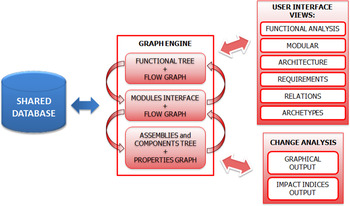
Fig. 4. Implementation of the function-based model into an IT platform.
4.1. The platform architecture
The IT platform architecture able to deploy the proposed approach is shown in Figure 5. It is composed of a knowledge-based engine, using a shared database of different data (i.e., technical, marketing, life cycle, product BOM, product data, and CAD data) and four tools (i.e., a product variants configurator tool, a CM tool, a manufacturing cost estimation tool, and an LCA tool). A database system is filled with the specific parameters obtained from the gathered requirements. Moreover, the values of such parameters are inserted into the database to form a configuration. All the existing product variants can be automatically input capturing the related information from an enterprise resource planning or product life cycle management system. The knowledge-based engine collects also all the compatibility rules that are necessary to validate any set of parameters. In particular, the configurator tool lets marketing and technical users add value to the configuration process. The platform is supposed to be shared between the marketing, design, and purchasing departments offering dedicated graphical user interfaces that provide specific software functionalities.

Fig. 5. The configuration platform architecture.
When a new product variant has to be defined, marketing staff validates the new set of requirements along with design experts in order to define the new functional requirements, solutions, and the relative parameters. Such data represent the starting point for the technical actions. The system interface allows users to define novel product configurations by combining all the wanted parameters. This action is usually carried out by the marketing staff. The interface shows the interested product parameters and adapts them with the addition or removal of records in this table. It also offers the search functionality of existing products to find the product variant closest to the customers’ requirements, based on agent-based models. Four operators are introduced:
-
1. Filter operator: It filters a subset of parameters to find similar configurations. Such an operator is based on parametric queries on the table of requirements.
-
2. Distance operator: It computes the Euclidean distance of two variants expressed in the n-dimensional space of the parameters. Such an operator allows the most similar variants to be found and sorted in an automatic manner.
-
3. Compatibility evaluation: It evaluates the compatibility of a pair of parameters by searching for a variant where the two parameters already coexist. This requires [n · (n – 1)] / 2 pairs to be considered to assess the global validity of a new configuration.
-
4. Rule-based exclusion: It allows logic rules to be input to limit the values that can be assumed by parameters. The syntax is simple and uses not only arithmetic operators but also logic and conditional ones such as and, OR, NOT, EQUALS, and IF.
While the first two operators allow a manual or assisted search to be performed, the last two operators allow a new variant to be automatically assessed. In particular, compatibility evaluation alerts the marketing expert on the novelty introduced by a new combination of parameters. In contrast, the rule-based exclusion operator aims to form a knowledge base that will grow with the everyday usage. Although every rule must be formulated with the help and expertise of the design department, the growth of the rule database progressively will allow the marketing department to be independent. Moreover, the rule set represents a base of explicit configuration knowledge on the specific product family. The user is informed if the new configuration is not consistent (i.e., if parameters are incompatible due to any rules) and an alert is shown. A constraint satisfaction engine is used for rules validation and global product assessment (Ferfernig et al., 2014). Finally, a new configuration is saved in the database increment for the available solutions to be recovered in the future.
The interface shown in Figure 6 provides editing functionality for defining the validity rules, which verify the compatibility of product parameters as new variants are configured. Each rule is composed using a syntax made up of arithmetic, logic, and conditional operators. A dedicated interface facilitates rule definition by listing properties and possible operators. Below, an example of rule is given:
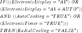 $$\eqalign{& IF (((ElectronicDisplay = ``A1") \;OR \cr &(ElectronicDisplay = ``A1 + AUTO")) \cr &AND \;((AutoCooking = ``TRUE") \ OR \cr &(ElectronicTimer = ``TRUE"))) \cr & THEN (RadialCooling = ``FALSE")}$$
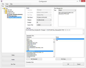
Fig. 6. The configuration tool interface for checking input validity rules.
Such an interface also provides messages associated to the rule in order to provide clues and explanations to the user about the new configuration based on a recommender system approach (Ferfernig et al., 2013). The rules, and hence the message associated with them, are classified according to their severity:
-
• Information rule: The message reports an advice or useful information.
-
• Exclamation rule: The message warns the marketing user that something is to be added, changed, or removed in the current configuration but is not crucial.
-
• Critical rule: The message alerts that the current configuration is not feasible and recommends which values of the parameters have to be changed or which parameters have to be added or removed.
In addition, a tooltip is associated with each parameter, providing specific information. Finally, the rule can be enabled or not and then saved. Not all cases are covered by these rules, namely, the combination of parameters of the new variant configurations created by the marketing user could not be related to rules or simply there are no contraindications to the configuration. Therefore, similar past configurations can be searched, but if the parameters that represent the change are not present in the company history, this is the case to send a preliminary evaluation to the technical department.
The CM tool comes to the aid of the design department when the assessment of a new variant is required. The designer uses the model representation to estimate the change propagation and its impact on the product structure from the properties of one or more blocks to be changed (Fig. 7).
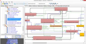
Fig. 7. The change management tool interface for variant management.
The graph engine collects and computes the three representation levels (functional structure, modular structure, and product architecture) and the related graphs. The software provides a graphical user interface for managing the three representation domains. The requirements view lets the user set the impact indices for the properties to all identified design contexts, which, as stated above, are seen as a classification of the product requirements. The relations view allows inputting standard relations between properties of the blocks. The archetypes tab is the overview about all the components involved in all the considered product families. Then, the graphical output related to the change propagation and the values of the output of the change impact indices are part of the software module of change analysis.
Finally, the CM tool has the possibility to communicate other company repositories, such as an LCA tool and a cost estimation module that allows the technical users to have a more accurate evaluation of the impact indices. Such indices are required by the CM tool for the computation of the change impacts regarding the design contexts related to life cycle analysis and costs. LCA is a well-known methodology that allows evaluating environmental impacts related to a product, both manufactured or consumed, process or activity. It examines the entire life cycle, from cradle to grave, and the potential environmental impact intended, for example, as the use and consumption of natural resources (i.e., extraction, treatment, and processing of raw materials) and the environmental consequences of dross due to production and transport, its use and reuse and maintenance until the recycling and its final disposal. It is accomplished through the identification and quantification of the raw materials and energy consumption and emissions. It allows comparing quantitatively similar products and identifying and evaluating opportunities to reduce the impacts. It can be performed at any stage of the life cycle, but its usefulness is predominant in the initial stage of design. The reference standards that describe in detail the requirements for conducting an LCA are ISO 14040 and ISO 14044. As far as the LCA tool, the platform includes commercial software, for example, SimaPro (https://www.pre-sustainability.com/simapro). It provides collecting, analyzing, and monitoring the sustainability performance of products and service in an easy way by modeling and analyzing complex product life cycles in a systematic and transparent way, measuring the environmental impact of products and services across all life cycle stages thanks to structured databases containing a wide range of inventory data and impact assessment methods (it also includes the Ecoinvent database), and identifying the hotspots in all aspects of the supply chain, from extraction of raw materials to manufacturing, distribution, use, and disposal. Such analyses are executed on single parts or an entire product family, or part of them. In the case of family, it allows understanding if the introduced change leads to a variant that improves or not its environmental impacts. The designer can evaluate if the introduced modification is convenient or not and assess the impact index value used in the CM tool. If the environmental impact computed with the LCA tool differs from the impact index value, a tuning can be executed.
Cost is another of the main design drivers considered by the platform. Its evaluation in the early design phases allows cost-effective choices to be performed. The platform includes the commercial software LeanCOST (http://www.hyperlean.eu/?page_id=1168&lang=en), which is based on an analytical approach for the cost estimation issue (Fig. 8).

Fig. 8. Cost estimation tool architecture (adapted from Mandolini et al., 2012).
LeanCOST estimates times and costs of manufacturing cycles from a knowledge-based approach. Its interface is shown in Figure 9. The system interacts with the above-mentioned function-based product representation to retrieve geometric and nongeometric information (e.g., material, tolerances, and surface treatments) in order to apply its cost models.
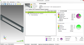
Fig. 9. The cost estimation tool interface.
In particular, cost is estimated considering four components:
-
1. machining cost: the time in which the machine works the piece multiplied by the machine unitary cost;
-
2. stock cost: the stock weight required to manufacture the final product multiplied by the stock unitary cost;
-
3. accessory cost: the time in which the machine does not work the piece (i.e., machine is changing tool or piece) multiplied by the machine unitary cost; and
-
4. machine setup cost: the time during which the machine is performing activities at the beginning of a batch production (e.g., computer numerical control program testing and tool setting up) multiplied by the machine unitary cost.
The first three costs are specific for a single component, but the fourth depends on the production batch dimensions.
With similar intents of use than the LCA tool, the inclusion of this software in the platform allows understanding the impact of the change from the costs point of view. The feedback allows tuning the CM tool for more accurate change impact estimations. Cost estimation and LCA analysis have been considered and involved in the platform before other computer-aided engineering tools because of the importance of such analysis from the preliminary evaluations of a variant. In any event, the redesign platform architecture is able to integrate other kind of tools based on a similar interaction approach.
4.2. The industrial case study: Product configuration for household appliances
The proposed approach as well as the defined platform were validated on industrial case studies in collaboration with Electrolux, a global leader in home appliances and appliances for professional use. In particular, the hot division was involved and the case study product variety consisted of three kinds of products: the freestanding (FS) cooker, the built in (B-I) hob, and the B-I oven (Fig. 10).
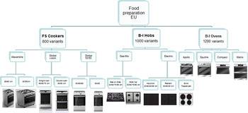
Fig. 10. Electrolux hot division product families.
There are about 3000 variants of these types of product, and they are upgraded and enhanced continuously. Dimensions, frame shape, number of burner and its type (induction or gas), and colors are only a few examples of properties that a marketing specialist could combine to generate a new product variant. In this context, a FS cooker was chosen as a representative product as it combines the structures of an oven and a hob, two main product types that identify the hot division.
The starting point for the functional analysis of any product was to find a function, the “black box,” that gathers the basic function of the product. For a FS cooker, this base function is “cook food” (Fig. 11).

Fig. 11. The “black box” function for a cooker product.
Input and output flows from the black box were identified and cascaded into the product sublevels. Inputs for the base function are food, energy, and signal (e.g., inputs given by a user). The external contamination represents the dust belonging to the external environment. As output, in addition to energy, signal, and cooked food, the dross represents both the waste derived from cooked food and the dust removed, for example, from the surfaces. In the first level of the functional decomposition (Fig. 12), three key functions have been identified, recalling the three main targets of the product: safety (not only for the user but also for the product), cooking, and cleaning. Table 2 shows the whole identified functional decomposition, which moves from the three main subfunctions and reaches the third level depth. The modular product structure was derived from the third level of the functional decomposition. Stone's (Reference Stone, Wood and Crawford2000) three heuristics (i.e., the dominant flow, the branching flow, and the conversion-transmission flow) and the MFD method were used to identify the modules, which have been reported in the last column of Table 2.
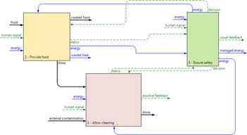
Fig. 12. First level of the functional modeling decomposition.
Table 2. Functional decomposition of the analyzed freestanding oven

In order to define the product architecture, the BOM of a real product has been analyzed. In particular, the freestanding cooker (model ZCG6600MW, Zanussi) has been chosen (Fig. 13). Its analysis provided the recognition of the subfunctions implemented by each component of the product BOM, and the identification of the most significant components out of the BOM, which were linked to the implemented functions. Down line of this analysis, the functional auxiliary relations will be automatically stored in the structure. Each component carried out more subfunctions as reported in Table 3, where the strikethrough components were considered not significant for the analysis.
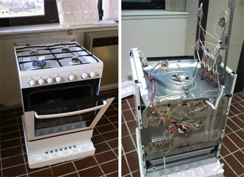
Fig. 13. The analyzed freestanding cooker.
Table 3. Portion of the components mapping of the FS cooker articles to the functional analysis

The industrial case study focused on a marketing specialist who wants to configure a new B-I oven variant. The first step is searching for existing configurations using the marketing interface of the configurator tool (Fig. 14). After that, the specialist may want to investigate in the parameters group “appearance” if there are variants with the “details” and a specific kind of knob [i.e., Pop In Pop Out (PIPO) color black]. The search provides only one result: model code E949714418 (Fig. 15). If the specialist wants to know if any similar configurations exists according to specific changes, the search engine finds two similar configurations as shown in Figure 16 (i.e., the configuration with a standard gray knob and the configuration with a “full glass” control panel). Therefore, starting from the initial configuration found (code E949714418), the specialist creates a new variant and can evaluate the effect of the introduced changes and its feasibility (Fig. 17).
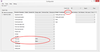
Fig. 14. Configurator tool in use for existing configuration search.
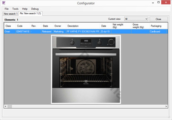
Fig. 15. Example of search results.

Fig. 16. Search results: similar configurations analysis.
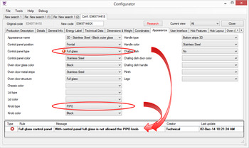
Fig. 17. Change not feasible due to incompatible parameters.
Subsequently, due to parameters incompatibility highlighted by the configuration tool, the designer investigates the effect of the introduced change by a control panel by the CM tool. As stated above, the product architecture in this case focuses on a general B-I oven configuration. The functional representation and the existing connection between components and functions allow the automatic instantiation of auxiliary functional relations. Figure 18 shows the product architecture and structure of the entire product (i.e., the oven). By selecting the right component variant from the code property, it is possible to represent the starting configuration to which to apply the desired change. Now, the impact of such change can be easily visualized on the control panel. The impact is evaluated to understand the related benefits as shown in Figure 19. The probability of components change can be estimated thanks to the functions’ parameters analysis, and represented by graphs as shown in Figure 20.

Fig. 18. Representation in the change management tool of the product architecture of the analyzed oven.
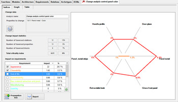
Fig. 19. Investigation on the change impacts.
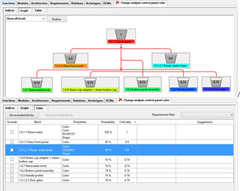
Fig. 20. Analysis of the probability of components change.
Finally, thanks to the connection with the LCA and the cost estimation tools, the environmental and the economical impacts of the new variant are analytically computed. The platform uses the standard system interfaces (i.e., SimaPro and LeanCOST), but data about the product characteristics (e.g., dimensions, materials, and finishing properties) are directly taken from the configuration tool to have a complete assessment of the new product variant, supporting decision making at both technical and strategic levels.
5. CONCLUSIONS
Functional modeling and modularity introduce advantages in product design and definition of product platforms in order to meet the customer needs without suffering the disadvantages of excessive variety of parts. However, when complex products have to be reconfigured into a modular architecture to have practical engineering applications and support product industrialization, understanding the best approach to be used for the required functional representation is not a trivial task. This paper introduced a multilevel product representation grounded on functional analysis and defined a software platform in order to face the redesign process of product variants into product families. The redesign platform lets marketing specialists configure new variants by the search of past solutions and configuration rules that suggest feasible combinations or prevent unfeasible ones, and avoid iterations between marketing and technical departments. Rules are input in the system from technical experts of the company, capturing their knowledge. As all configurations cannot be evaluated from past cases, a CM tool is introduced to let designers understand in the early phase the impacts that this new solution can bring.
The capability of the proposed platform to deal with the redesign process of product variants across several stakeholders into the company is achieved by the multilevel representation of the same product, which allows capturing the key aspects of the entire product family from the early design phases. Traditional function diagraming demonstrated its usefulness in capturing the main product functionalities and highlighting the main flows of signal, energy, or material among subfunctions. Then, the modular structure, derived from the functional decomposition, allows focusing on the most convenient subdivision in poorly interconnected and replaceable units.
However, two such representation levels, being tight to an abstract view on the system, are not fully able to highlight the propagation of modifications into the product structure as necessary in design review activity. Therefore, a third highly interconnected representation of the product structure is introduced to compensate the functional view, containing part instances and properties with determined values.
Although a complete integration between the several platform systems is still missing, this work tends to contribute to the creation of a computer-aided redesign environment starting from the requirements acquisition until the cost estimation phase, by creating a seamless workflow supported by adequate software tools and procedures. It demonstrates the necessity of functional representations to be completed by additional views about the physical product structure in order to support feasibility study and engineering decision making.
Finally, the functional and modular structure of the freestanding oven is reported in details in order to foster research benchmarking with other modeling approaches. The oven denotes a nontrivial test case, which is useful in cross-comparison of algorithms and methods on midsized structures.
Margherita Peruzzini is an Assistant Professor in the Department of Engineering Enzo Ferrari at the University of Modena and Reggio Emilia and coordinates the Virtual Prototyping Lab (ViP Lab) of Modena Technopole. She obtained her Master's degree in industrial mechanical engineering and her PhD in mechanical engineering and engineering management. Margherita is participating in several research projects at the national and European level and in other scientific communities. She is the author of more than 80 international publications in international journals and conference proceedings. Dr. Peruzzini's research topics are design for X, integrated product–process design, virtual prototyping, and digital manufacturing.
Roberto Raffaeli is an Associate Professor at eCampus University, Italy. He graduated with a degree in mechanical engineering at the University of Ancona and earned a PhD in research in mechanical engineering. Roberto is the author of over 70 international scientific publications, of which about 20 are in international journals. Dr. Raffaeli's research mainly focuses on modularity, parameterization, reverse engineering, geometric modeling, computer graphics, and mechanical aid systems, as well as in related fields such as medical and footwear, through the development of software mainly dedicated to CAD–computer-aided engineering.
Marco Malatesta is a PhD Fellow in mechanical design. He also works as a Senior Analyst and Software Developer in a company developing CAD-based tools for cost engineering and configuration design (Hyperlean Srl).. He attained his PhD at the Polytechnic University of Marche. Hyperlean was born as a spin-off of the Polytechnic University of Marche in 2010.
Michele Germani is a Professor in mechanical design and life cycle product design in the Department of Industrial Engineering and Mathematical Sciences at the Polytechnic University of Marche. He received his PhD in mechanical measures at the University of Padua. He is a member of the Scientific and Technical Committee of the Interdepartmental Centre on Innovation and Entrepreneurship. Dr. Germani is the author of more of 150 international publications in journals and conference proceedings.


