


NOMENCLATURE
- AI/DI
-
anti-icing/de-icing
- CF
-
carbon fibre
- CFRP
-
carbon fibre reinforced polymer
- CNT
-
carbon nanotube
- CVD
-
chemical vapour deposition
- GF
-
glass fibre
- GFRP
-
glass fibre reinforced polymer
- ILFT
-
interlaminar fracture toughness
- IR
-
infrared
- LSP
-
lightning strike protection
- R
-
resistance
- SEM
-
scanning electron microscope
- SHM
-
structural health monitoring
- UD
-
unidirectional
- $\Delta$
R
$\Delta$
R
-
change in resistance

1.0 INTRODUCTION
Owing to its superior specific strength and stiffness, carbon fibre reinforced polymer (CFRP) composites are increasingly being used in diverse sectors, such as marine, automotive, sports and, in particular, aerospace, where they comprise around half the weight of the primary structure of the latest generation wide-body passenger aircraft such as the Boeing 787 and A350 XWB(Reference Mcconnell1). This revolution in materials and fabrication, together with ever increasing pressure to reduce fuel consumption has provided the impetus for the development of multifunctional structures incorporating such functionality as structural health monitoring (SHM)(Reference Diamanti and Soutis2-Reference Gao, Chou, Thostenson, Zhang and Coulaud5), lightning strike protection (LSP)(Reference Zhang, Soltani, Le and Asmatulu6-Reference Guo, Xu, Wang, Dong, Yi and Jia10) and improved ice protection systems(Reference Yao, Falzon, Hawkins and Tsantzalis11-Reference Zhao, Chen, Liu, Liu and Zhang18) whilst also delivering enhanced structural performance such as higher interlaminar fracture toughness (ILFT)(Reference Nistal, Falzon, Hawkins, Chitwan, Garcia and Rubio19-Reference Ou, Gonzalez and Vilatela23).
Directly drawable carbon nanotube web (CNT web) is a uniquely adaptable and useful material composed of highly aligned, small multiwalled CNTs. It is electrically conductive, particularly in the draw direction, extremely light and flexible, and highly compatible with composite materials. We have reported previously on the use of CNT web to address SHM(Reference Kumar, Falzon and Hawkins4) and ILFT(Reference Nistal, Falzon, Hawkins, Chitwan, Garcia and Rubio19,Reference Leonardo, Nistal, Catalanotti, Hawkins and Falzon20) . We also described the creation of a CNT web-based electrothermal element as part of an AI/DI system for aerospace applications(Reference Yao, Falzon, Hawkins and Tsantzalis11-Reference Yao, Falzon and Hawkins13). Such an AI/DI element would be located on critical aircraft wing and nacelle lip leading edges, which are also the areas most susceptible to impact. Hence, the AI/DI elements would be the first to suffer impact damage (which may leave no visible mark), necessitating a mechanism to detect damaged areas and to repair them, and this is now reported. The laminate structure of CFRP composite also makes it susceptible to impact damage(Reference Donadon, Iannucci, Falzon, Hodgkinson and Almeida24-Reference Faggiani and Falzon27). The mechanism for detection of damage to the AI/DI element also facilitates the localisation of potential damage to the underlying CFRP composite, further enhancing the multifunctional value of CNT web. The flexibility of the CNT web-based electrothermal system was demonstrated by applying it to the leading-edge surface of a representative composite wing section provided by Spirit Aerosystems Belfast.
2.0 EXPERIMENTAL SECTION
2.1 Materials and sample preparation
Woven glass fibre (GF)/epoxy prepreg (RE295/SE84LV) and dry woven glass fabric (RE50P), with areal weights of 292 gsm and 47 gsm, respectively, were supplied by Gurit (UK) Ltd. Unidirectional spread tow carbon fibre (UTS50S) thin ply, with an areal weight of 32 gsm(Reference Russello, Diamanti, Catalanotti, Ohlsson, Hawkins and Falzon28), was supplied by TeXtreme (Sweden). IN2 epoxy resin and copper foil (0.025 mm thick, annealed, uncoated, 99.8%) were purchased from Easy Composites (UK) and Alfa Aesar (UK), respectively. Highly aligned forests of long, thin, few-wall CNTs were fabricated in-house by chemical vapour deposition (CVD) (Fig. 1a), grown on a silicon wafer with an iron catalyst, yielding an average CNT length of 300 μm (Fig. 1d,e), an average CNT diameter of 10 nm(Reference Atkinson, Hawkins, Huynh, Skourtis, Dai and Zhang29,Reference Huynh and Hawkins30) and an average wall number of around 7. CNT web was directly drawn from the CNT forests (Fig. 1b-e). The CNT web is highly aligned and anisotropic (orthotropic)(Reference Zhao, Chen, Liu, Liu and Zhang18) with an electrical resistance in the draw direction [0°] only $\sim$
4% of that in the transverse direction [90°] (Fig. 1).
$\sim$
4% of that in the transverse direction [90°] (Fig. 1).
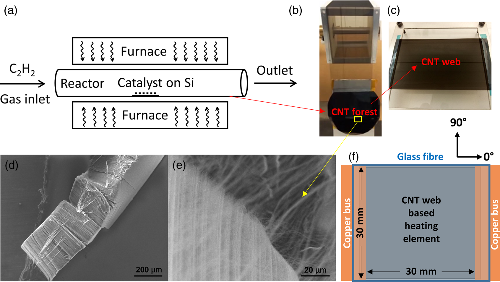
Figure 1. (a) Schematic of CVD. (b) Directly drawn CNT web from CNT forest. (c) CNT web on a mounting frame. SEM images of (d) CNT forest and (e) its drawing. (f) Sample specifications.
Samples, with the number of CNT web layers and their alignment, were arranged in five different layups. Four samples comprised CNT web alone: [0]10, [0]20/[90]20, [45]20/[–45]20 and [0]5/[45]5/[–45]5/[90]5, are denoted A to D. The fifth sample comprised a single layer of unidirectional (UD) thin ply carbon fibre in addition to 20 0° CNT layers, [0]20/[90*] and is denoted E. The thickness of 10 layers of CNT web in resin is $\sim$
6 µm, resulting in an overall laminate thickness of 0.60 mm, 0.62 mm, 0.62 mm, 0.61 mm and 0.63 mm for sample A to E. The square heating element comprising the CNT (or CNT/UD thin ply) web stack was sandwiched between two layers of glass fibre reinforced polymer (GFRP) to electrically isolate it from a putative CFRP structure, and with copper foil buses at two opposite sides in the 90° direction with a final sample size of 30 mm
$\sim$
6 µm, resulting in an overall laminate thickness of 0.60 mm, 0.62 mm, 0.62 mm, 0.61 mm and 0.63 mm for sample A to E. The square heating element comprising the CNT (or CNT/UD thin ply) web stack was sandwiched between two layers of glass fibre reinforced polymer (GFRP) to electrically isolate it from a putative CFRP structure, and with copper foil buses at two opposite sides in the 90° direction with a final sample size of 30 mm $ \times $
30 mm (Fig. 1f). The assembly was prepared using the vacuum bagging technique and cured according to manufacturer (Gurit) specifications for SE84LV.
$ \times $
30 mm (Fig. 1f). The assembly was prepared using the vacuum bagging technique and cured according to manufacturer (Gurit) specifications for SE84LV.
2.2 Impact damage and repair methods
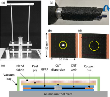
In order to see the effect of impact damage on, and the repairability of, the CNT web/GFRP electro-thermal system, an in-house constructed dropweight device based on the ASTM D7136 standard, with a 1.266 kg (Fig. 2a), 10 mm diameter hemispherical impactor, and impact energy of 3 J was used. The electrical resistance and thermal performance were measured before and after impact, and damaged samples inspected by SEM. The repair procedure (Fig. 2b-d) entailed preparation of a 1wt% dispersion of the CNT forest in IN2 epoxy resin (resin and slow hardener mixed in the ratio of 100:30) through light roll milling for approximately 1 minute (Fig. 2c) using an in-house built miniature mill. The CNT forests grown by this CVD method are not only able to be drawn into webs, but also very easy to disperse uniformly in epoxy when processed properly. The highly viscous CNT/epoxy mixture was painted onto the impact damaged areas of each sample, which was then placed on an aluminium tool plate. A layer of peel ply and two layers of bleed fabric were applied to the top, and the cure procedure applied according to manufacturer (Easy Composites) specifications for IN2 through vacuum bagging (Fig. 2e).
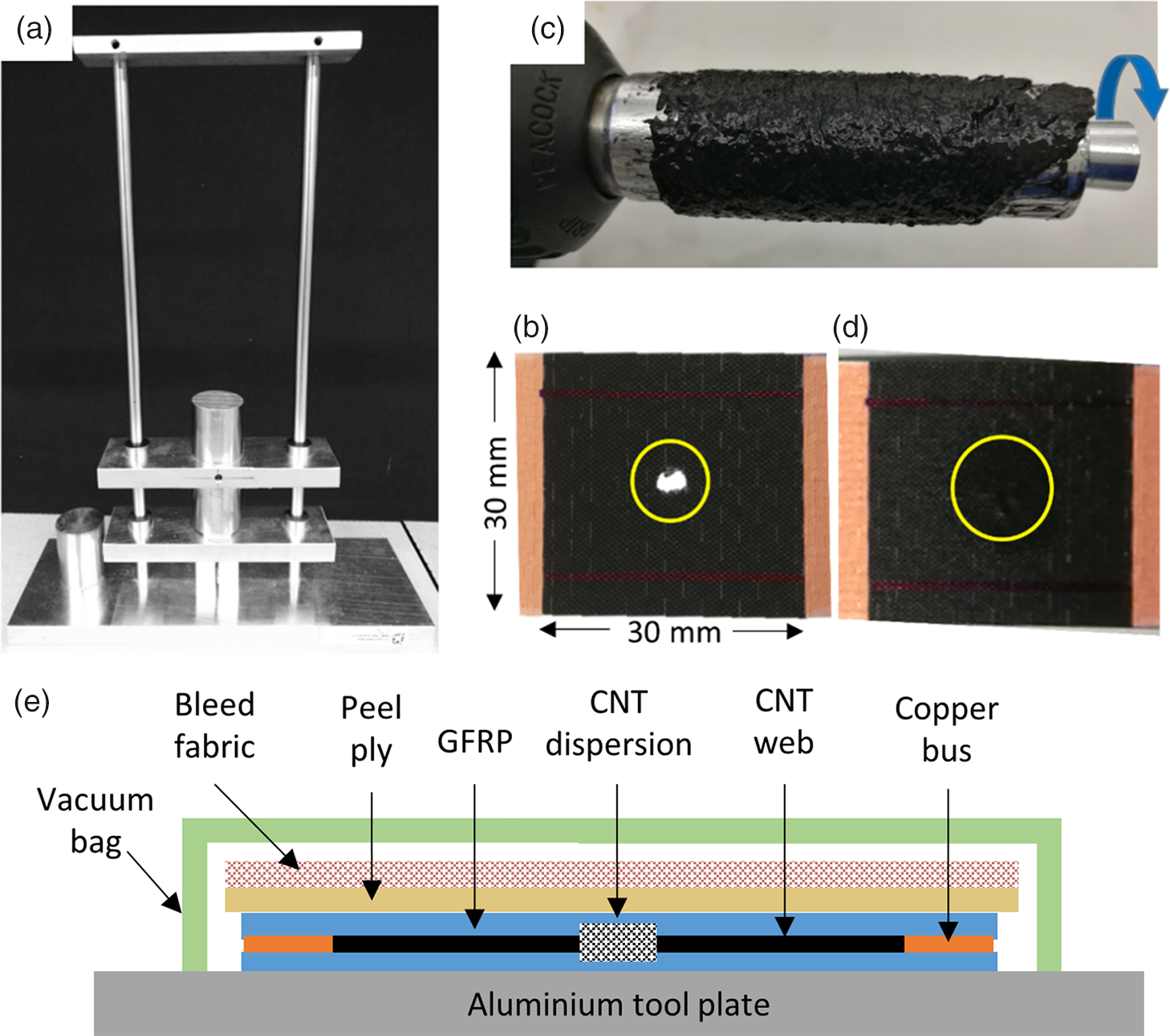
Figure 2. (a) In-house constructed impactors. (b) Sample D after impact. (c) CNTs dispersed in epoxy through roll milling. (d) Dispersed CNT applied to the damaged sample D for repair. (e) Repair through vacuum bagging.
2.3 Characterization
The resistive heating performance of the composites was investigated, with the voltage and current controlled by an EA Elektro-Automatik PS 3016-20B Digital Bench Power Supply operated at 10 – 12 V (maximum voltage/current: 16 V/20 A). The temperature distribution was monitored by a FLIR SC640 thermal imaging camera (640 × 480 pixels superior resolution, thermal sensitivity of 30 mK, 2°C accuracy), with the samples held horizontally in a still air environment. An Agilent 34450A 5½ Digit Multimeter was employed to measure the resistance of the samples using the 4-wire method. The morphology of CNTs was characterised by a Hitachi FlexSEM1000 Scanning Electron Microscope (SEM).
3.0 RESULTS AND DISCUSSION
3.1 Impact and repair performance of the CNT web-based electro-thermal system
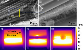
Our previous work(Reference Yao, Falzon, Hawkins and Tsantzalis11-Reference Yao, Falzon and Hawkins13) demonstrated the fabrication and performance of CNT web-based electrothermal elements for application in aerospace composites, and how the orthotropic character of the highly aligned CNT web could be designed according to specific requirements(Reference Yao, Falzon and Hawkins13). As such systems would be placed on areas susceptible to impact damage, it was evident that a method to detect and repair such damage would be required and is reported here. The methodology depends on the phenomenon of sword-in-sheath breakage commonly observed with small multiwalled CNTs(Reference Yu, Lourie, Dyer, Moloni, Kelly and Ruoff31) where the outer wall in contact with the matrix fractures while the inner CNT structure partially pulls out before breaking. This creates a fringe of clean CNTs (Fig. 3a,b) along the fracture line that can readily be reconnected. Use of a concentrated dispersion of the same CNT material ensures maximum conformability and connectivity across the break. Whereas the pristine heater uses highly aligned CNT web to capture the efficiency and flexibility of this material, the repair necessarily uses dispersed or disordered CNT, which is adequate for limited distance conduction that does not degrade the overall heater characteristics. Thus, it should be noted that if a larger damaged region is removed in preparation of a scarf repair, the scale of the CNTs is such that nanoscale CNT protrusions would still be present around the edges. Under such circumstances it is anticipated that a plug patch prefabricated with aligned CNT web could be used with the edges being reconnected using the CNT dispersion.

Figure 3. (a) SEM image of fracture edge of Sample A [0]10 after impact showing (b) projecting CNT filaments. Thermal performance (c) before and (d) after impact and (e) after repair.
3.1.1 Unidirectional layup
A simple unidirectional CNT web layup with few web layers (Sample A, [0]10), which is most susceptible to inhomogeneities in the web assembly(Reference Yao, Falzon and Hawkins13), was used to indicate the maximum effect of impact damage (Fig. 3c-e). As the CNT web has low transverse conductivity, heating in the undamaged specimen is slightly uneven (Fig. 3c). However, the impact punched a nearly circular hole through the sample and created an open circuit cold zone across the entire element (Fig. 3d) while the resistance increased by 17.8% (Table 1), which accords with the ratio of the dark (cold) to bright (heated) areas. In addition to being able to draw CNT forests into webs, the CVD CNTs are also very easy to disperse if processed appropriately. After the repair (Fig. 3e), the resistance returned to the value before the impact (Table 1), suggesting that the dispersed CNTs are primarily reconnecting the broken CNT ends protruding from fractures (Fig. 3a,b) rather than forming a bypass or auxiliary heater in their own right.
Table 1 Resistance before and after the impact (3 J) for heaters with different layups
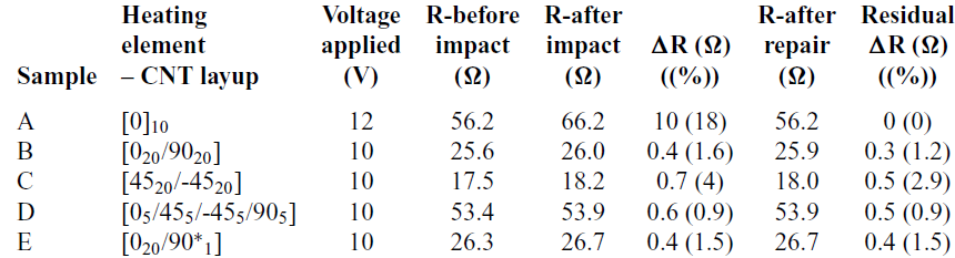
* Note: All the heating elements are made only of CNT web except for sample E where [90*]1 represents 1 layer of CF thin ply, plus 2 layers of GFRP.
Once repaired and cured, the broken heating path was almost fully recovered with only a relatively small drop in temperature at and around the impact site of the sample (Fig. 3e). This indicates that the heating characteristic of the mass of dispersed CNTs is not quite as good as that of the CNT web. This may be improved by optimization of the CNT loading or resin cure. A better though slower approach to repairing a sizeable hole might be to prepare a CNT web/GFRP patch and join the edges with dispersed CNT in resin. Of particular note is that the heating element can also be used as a sensor by both electrical resistance measurement and especially by infrared (IR) imaging, as it shows the location of damage to the heater structure and, by inference, potential damage to the underlying composite.
3.1.2 Cross-ply layups
As a heater with unidirectional CNT web loses a significant area of operation when damaged due to the open circuit and resulting linear unheated area (Fig. 3), it was of importance to determine if a different layup structure could make the heater more resilient to damage (i.e. continue functioning effectively), whilst also providing a better indication of the location and severity of damage. Elements comprising more layers of CNT web and with different layup pattern were prepared (Samples B, C, D). In addition, a CNT heater comprising 20 layers of unidirectional CNT web (0°) plus 1 orthogonal unidirectional thin ply CF layer (i.e. at 90o to the applied electric field) was prepared (Sample E, Table 1). The thin CF ply is approximately 15 µm thick and contributes little to the conductivity or heating function as demonstrated by the resistance, which is very close to that for Sample B ([020/9020]); however, it was anticipated from previous work(Reference Yao, Hawkins and Falzon12) to provide a useful bridging function for minimal additional weight.
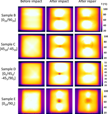
The use of cross-ply layers of CNT (or one CF thin ply) greatly improves the uniformity of heating (Fig. 4) in the CNT web element(Reference Zhao, Chen, Liu, Liu and Zhang18). Moreover, it dramatically enhances heater resilience, to impact, with the point of impact showing up as a cold spot with only minor to minimal cooling in the zones to either side (Fig. 4) towards the distribution buses. The change in resistance following impact decreased from 10 Ω, or nearly 18% (Sample A) to less than 1 Ω or 4% when cross-ply layups were used (Table 1). After repair there is a small residual increase in resistance of up to 0.5 Ω (2.9%), which possibly reflects the resistance of the CNT dispersion or incomplete reconnection of the broken CNT fringes. Optimisation of the CNT loading and dispersion, and application process are expected to further reduce this disparity.
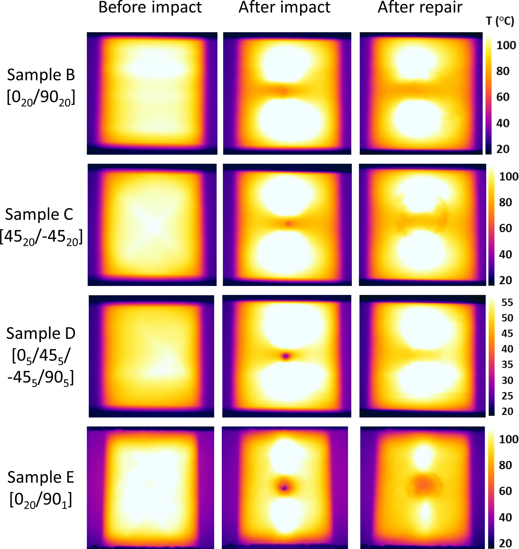
Figure 4. Heating performance of cross-ply samples with different layup before impact, after impact and after repair.
The linear unheated area seen in the unidirectional sample is almost eliminated by the use of a cross-ply layup such as sample D, which has a quasi-isotropic layup, being marginally more uniform than the other patterns. The actual damage locus is very evident in the cross-ply samples and readily repairable by the method described, with sample D again showing the best uniformity after repair.
3.2 Flexibility of the CNT web-based electro-thermal system
In addition to its repairability and sensing function, the flexibility of the CNT web-based electro-thermal system was investigated with the CNT web layers ([0]15) embedded between two layers of dry woven glass fabric (RE50P). The CNT/GFRP assembly was fabricated by vacuum-assisted resin infusion using IN2 resin. After curing (Fig. 5a), the device was cut into the shape of a model wing leading edge section (Fig. 5b) and applied to its surface (Fig. 5c). The device was fabricated with unidirectional (0°) CNT web, so the orthogonally oriented anisotropy of this structure results in the resistance increasing from 178 Ω to 462 Ω when cut from a rectangular (Fig. 5a) to a chevron shape (Fig. 5b) to conform to the leading edge profile. At the maximum voltage (16 V) applied, the IR image (Fig. 5d) shows the highly conformal device as well as the effect of using the unidirectional CNT web, with the warmest zone corresponding to the most direct conduction path, as discussed in an earlier paper(Reference Yao, Falzon and Hawkins13).
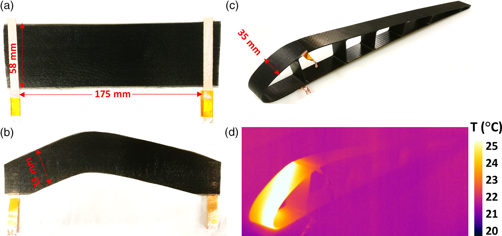
Figure 5. CNT web/glass fabric composite heater (a) original sample, (b) after being cut into a conformal shape, then (c) applied onto the aircraft wing section and (d) heating performance viewed by IR camera.
4.0 CONCLUSIONS
Directly drawn CNT web has been demonstrated to produce a flexible, efficient, lightweight electro-thermal heating system. The CNT web is highly anisotropic with current flow primarily in the draw direction, so the layup pattern has a significant effect on the heating efficiency, thermal distribution and impact tolerance of the heater but also allowing for the design of layup patterns to achieve a predictable heat distribution. The unidirectional layup, where there is very little transverse conductivity and hence pathway for current in the event of a breakage, after impact, exhibited near-complete open circuit and heating failure in line with the damage. However, a method was developed so that this could be easily and quickly repaired with dispersed CNTs. Furthermore, through designing the layup, the heating element can be made much more resilient to damage with minimal change in resistance and performance as a result of impact damage whilst retaining the capacity to exhibit damage by IR photography. Repair is equally simple for such damage. In addition, the flexibility of the CNT web-based electro-thermal system was demonstrated through fabricating a CNT/GF/epoxy composite and applying to the surface of the leading edge of a representative composite wing section.
Acknowledgements
The authors would like to acknowledge the financial support received from the European Union’s 7th Framework Programme for Research under the Marie Curie Career Integration grant agreement No. 630756. We also acknowledge EP/N007190/1, the UK Engineering and Physical Sciences Research Council (EPRSC) grant.


 Open access